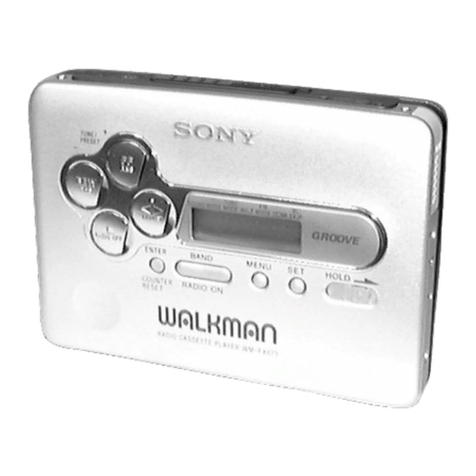
Sony Walkman WM-FX161 User manual

MICROFILM
SERVICE MANUAL
RADIO CASSETTE PLAYER
Canadian Model
E Model
Model Name Using Similar Mechanism WM-FX101
Tape Transport Mechanism Type MF-WMFX103Y-48
SPECIFICATIONS
WM-FX161
87.6 – 108 MHz (Canadian)
87.6 – 107.9 MHz (E)
AM: 530 – 1,710 kHz (Canadian)
531 – 1,602 kHz (E)

– 2 –
TABLE OF CONTENTS
1. GENERAL ................................................................... 3
2. DISASSEMBLY ......................................................... 4
3. DIAL POINTER SETTING .................................. 6
4. MECHANICAL ADJUSTMENTS....................... 7
5. ELECTRICAL ADJUSTMENTS......................... 7
6. DIAGRAMS
6-1. Block Diagram ................................................................ 9
6-2. Printed Wiring Board ...................................................... 11
6-3. Schematic Diagram ......................................................... 13
7. EXPLODED VIEWS................................................ 16
8. ELECTRICAL PARTS LIST ............................... 18 Flexible Circuit Board Repairing
• Keep the temperature of the soldering iron around 270 ˚C dur-
ing repairing.
• Do not touch the soldering iron on the same conductor of the
circuit board (within 3 times).
• Be careful not to apply force on the conductor when soldering
or unsoldering.
Notes on chip component replacement
• Never reuse a disconnected chip component.
• Notice that the minus side of a tantalum capacitor may be dam-
aged by heat.
SERVICING NOTES
HOWTO CHANGETHE CERAMIC FILTERS
This model is used two ceramic filters of CF2 and X2.
You must used same type of color marked ceramic filters in order
to meet same specifications.
Therefore, the ceramic filter must changed two pieces together
since it's supply two pieces in one package as a spare parts.
Mark Center frequency
red 10.70MHz
blue 10.67MHz
orange 10.73MHz
black 10.64MHz
white 10.76MHz
mark CF2
X2

– 3 –
SECTION 1
GENERAL This section is extracted from
instruction manual.

– 4 –
CABINET (REAR) ASS’Y
1
Insert the precision screw driver
(1.4 mm flat-blade) in to the slit
at claw
A
and release the claw.
2
Remove the cabinet (rear) ass’y. (Re-
lease all claw
B
to
M
in alphabetical
order.)
MECHANISM DECK (MF-WMFX103Y-48)
AND MAIN BOARD
Note: Follow the disassembly procedure in the numerical order given.
SECTION 2
DISASSEMBLY
• This set can be disassembled in the order shown below.
cassette holder
A
cabinet (rear) ass’y
BC
D
E
I
K
M
L
J
H
G
F
1
Remove the mechanism deck
(MF-WMFX103Y-48) and MAIN board
in the direction of the arrow.
Note: Make sure to put the head
flexible board to ditch befor
e
install the mechanism deck
and MAIN board.
SET CABINET (REAR) ASS’Y MECHANISM DECK (MF-WMFX103Y-48)
AND MAIN BOARD MAIN BOARD
CASSETTE HOLDE
R

– 5 –
MAIN BOARD
CASSETTE HOLDER
3
three claws
4
MAIN boar
d
1
head flexible board
(CN301)
2
Remove the solder
of the motor wire.
front cabine
t
3
cassette hoder
1
Insert a precision screwdriver
(1.4 mm flat-blade) vertically
in to portion
A
to release
the hinge plate.
2
Portion
B
to release
the hinge plate.
A
B

– 6 –
Note: Follow the assembly procedure in the numerical order given.
SECTION 3
DIAL POINTER SETTING
align
pointe
r
Fig. 1
1
Rotate tune knob fully to arrow direction.
2
Align pointer with arrow
marked side as shown in
Fig. 1 and then fit to groove
in the order of
A
and
B
.
pointer
B
A

– 7 –
SECTION 4
MECHANICAL ADJUSTMENTS
Mode Tension Meter Meter Reading
FWD CQ-403A more than 40 g
(more than 1.4oz)
•Tape Pulling Force Measurement:
PRECAUTION
1. Clean the following parts with a denatured-alcohol-moistened
swab:
playback head pinch roller
capstan rubber belt
2. Demagnetize the playback head with a head demagnetizer.
3. Do not use a magnetized screwdriver for the adjustments.
4. The adjustments should be performed with the rated power
supply voltage (2.5V) unless otherwise noted.
•Torque Measurement:
Mode Torque Meter Meter Reading
FWD 20 – 42 g•cm
(0.28 – 0.58 oz•inch)
FWD CQ-102C less than 2 g•cm
Back Tension (less than 0.03 oz•inch)
FF, REW CQ-201B more than 60 g•cm
(more than 0.83 oz•inch)
SECTION 5
ELECTRICAL ADJUSTMENTS
PRECAUTION
• Supplied voltage : 2.5 V
• Switch and control position
VOL control : maximum
AVLS switch : NORM
NORM•DX CrO2/METAL•LOCAL switch :
NORM•DX (Canadian)
NORM•ST CrO2/METAL•MONO switch : NORM•ST (E)
TAPE SECTION
Setup :
FM AM TAPE switch : TAPE
Test Tape
1. Play back WS-48A (tape center part) and Adjust the RV601 so
that the frequency counter reading becomes 3,000 Hz ± 15 Hz
2. Play back WS-48A tape the beginning and the end part.
Check that the frequency counter reading is within 1.5 % of
the reading of step 1.
Tape Signal Used for
WS-48A 3 kHz, 0 dB Tape Speed Adjustment
0 dB = 0.775 V
Tape speed adjustment
Procedure :
+
–
test tape
WS-48A
(3 kHz, 0dB) frequency
counter
set
2
jack
Canadian: 32
Ω
E: 16
Ω
RV601

– 8 –
AM Section
Setup :
FM AM TAPE switch : AM
Procedure :
• Repeat the procedure in each adjustment several times since L4,
1 affects CT1-4, 1-1 and CT1-4, 1-1 affects L4, 1. Both the
frequency coverage and tracking adjustments should end with
the final adjustment of the trimmer capacitors.
RADIO SECTION
FM Section
Setup :
FM AM TAPE switch : FM
Procedure :
• Repeat the procedure in each adjustment several times since
L3, 2 affects CT1-3, 1-2 and CT1-3, 1-2 affects L3, 2. Both the
frequency coverage and tracking adjustments should end with
the final adjustment of the trimmer capacitors.
set +
–
FM RF Signal
generator
0.01
µ
F
2
jack
level meter
(AC0.5 – 5 V range)
TP (FM RF IN)
Canadian: 32
Ω
E: 16
Ω
1 kHz 100% FM modulation
frequency deviation
±
75 kHz
Output level: as low as possible
AM RF Signal
generator Put the lead-wire
antenna close to
the set
400 Hz 30 % AM
modulation
Output level: as low as possible
set +
–
2
jack
level mete
r
Canadian: 32
Ω
E: 16
Ω
FM FREQUENCY COVERAGE ADJUSTMENT
Adjust for a maximum reading on level meter
Adjustment Signal generator Pointer
device frequency position
L3 86.0 ± 0.2 MHz f minimum
CT1-3 109.5 ± 0.3 MHz f maximum
FM TRACKING ADJUSTMENT
Adjust for a maximum reading on level meter
Adjustment Signal generator
device and set frequency
L2 86.0 MHz
CT1-2 109.5 MHz
AM FREQUENCY COVERAGE ADJUSTMENT
Adjust for a maximum reading on level meter
Adjustment Signal generator Pointer
device frequency position
L4 505 ± 5 KHz f minimum
CT1-4 1750 ± 20 KHz f maximum
AM TRACKING ADJUSTMENT
Adjust for a maximum reading on level meter
Adjustment Signal generator
device and set frequency
L1 620 KHz
CT1-1 1400 KHz
Adjustment Location :
[MAIN Board] – Side B –
AM FREQUENCY COVERAGE
ADJUSTMENT
FM FREQUENCY COVERAGE
ADJUSTMENT
FM TRACKING
ADJUSTMENT
AM TRACKING
ADJUSTMENT
CT1-2
CT1-4
CT1-3
CT1-1
T1
L3
L2
L1
RV601
Connecting Location :
[MAIN Board] – Side A –

– 16 –
SECTION 7
EXPLODED VIEWS
• Items marked “*” are not stocked since they
are seldom required for routine service. Some
delay should be anticipated when ordering
these items.
• The mechanical parts with no reference num-
ber in the exploded views are not supplied.
• Accessories and packing materials are given
in the last of the electrical parts list.
NOTE:
• -XX and -X mean standardized parts, so they
may have some difference from the original
one.
• Color Indication of Appearance Parts
Example:
KNOB, BALANCE (WHITE) . . . (RED)
↑↑
Parts Color Cabinet's Color
Ref. No. Part No. Description Remark Ref. No. Part No. Description Remark
(1) MAIN SECTION
13
14
16
8
17
15
11
1
2356
7
4
9
10 12
L1
MF-WMFXIO3Y-48
1 X-3374-829-1 CABINET (REAR) (CF-O) SUB ASSY (E)
1 X-3374-830-1 CABINET (REAR) (CF-O) SUB ASSY (Canadian)
2 3-935-477-01 LID, BATT (E)
2 3-937-356-01 LID, BATT (Canadian)
3 3-910-896-01 GROUND, MOTOR
4 3-933-646-01 BUTTON (PLAY) (()
5 3-933-643-01 BUTTON (REW) (0)
6 3-933-644-01 BUTTON (FF) ())
7 3-933-647-01 BUTTON (STOP) (p)
8 A-3021-003-A MAIN BOARD, COMPLETE (E)
8 A-3021-004-A MAIN BOARD, COMPLETE (Canadian)
9 3-933-642-01 TERMINAL (+), BATTERY
10 3-910-895-01 TERMINAL (–), BATTERY
11 3-364-675-01 SPRING (CASSETTE)
12 3-910-902-12 KNOB (TUNE)
13 3-933-678-01 POINTER
14 3-933-675-01 GEAR (TUNE)
15 3-933-685-01 CABINET (FRONT) (CF-O) (E)
15 3-937-353-01 CABINET (FRONT) (CF-O) (Canadian)
16 X-3374-831-1 HOLDER (CF-B) SUB ASSY, CASSETTE (E)
16 X-3374-832-1 HOLDER (CF-B) SUB ASSY, CASSETTE
(Canadian)
17 3-922-628-01 SPRING, TORSION
L1 X-3371-847-1 ANTENNA SUB ASSY, FERRITE-ROD

– 17 –
(2) MECHANISM DECK SECTION
(MF-WMFX103Y-48)
51
HP901
M901
53
54
52
55
57
56
Ref. No. Part No. Description Remark Ref. No. Part No. Description Remark
51 X-3367-902-1 ARM (N) ASSY, PINCH
52 3-364-328-01 SPRING, COMPRESSION
53 3-910-635-01 SCREW
54 3-910-647-01 LEVER (PR/O), PLAY
55 X-3368-729-1 CHASSIS ASSY
56 3-354-868-01 BELT
57 3-352-758-21 SCREW (M1.7), TOOTHED LOCK
HP901 1-500-115-11 HEAD, MAGNETIC (PLAYBACK)
M901 1-698-353-11 MOTOR, DC (REEL/CAPSTAN)

– 18 –
SECTION 8
ELECTRICAL PARTS LIST
Ref. No. Part No. Description Remark
NOTE:
• Due to standardization, replacements in the
parts list may be different from the parts speci-
fied in the diagrams or the components used
on the set.
• -XX and -X mean standardized parts, so they
may have some difference from the original
one.
• RESISTORS
All resistors are in ohms.
METAL: Metal-film resistor.
METAL OXIDE: Metal oxide-film resistor.
F: nonflammable
• Items marked “*” are not stocked since they
are seldom required for routine service.
Some delay should be anticipated when order-
ing these items.
• SEMICONDUCTORS
In each case, u: µ, for example:
uA. . : µA. . uPA. . : µPA. .
uPB. . : µPB. . uPC. . : µPC. .
uPD. . : µPD. .
• CAPACITORS
uF: µF
• COILS
uH: µH
Ref. No. Part No. Description Remark
When indicating parts by reference
number, please include the board.
MAIN
A-3021-003-A MAIN BOARD, COMPLETE (E)
A-3021-004-A MAIN BOARD, COMPLETE (Canadian)
*********************
3-910-895-01 TERMINAL (–), BATTERY
3-933-642-01 TERMINAL (+), BATTERY
< CAPACITOR >
C1 1-163-083-00 CERAMIC CHIP 1PF 50V
C2 1-163-099-00 CERAMIC CHIP 18PF 5% 50V
C3 1-163-101-00 CERAMIC CHIP 22PF 5% 50V
C4 1-163-089-00 CERAMIC CHIP 6PF 50V
C5 1-163-239-11 CERAMIC CHIP 33PF 5% 50V
C6 1-163-003-11 CERAMIC CHIP 330PF 10% 50V
C7 1-164-005-11 CERAMIC CHIP 0.47uF 25V
C8 1-163-038-00 CERAMIC CHIP 0.1uF 25V
C9 1-163-038-00 CERAMIC CHIP 0.1uF 25V
C10 1-163-038-00 CERAMIC CHIP 0.1uF 25V
C11 1-163-117-00 CERAMIC CHIP 100PF 5% 50V
C12 1-163-117-00 CERAMIC CHIP 100PF 5% 50V
C14 1-126-153-11 ELECT 22uF 20% 6.3V
C15 1-163-078-11 CERAMIC CHIP 0.033uF 10% 25V
C16 1-163-063-00 CERAMIC CHIP 0.022uF 10% 50V
C17 1-126-154-11 ELECT 47uF 20% 6.3V
C18 1-163-022-00 CERAMIC CHIP 0.012uF 10% 50V (E)
C18 1-163-037-11 CERAMIC CHIP 0.022uF 10% 25V
(Canadian)
C19 1-163-022-00 CERAMIC CHIP 0.012uF 10% 50V (E)
C19 1-163-037-11 CERAMIC CHIP 0.022uF 10% 25V
(Canadian)
C20 1-163-038-00 CERAMIC CHIP 0.1uF 25V
C21 1-163-117-00 CERAMIC CHIP 100PF 5% 50V
C24 1-164-234-11 CERAMIC CHIP 1uF 10V
C101 1-163-007-11 CERAMIC CHIP 680PF 10% 50V
C102 1-126-153-11 ELECT 22uF 20% 6.3V
C103 1-163-019-00 CERAMIC CHIP 0.0068uF 10% 50V
C104 1-164-234-11 CERAMIC CHIP 1uF 10V
C105 1-163-117-00 CERAMIC CHIP 100PF 5% 50V
C106 1-163-009-11 CERAMIC CHIP 0.001uF 10% 50V
C201 1-163-007-11 CERAMIC CHIP 680PF 10% 50V
C202 1-126-153-11 ELECT 22uF 20% 6.3V
C203 1-163-019-00 CERAMIC CHIP 0.0068uF 10% 50V
C204 1-164-234-11 CERAMIC CHIP 1uF 10V
C205 1-163-117-00 CERAMIC CHIP 100PF 5% 50V
C206 1-163-009-11 CERAMIC CHIP 0.001uF 10% 50V
C301 1-164-505-11 CERAMIC CHIP 2.2uF 16V
C302 1-126-157-11 ELECT 10uF 20% 6.3V
C303 1-163-038-00 CERAMIC CHIP 0.1uF 25V
C304 1-163-038-00 CERAMIC CHIP 0.1uF 25V
C305 1-163-038-00 CERAMIC CHIP 0.1uF 25V
C306 1-124-434-00 ELECT 220uF 20% 4V
C307 1-164-505-11 CERAMIC CHIP 2.2uF 16V
C308 1-126-157-11 ELECT 10uF 20% 16V
C309 1-164-234-11 CERAMIC CHIP 1uF 10V
C310 1-163-038-00 CERAMIC CHIP 0.1uF 25V
C311 1-163-117-00 CERAMIC CHIP 100PF 5% 50V
C312 1-163-009-11 CERAMIC CHIP 0.001uF 10% 50V
C313 1-163-117-00 CERAMIC CHIP 100PF 5% 50V
C601 1-126-154-11 ELECT 47uF 20% 6.3V
C602 1-164-005-11 CERAMIC CHIP 0.47uF 25V
C603 1-164-505-11 CERAMIC CHIP 2.2uF 16V
C604 1-163-809-11 CERAMIC CHIP 0.047uF 10% 25V
C605 1-164-005-11 CERAMIC CHIP 0.47uF 25V
C606 1-163-117-00 CERAMIC CHIP 100PF 5% 50V
C608 1-164-234-11 CERAMIC CHIP 1uF 10V
< FILTER >
CF1 1-577-072-11 FILTER, CERAMIC
CF2 1-567-097-61 FILTER, CERAMIC
< CONNECTOR >
CN301 1-569-252-21 HOUSING, CONNECTOR (FPC) 5P
< CONPOSITION CIRCUIT BLOCK >
CP1 1-236-711-21 FILTER, BAND PASS (E)
< VARIABLE CAPACITOR >
CT1 1-141-567-11 CAP, VAR
CV1 1-141-567-11 CAP, VAR (TUNING)
< IC >
IC1 8-759-230-39 IC TA8122AF
IC301 8-759-497-06 IC MM1316AFBE

– 19 –
< JACK >
J301 1-750-061-11 JACK, DC (POLARITY UNIFIED TYPE)
(DC IN 3V)
J302 1-565-287-11 JACK (2)
< CHIP CONDUCTOR >
JC1 1-216-295-00 SHORT 0 (Canadian)
JC2 1-216-295-00 SHORT 0 (E)
JC3 1-216-295-00 SHORT 0 (E)
JC5 1-216-295-00 SHORT 0 (Canadian)
JC6 1-216-295-00 SHORT 0
< COIL >
L2 1-460-120-11 COIL (WITH CORE)
L3 1-403-696-11 COIL (WITH CORE)
L4 1-406-408-11 COIL (OSC)
L5 1-500-239-21 FERRITE 1K
L101 1-500-245-11 FERRITE 0uH
L201 1-500-245-11 FERRITE 0uH
L301 1-412-006-31 INDUCTOR CHIP 10uH
< TRANSISTOR >
Q301 8-729-230-49 TRANSISTOR 2SC2712-YG
Q302 8-729-230-49 TRANSISTOR 2SC2712-YG
Q303 8-729-216-22 TRANSISTOR 2SA1162-G
Q304 8-729-216-22 TRANSISTOR 2SA1162-G
< RESISTOR >
R1 1-216-009-00 METAL CHIP 22 5% 1/10W
R2 1-216-081-00 METAL CHIP 22K 5% 1/10W
R3 1-216-077-00 METAL CHIP 15K 5% 1/10W
R4 1-216-077-00 METAL CHIP 15K 5% 1/10W
R5 1-216-037-00 METAL CHIP 330 5% 1/10W
R6 1-216-065-00 RES,CHIP 4.7K 5% 1/10W
R7 1-216-065-00 RES,CHIP 4.7K 5% 1/10W
R101 1-216-001-00 METAL CHIP 10 5% 1/10W
(E)
R101 1-216-311-00 METAL CHIP 6.8 5% 1/10W
(Canadian)
R102 1-216-109-00 METAL CHIP 330K 5% 1/10W
(Canadian)
R102 1-216-689-11 METAL CHIP 39K 0.5% 1/10W
(E)
R201 1-216-001-00 METAL CHIP 10 5% 1/10W
(E)
R201 1-216-311-00 METAL CHIP 6.8 5% 1/10W
(Canadian)
R202 1-216-109-00 METAL CHIP 330K 5% 1/10W
(Canadian)
R202 1-216-689-11 METAL CHIP 39K 0.5% 1/10W
(E)
R301 1-216-089-00 RES,CHIP 47K 5% 1/10W
R303 1-216-295-00 SHORT 0
R304 1-216-308-00 METAL CHIP 4.7 5% 1/10W
R305 1-216-097-00 RES,CHIP 100K 5% 1/10W
R601 1-217-905-11 RES,CHIP 1.5 5% 1/10W
R602 1-217-905-11 RES,CHIP 1.5 5% 1/10W
R603 1-216-044-00 RES,CHIP 620 5% 1/10W
R604 1-216-081-00 METAL CHIP 22K 5% 1/10W
R605 1-216-073-00 METAL CHIP 10K 5% 1/10W
R606 1-216-097-00 RES,CHIP 100K 5% 1/10W
< VARIABLE RESISTOR >
RV301 1-223-609-21 RES, VAR, CARBON 10K/10K (VOLUME)
RV601 1-225-252-11 RES, ADJ, CARBON 470
< SWITCH >
S302 1-571-986-11 SWITCH, LEAF (TAPE POWER)
S303 1-692-298-11 SWITCH, SLIDE (NORM•CrO2/METAL)
S304 1-692-299-11 SWITCH, SLIDE (FM/AM/TAPE (RADIO OFF))
S305 1-692-898-11 SWITCH, SLIDE (AVLS)
< TRANSFORMER >
T1 1-404-949-11 TRANSFORMER, IF
< THERMISTOR(POSITIVE) >
THP601 1-809-279-11 THERMISTOR, POSITIVE
THP602 1-810-764-21 THERMISTOR, POSITIVE
< VIBRATOR >
X1 1-577-091-11 OSCILLATOR, CRYSTAL
X2 1-567-097-61 FILTER, CERAMIC
************************************************************
MISCELLANEOUS
**************
HP901 1-500-115-11 HEAD, MAGNETIC (PLAYBACK)
L1 X-3371-847-1 ANTENNA SUB ASSY, FERRITE-ROD
M901 1-698-353-11 MOTOR, DC (REEL/CAPSTAN)
************************************************************
ACCESSORIES & PACKING MATERIALS
********************************
1-505-521-11 HEADPHONE (MDR-023) (Canadian)
3-861-487-11 MANUAL, INSTRUCTION (ENGLISH) (Canadian)
3-861-487-21 MANUAL, INSTRUCTION (FRENCH) (Canadian)
3-861-487-51 MANUAL, INSTRUCTION
(ENGLISH, CHINESE, KOREAN) (E)
8-953-224-90 HEADPHONE MDR-E802LP//K SET (E)
X-3372-109-1 CLIP ASSY, BELT (E)
X-3372-629-1 CLIP ASSY, BELT (Canadian)
MAIN
Ref. No. Part No. Description Remark Ref. No. Part No. Description Remark

– 20 –
WM-FX161
Sony Corporation
Personal A&V Products Company
9-923-294-11
98B057029-1
Printed in Singapore © 1998. 2
Published by Quarity Engineering Dept.
(Shibaura)
Other manuals for Walkman WM-FX161
3
Table of contents
Other Sony Cassette Player manuals

Sony
Sony HVR-M25J User manual

Sony
Sony CFS-515L User manual

Sony
Sony WALKMAN WM-EX521 User manual

Sony
Sony TC-WR445 User manual

Sony
Sony CFD-20 User manual

Sony
Sony Walkman WM-EX9 User manual

Sony
Sony CFS-E14 User manual

Sony
Sony Walkman Outback WM-AF79 User manual

Sony
Sony CFS-W338S User manual

Sony
Sony CFS-515S User manual

Sony
Sony TC-WR10ES User manual

Sony
Sony TC-K561S User manual

Sony
Sony Pressman TCS-100DV User manual

Sony
Sony WM-FX413 User manual

Sony
Sony TC-KB820S User manual

Sony
Sony CFS-W505 User manual

Sony
Sony TCS TCS-30D User manual

Sony
Sony Walkman WM-D3 User manual

Sony
Sony TC-D505 User manual

Sony
Sony Walkman WM-GX654 User manual