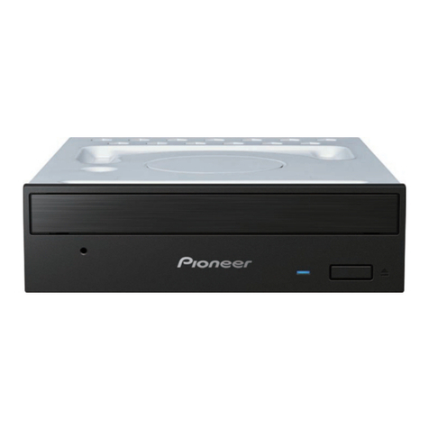
Sony varo PCGA-CD51 User manual

Sony Corporation
XXXXXXX
—XX—
English
99XXXXX-1
Printed in XXXXX
© 1999. X
9-928-323-11 XXXXXXXX
PCGA-CD51
9-928-323-11
CD-ROM DRIVE
SERVICE MANUAL
PCGA-CD51 (U/C)
US Model
Canadian Model
PCGA-CD51 (U/C)99XXXXX-1
9-928-323-11

— 2 —PCGA-CD51 (U/C)
Information in this document is subject to change without
notice.
Sony and VAIO are trademarks of Sony. Intel logo and Intel
Inside logo are registered trademarks of Intel Corporation.
Pentium MMX is a trademarks of Intel Corporation. Microsoft,
MS-DOS, Windows, the Windows 95 and Windows 98 logo are
trademarks of Microsoft Corporation.
All other trademarks are trademarks or registered trademarks of
their respective owners. Oter trademarks and trade names may
be used in this document to refer to the entitles claiming the
marks and names or their produces. Sony Corporation disclaims
any proprietary interest in trademarks and trade names other than
its own.
1. Obey precautionary markings and
instructions
Labels and stamps on the cabinet, chassis, and components iden-
tify areas requiring special precautions. Be sure to observe these
precautions, as well as all precautions listed in the operating
manual and other associated documents.
2. Use designated parts only
The set’s components possess important safety characteristics,
such as noncombustibility and the ability to tolerate large
voltages. Be sure that replacement parts possess the same safety
characteristics as the originals.Also remember that the ( mark,
which appears in circuit diagrams and parts lists, denotes com-
ponentsthathaveparticularlyimportantsafety functions; be extra
sure to use only the designated components.
3. Always follow the original design
when mounting parts and routing wires
The original layout includes various safety features, such as in-
clusion of insulating materials (tubes and tape) and the mount-
ing of parts above the printer board. In addition, internal wiring
has been routed and clamped so as to keep it away from hot or
high-voltage parts. When mounting parts or routing wires. there-
fore, be sure to duplicate the original layout.
Caution Markings for Lithium/Ion Battery - The following or
similar texts shall be provided on battery pack of equipment or
in both the operating and the service instructions.
CAUTION:Dangerofexplosionif battery isincorrectlyreplaced.
Replace only with the same or equivalent type recommended by
the manufacturer. Discard used batteries according to the manu-
facturer’s instructions.
CAUTION: The battery pack used in this device may present a
fire or chemical burn hazard if mistreated. Do not disassemble,
heat above 100˚C (212˚F) or incinerate.
Dispose of used battery promptly.
Keep away from children.
4. Inspect after completing service
After servicing, inspect to make sure that all screws, compo-
nents, and wiring have been returned to their original condition.
Also check the area around the repair location to ensure that
repair work has caused no damage, and confirm safety.
5. When replacing chip components...
Never reuse components.Also remember that the negative side
of tantalum capacitors is easily damaged by heat.
6. When handling flexible print boards...
• Thetemperatureofthesoldering-irontipshouldbeabout270C.
• Do not apply the tip more than three times to the same pattern.
• Handle patterns with care; never apply force.
Caution: Remember that hard disk drives are easily damaged
by vibration.Always handle with care.
Service and Inspection Precautions
†
†
†
†
†
†
†
†
†
†
†
†
†
†
†
†
†
†
†
†
†
†
†
†
†
†
†
†
†
†
†
†
†
†

— 3 — PCGA-CD51 (U/C)
TABLE OF CONTENTS
CHAPTER 1. REMOVAL
1-1. Flowchart ................................................................................................... 1-1
1-2. Electric Parts Arrangement Diagram ......................................................... 1-1
1-3. Removal ..................................................................................................... 1-2
1. Cabinet (Upper) ASSY .............................................................................. 1-2
2. PC Card ASSY ........................................................................................... 1-2
3. IFX-72 Boaed ............................................................................................ 1-3
4. Drive Bezel ASSY, CD-ROM Drive.......................................................... 1-3
5. IFX-73 Board ............................................................................................. 1-4
(to 1-4)
CHAPTER 2. DIAGRAMS
2-1. BLOCK DIAGRAM .................................................................................. 2-1
2-2. MOUNTING DIAGRAM
2-2-1. IFX-68 Board ............................................................................................. 2-1
2-2-2. IFX-72 Board ............................................................................................. 2-2
2-2-3. IFX-73 Bard ............................................................................................... 2-2
2-3. Schematic Diagram
2-3-1. IFX-68........................................................................................................ 2-3
2-3-2. IFX-72........................................................................................................ 2-7
2-3-3. IFX-73...................................................................................................... 2-11
(to 2-14)
CHAPTER 3. EXPLODED VIEW AND PARTS LIST
3-1. Main Unit ................................................................................................... 3-1
3-2. Electlical Parts List .................................................................................... 3-2
3-3. Semiconductor Pin Asignment................................................................... 3-3
(to 3-4)


1-1 PCGA-CD51 (U/C)
CHAPTER 1.
REMOVAL
1-1. Flowchart
• Page x-x indicates the page for the topic.
• Note that HDDs (Hard Disc Drives) are easily damaged by shock of impact.
1-2. Electric Parts Arrangement Diagram
POWER
OFF
Cabinet
(UPPER)
ASSY PC Card
ASSY IFX-72
BOARD
DRIVE
BEZEL
ASSY
IFX-73
BOARD
CD-ROM
DRIVE
P1-2 P1-2 P1-3 P1-4
P1-3
P1-3
PC Card ASSY
CD-ROM Drive IFX-72 Board
IFX-73 Board
Drive Bezel ASSY

1-2PCGA-CD51 (U/C)
1-3. Removal
1. Cabinet (Upper) ASSY
2. PC Card ASSY
1+P 2×8
1+P 2×8
Cabinet (Upper) ASSY
3
2
1+P 2×8
3
2
4Remove the PC Card ASSY
from Bottom of Cabinet.

1-3 PCGA-CD51 (U/C)
3. IFX-72 Boaed
4. Drive Bezel ASSY, CD-ROM Drive
IFX-72 Board
6
7
Insulating
Sheet
5
4
FPC
Shield
1+B 2×3
2+B 2×5
3
When remove
this screw,
pull out the shield.
2+P 2×3
4Insulating Sheet (CD-ROM)
5CD-ROM Drive
3Bracket (CD-ROM)
1The hooks is pushed by driver
in the direction of the arrow,
and remove the Drive bezel ASSY.

1-4PCGA-CD51 (U/C)
5. IFX-73 Board
1+P 2×6
2IFX-73 Board
(END)

2-1 PCGA-CD51 (U/C)
CHAPTER 2.
DIAGRAMS
2-1. BLOCK DIAGRAM
2-2. MOUNTING DIAGRAM
2-2-1. IFX-68 Board
PCMCIA INTERFACE
DATA[15:0]
ADDR[09:0] (16)
(10)
REG#
CE2,1# (2)
INPACK#
WAIT#
IOR#
IOW#
IO16#
IRQ#
OE#
WE#
RST
HREV1.0
PRC1,0
DIVC
(2)
(2)
ATAPI Interface LSI
NP-ATA (TQFP 80pin)
ATD[15:08]
ATD[07:0] (8)
(8)
ATRD#
ATWR#
CS0#,CS1#
ATA0,1,2
ATRST#
IORDY#
INT#
IPT0
OPT0
VALID
CD-ROM DRIVE
Toshiba XM-1902B
AUDIO L/R
LINE OUT
VDD VDD
VDD (Motor)
VDD (Logic)
DC/DC Converter

2-2PCGA-CD51 (U/C)
2-2-2. IFX-72 Board
- A Side -
- B Side -
2-2-3. IFX-73 Bard
- A Side -
- B Side -

PCGA-CD51 (U/C)
IFX-68 (1/2)
2-3. Schematic Diagram
2-3-1. IFX-68
• NOTE :
DNI=Do Not Install
LOCATION
SCHEMATIC
DIAGRAM SHEET
NUMBER
2-42-3

PCGA-CD51 (U/C)
IFX-68 (2/2)
• NOTE :
DNI=Do Not Install
LOCATION
SCHEMATIC
DIAGRAM SHEET
NUMBER
2-5 2-6

PCGA-CD51 (U/C)
IFX-72 (1/2)
• NOTE :
DNI=Do Not Install
LOCATION
SCHEMATIC
DIAGRAM SHEET
NUMBER
2-3-2. IFX-72
2-82-7

PCGA-CD51 (U/C)
IFX-72 (2/2)
• NOTE :
DNI=Do Not Install
LOCATION
SCHEMATIC
DIAGRAM SHEET
NUMBER
2-9 2-10

PCGA-CD51 (U/C)
IFX-73 (1/2)
• NOTE :
DNI=Do Not Install
LOCATION
SCHEMATIC
DIAGRAM SHEET
NUMBER
2-3-3. IFX-73
2-122-11

PCGA-CD51 (U/C)
IFX-73 (2/2)
• NOTE :
DNI=Do Not Install
LOCATION
SCHEMATIC
DIAGRAM SHEET
NUMBER
(END)
2-13 2-14

PCGA-CD51 (U/C)
CHAPTER 3.
EXPLODED VIEW AND PARTS LIST
Note:
• Parts marked by *are not normally in stock.
• Any part that has no part number is not available.
3-1. Main Unit
The components identified by mark or dotted line with
mark are critical for safety.
Replace only with part number specified.
3-23-1
Ref.No.Part No. Description
1 A-8045-546-A PC CARD ASSY
2 A-8056-370-A IFX-72 MOUNT
3 A-8056-371-A IFX-73 MOUNT
4 X-4622-232-1 DRIVE BEZEL ASSY
5 X-4622-244-1 CABINET (UPPER) ASSY
6 1-772-184-11 CD-ROM DRIVE
7 1-791-038-11 FPC (BOARD TO BOARD)
8 4-642-621-01 CABINET (BOTTOM)
9 4-642-623-01 FIX PANEL (CORE)
10 4-642-628-01 FOOT
*11 4-642-629-01 SHIELD
*12 4-642-630-01 BRACKET (CDROM)
13 4-642-631-01 CARD HOLD A
14 4-642-632-01 CARD HOLD B
15 4-642-633-01 INSULATING SHEET
*16 4-642-634-01 REINFORCE BOARD
17 4-643-097-01 INSULATING SHEET (CD ROM)
B1 7-621-772-00 +B 2X3
B2 7-621-772-20 +B 2X5
B3 7-685-104-11 +P 2X6 TYPE 2
B4 7-685-105-19 +P 2X8 TYPE 2
B5 7-685-106-19 +P 2X10 TYPE 2
ACCESSORY & PACKING GROUP
*************************
Ref.No.Part No. Description
3-867-096-11 OPERATION MANUAL (CD-ROM)
4-643-161-01 INSTALL DISK
4-643-429-01 SOFT CASE
A
B
A
B
B3
B3
B1
B4
B2
B3
B3
16
12
3
11
9
15
B1
17
7
4
6
2
8
B5
B5 10
1
5
14
14
13
13
3-2. Electlical Parts List
IFX-68 BOARD
Ref.No.Part No. Description
CN1 1-793-503-21 PC CARD CONNECTOR (68PIN)
CN2 1-793-318-21 16P CONNECTOR
CN3 1-793-319-21 20P CONNECTOR
IC1 8-759-596-58 IC NPATA
IFX-72 BOARD
Ref.No.Part No. Description
CN1 1-793-318-21 16P CONNECTOR
CN3 1-793-319-21 20P CONNECTOR
CN4 1-691-356-21 FFC/FPC CONNECTOR (ZIF) 18P
IFX-73 BOARD
Ref.No.Part No. Description
CN1 1-691-382-21 FFC/FPC CONNECTOR
(0.5MM PITCH) 18P
CN2 1-793-339-11 PHONE JACK
D1 8-719-053-83 SML-310MTT86
D2 8-719-423-30 MA8120-TX
D3 8-719-423-30 MA8120-TX
D4 8-719-423-30 MA8120-TX
D5 8-719-423-30 MA8120-TX
D6 8-719-423-30 MA8120-TX
D7 8-719-423-30 MA8120-TX
D8 8-719-066-98 RB051L-40TE25
IC1 8-759-597-83 RN5RG51AA-TL
IC2 8-759-597-84 RH5RH583B-T1

PCGA-CD51 (U/C)
3-3. Semiconductor Pin Asignment
NPATA (Workbit Corporation)
3-43-3 (END)
Table of contents
Other Sony CD/CDR Drive manuals

Sony
Sony CRX10U User manual

Sony
Sony XDCAM PDW-U1 User manual

Sony
Sony CRX230AD User manual

Sony
Sony CRX1600L User manual

Sony
Sony VPCS1 Series Guide

Sony
Sony CDU701 User manual

Sony
Sony MO DISK DRIVE SMO-F551 User manual

Sony
Sony CDU33A Series User manual

Sony
Sony ODS-D55U User manual

Sony
Sony SDX-D700C Manual