manuals.online logo
Brands
  1. Home
  2. •
  3. Brands
  4. •
  5. Sony
  6. •
  7. Digital Camera
  8. •
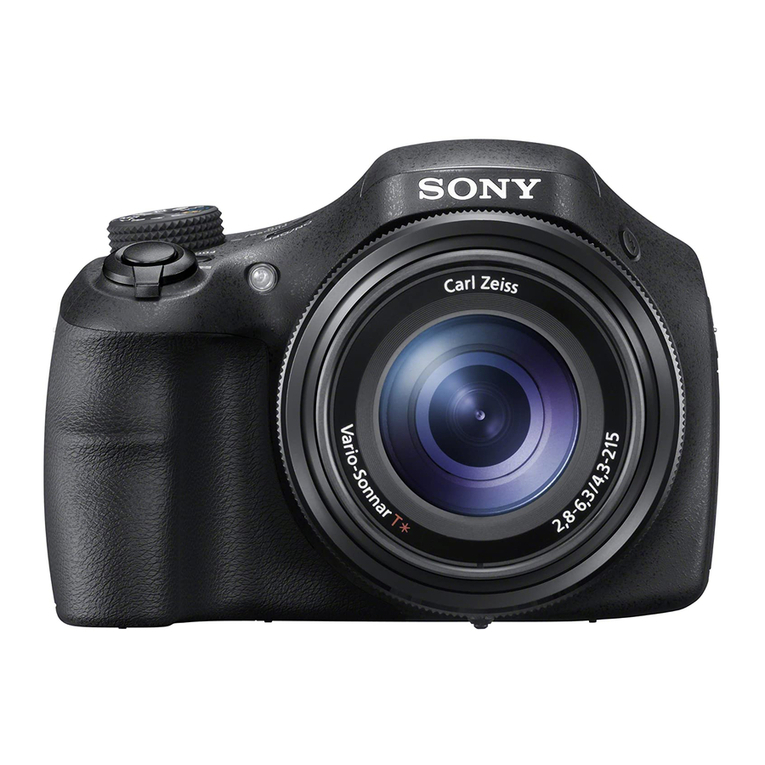
  9. Sony Cyber-shot DSC-HX300 User manual

Sony Cyber-shot DSC-HX300 User manual

DSC-HX300_L2 Sony Corporation
SERVICE MANUAL
Revision History
SERVICE NOTE (Check the following note before the service.)
LEVEL 2
Published by Sony Techno Create Corporation
983472532.pdf
Ver. 1.1 2013.05
DIGITAL STILL CAMERA
The components identified by
mark 0or dotted line with mark
0are critical for safety.
Replace only with part number
specified.
Les composants identifiés par
une marque 0sont critiques pour
la sécurité.
Ne les remplacer que par une piè-
ce portant le numéro spécifié.
US Model
Canadian Model
AEP Model
UK Model
Russian Model
E Model
Australian Model
Hong Kong Model
Chinese Model
Korea Model
Brazilian Model
Japanese Model
Tourist Model
9-834-725-32
DSC-HX300
Ver. Date History Contents S.M. Rev.
issued
1.0 2013.02 Official Release — —
1.1 2013.05 Revised-1
(A1 13-010)
• Change of SERVICE NOTE.
Page 1-12, 1-14
• Change of REPAIR PARTS LIST.
Page 2-6
Yes
2013E08-1
© 2013.05
– ENGLISH –
1-1. PRECAUTION ON REPLACING THE SY-1016 BOARD
1-2. ADDITION OF DESTINATION DATA FILE
1-3. METHOD FOR COPYING OR ERASING THE DATA IN INTERNAL MEMORY
1-4. HOW TO WRITE DATA TO INTERNAL MEMORY
1-5. SELF-DIAGNOSIS FUNCTION
1-6. PROCESS AFTER FIXING FLASH ERROR
1-7. ORNAMENTAL PLATE REPLACING METHOD
1-8. 2ND ASSY REPLACING METHOD
1-9. FINAL INSPECTION
‒JAPANESE‒
1-1. SY-1016基板交換時の注意
1-2. DestinationDataファイルの追加について
1-3. 内蔵メモリーのデータコピーおよび消去方法
1-4. 内蔵メモリーへデータを書き戻す方法
1-5. 自己診断機能
1-6. フラッシュエラー発生時の対処法
Internal memory
ON BOARD
Internal memory
ON BOARD
Revised-1
Replace the previously issued
SERVICE MANUAL 9-834-725-31
with this Manual.
DSC-HX300_L2
– 2 –
SPECIFICATIONS 概略仕様
– ENGLISH – – JAPANESE –
Camera
[System]
Image device: 7.82 mm (1/2.3 type)
Exmor R CMOS sensor
Total pixel number of camera:
Approx. 21.1 Megapixels
Effective pixel number of camera:
Approx. 20.4 Megapixels
Lens: Carl Zeiss Vario-Sonnar T* 50×
zoom lens
f = 4.3 mm – 215 mm (24 mm –
1 200 mm (35 mm film equivalent))
F2.8 (W) – F6.3 (T)
While shooting movies (16:9):
26.5 mm – 1 325 mm*
While shooting movies (4:3):
32.5 mm – 1 625 mm*
* When [Movie SteadyShot] is set
to [Standard]
SteadyShot: Optical
Exposure control: Automatic exposure,
Shutter speed priority, Aperture
priority, Manual exposure, Scene
Selection
White balance: Automatic, Daylight,
Cloudy, Fluorescent 1/2/3,
Incandescent, Flash, One Push,
White Balance Shift
File format:
Still images: JPEG (DCF, Exif,
MPF Baseline) compliant, DPOF
compatible
3D still images: MPO (MPF
Extended (Disparity Image))
compliant
Movies (AVCHD format):
AVCHD format Ver.2.0
compatible
Video: MPEG-4 AVC/H.264
Audio: Dolby Digital 2ch,
equipped with Dolby Digital Stereo
Creator
• Manufactured under license from Dolby
Laboratories.
Movies (MP4 format):
Video: MPEG-4 AVC/H.264
Audio: MPEG-4 AAC-LC 2ch
Recording media: Internal Memory
(Approx. 48 MB), “Memory Stick
Duo” media, “Memory Stick
Micro” media, SD cards, microSD
memory cards
Flash: Flash range (ISO sensitivity
(Recommended Exposure Index)
set to Auto):
Approx. 0.5 m to 8.5 m
(1 ft. 7 3/4 inches to 27 ft.
10 3/4 inches) (W)/
Approx. 2.4 m to 3.5 m
(7 ft. 10 1/2 inches to 11 ft.
5 7/8 inches) (T)
[Input and Output connectors]
HDMI connector: HDMI micro jack
Multi/Micro USB Terminal*:
USB communication
USB communication: Hi-Speed USB
(USB 2.0)
* Supports Micro USB compatible device.
[Screen]
LCD screen: 7.5 cm (3.0 type) TFT
drive
Total number of dots: 921 600 dots
[Power, general]
Power: Rechargeable battery pack
NP-BX1, 3.6 V
AC Adaptor AC-UB10/UB10B/
UB10C/UB10D, 5 V
Power consumption:
Approx. 1.3 W (during shooting
with the LCD screen)
Approx. 1.1 W (during shooting
with the viewfinder)
Operating temperature: 0 °C to 40 °C
(32 °F to 104 °F)
Storage temperature: –20 °C to +60 °C
(–4 °F to +140 °F)
Dimensions (CIPA compliant):
129.6 mm × 93.2 mm × 103.2 mm
(5 1/8 inches × 3 3/4 inches ×
4 1/8 inches) (W/H/D)
Mass (CIPA compliant) (including NP-
BX1 battery pack, “Memory Stick
Duo” media):
Approx. 650 g (1 lb 6.9 oz)
Microphone: Stereo
Speaker: Monaural
Exif Print: Compatible
PRINT Image Matching III:
Compatible
AC Adaptor AC-UB10/UB10B/
UB10C/UB10D
Power requirements: AC 100 V to
240 V, 50 Hz/60 Hz, 70 mA
Output voltage: DC 5 V, 0.5 A
Operating temperature: 0 °C to 40 °C
(32 °F to 104 °F)
Storage temperature: –20 °C to +60 °C
(–4 °F to +140 °F)
Dimensions:
Approx. 50 mm × 22 mm × 54 mm
(2 inches × 7/8 inches × 2 1/4 inches)
(W/H/D)
Mass:
For the USA and Canada: Approx.
48 g (1.7 oz)
For countries or regions other than
the USA and Canada: Approx. 43 g
(1.5 oz)
Rechargeable battery pack
NP-BX1
Used battery: Lithium-ion battery
Maximum voltage: DC 4.2 V
Nominal voltage: DC 3.6 V
Maximum charge voltage: DC 4.2 V
Maximum charge current: 1.89 A
Capacity: 4.5 Wh (1 240 mAh)
Design and specifications are subject to
change without notice.
本体
[システム]
撮像素子:7.82 mm(1/2.3型)
Exmor R CMOSセンサー
総画素数:約2110万画素
カメラ有効画素数:約2040万画素
レンズ:カールツァイス バリオ・ゾナー
T
*50倍ズームレンズ
f=4.3 mm 〜215 mm
(24 mm 〜1 200 mm(35 mm
フィルム換算値))、F2.8(W)〜 F6.3(T)
動画撮影時(16:9):26.5 mm 〜1 325 mm*
動画撮影時(4:3):32.5 mm 〜1 625 mm*
*[動画手ブレ補正]が[スタンダード]のとき
手ブレ補正:光学式
露出制御:自動、シャッタースピード優先、
絞り優先、マニュアル露出、
シーンセレクション
ホワイトバランス:オート、太陽光、曇天、
蛍光灯1/2/3、電球、フラッシュ、
ワンプッシュ、ホワイトバランスシフト
記録方式:
静止画記録方式:
JPEG(DCF、Exif、MPF Baseline)準拠、
DPOF対応
3D静止画記録方式:MPO
(MPF Extended(立体視))準拠
動画記録方式(AVCHD方式):
AVCHD規格 Ver.2.0準拠
映像:MPEG-4 AVC/H.264
音声:Dolby Digital 2ch
ドルビーデジタルステレオクリエーター搭載
•ドルビーラボラトリーズからの実施権に基づき製
造されています。
動画記録方式(MP4方式):
映像:MPEG-4 AVC/H.264
音声:MPEG-4 AAC-LC 2ch
記録メディア:内蔵メモリー 約48MB、
メモリースティック デュオ、
メモリースティック マイクロ、
SDカード、microSDメモリーカード
フラッシュ:撮影範囲(ISO感度
(推奨露光指数)がオートのとき)
約0.5 m〜 8.5 m(W)/
約2.4 m〜 3.5 m(T)
[入出力端子]
HDMI端子:HDMIマイクロ端子
マルチ/マイクロUSB端子*:USB通信
USB通信:Hi-Speed USB(USB 2.0)
*この商品にはマイクロUSB規格に対応した機器をつ
なぐことができます。
[モニター]
液晶モニター:
7.5 cm(3.0型)、TFT駆動
総ドット数:921 600ドット
[電源・その他]
電源:リチャージャブルバッテリー
パックNP-BX1、3.6 V
ACアダプター AC-UB10/UB10B/
UB10C/UB10D、5 V
消費電力:約1.3 W(液晶モニターで撮影時):
1.1W(ファインダーで撮影時)
動作温度:0 ℃〜 40 ℃
保存温度:−20 ℃〜 +60 ℃
外形寸法(CIPA準拠):
129.6 mm×93.2 mm×103.2 mm
(幅×高さ×奥行き)
本体質量(CIPA準拠)(バッテリー
NP-BX1、
メモリースティック デュオを含む):
約650 g
マイクロホン:ステレオ
スピーカー:モノラル
Exif Print:対応
PRINT Image Matching III:対応
ACアダプター
AC-UB10/UB10B/UB10C/
UB10D
定格入力:AC 100 V 〜240 V、
50 Hz/60 Hz、70 mA
定格出力:DC 5 V、0.5 A
動作温度:0 ℃〜 40 ℃
保存温度:−20 ℃〜 +60 ℃
外形寸法:約50 mm×22 mm×54 mm
(幅×高さ×奥行き)
本体質量:約48 g
リチャージャブルバッテリーパック
NP-BX1
使用電池:リチウムイオン蓄電池
最大電圧:DC 4.2 V
公称電圧:DC 3.6 V
容量:4.5 Wh(1 240 mAh)
本機や付属品の仕様および外観は、改良のため予告
なく変更することがありますが、ご了承ください。
Model information table
Model DSC-HX300
Destination US, CND, E, KR, BR, J AEP, UK, RU, E, AUS, HK, CH, JE
Color system NTSC PAL
GPS – –
• Abbreviation
AUS : Australian model
BR : Brazilian model
CH : Chinese model
CND : Canadian model
HK : Hong Kong model
J : Japanese model
JE : Tourist model
KR : Korea model
RU : Russian model
DSC-HX300_L2
– 3 –
SAFETY-RELATED COMPONENT WARNING!!
COMPONENTS IDENTIFIED BY MARK 0OR DOTTED LINE WITH
MARK 0ON THE SCHEMATIC DIAGRAMS AND IN THE PARTS LIST
ARE CRITICAL TO SAFE OPERATION. REPLACE THESE COMPO-
NENTS WITH SONY PARTS WHOSE PART NUMBERS APPEAR AS
SHOWN IN THIS MANUAL OR IN SUPPLEMENTS PUBLISHED BY
SONY.
ATTENTION AU COMPOSANT AYANT RAPPORT
À LA SÉCURITÉ!
LES COMPOSANTS IDENTIFIÉS PAR UNE MARQUE 0SUR LES
DIAGRAMMES SCHÉMATIQUES ET LA LISTE DES PIÈCES SONT
CRITIQUES POUR LA SÉCURITÉ DE FONCTIONNEMENT. NE REM-
PLACER CES COMPOSANTS QUE PAR DES PIÈCES SONY DONT
LES NUMÉROS SONT DONNÉS DANS CE MANUEL OU DANS LES
SUPPLÉMENTS PUBLIÉS PAR SONY.
Caution
Danger of explosion if battery is incorrectly replaced.
Replace only with the same or equivalent type.
Dispose of used batteries according to the instructions.
注意
電池の交換は,正しく行わないと破裂する恐れがあります。
電池を交換する場合には必ず同じ型名の電池又は同等品と
交換してください。
使用済み電池は,取扱指示に従って処分してください。
UNLEADED SOLDER
This unit uses unleaded solder.
Boards requiring use of unleaded solder are printed with the lead free
mark (LF) indicating the solder contains no lead.
(Caution: Some printed circuit boards may not come printed with the
lead free mark due to their particular size.)
: LEAD FREE MARK
Be careful to the following points to solder or unsolder.
• Set the soldering iron tip temperature to 350 °C approximately.
If cannot control temperature, solder/unsolder at high temperature
for a short time.
Caution: The printed pattern (copper foil) may peel away if the
heated tip is applied for too long, so be careful!
Unleaded solder is more viscous (sticky, less prone to
flow) than ordinary solder so use caution not to let solder
bridges occur such as on IC pins, etc.
• Be sure to control soldering iron tips used for unleaded solder and
those for leaded solder so they are managed separately. Mixing un-
leaded solder and leaded solder will cause detachment phenomenon.
SAFETY CHECK-OUT
After correcting the original service problem, perform the following
safety checks before releasing the set to the customer.
1. Check the area of your repair for unsoldered or poorly-soldered
connections. Check the entire board surface for solder splashes and
bridges.
2. Check the interboard wiring to ensure that no wires are “pinched”
or contact high-wattage resistors.
3. Look for unauthorized replacement parts, particularly transistors,
that were installed during a previous repair. Point them out to the
customer and recommend their replacement.
4. Look for parts which, through functioning, show obvious signs of
deterioration. Point them out to the customer and recommend their
replacement.
5. Check the B+ voltage to see it is at the values specified.
6. Flexible Circuit Board Repairing
• Set the soldering iron tip temperature to 350 °C approximately.
• Do not touch the soldering iron on the same conductor of the circuit
board (within 3 times).
• Be careful not to apply force on the conductor when soldering or
unsoldering.
1. 注意事項をお守りください。
 サービスのとき特に注意を要する個所については,キャビ
ネット,シャーシ,部品などにラベルや捺印で注意事項を
表示しています。これらの注意書き及び取扱説明書等の注
意事項を必ずお守り下さい。
2. 指定部品のご使用を
 セットの部品は難燃性や耐電圧など安全上の特性を持った
ものとなっています。従って交換部品は,使用されていた
ものと同じ特性の部品を使用して下さい。特に回路図,部
品表に0印で指定されている安全上重要な部品は必ず指定
のものをご使用下さい。
3. 部品の取付けや配線の引きまわしはもとどおりに
 安全上,チューブやテープなどの絶縁材料を使用したり,
プリント基板から浮かして取付けた部品があります。また
内部配線は引きまわしやクランパによって発熱部品や高圧
部品に接近しないよう配慮されていますので,これらは必
ずもとどおりにして下さい。
4. サービス後は安全点検を
 サービスのために取外したネジ,部品,配線がもとどおり
になっているか,またサービスした個所の周辺を劣化させ
てしまったところがないかなどを点検し,安全性が確保さ
れていることを確認して下さい。
5. チップ部品交換時の注意
 ・ 取外した部品は再使用しないで下さい。
 ・ タンタルコンデンサのマイナス側は熱に弱いため交換時
は注意して下さい。
6. フレキシブルプリント基板の取扱いについて
 ・ 半田こてのこて先温度は約350℃に設定してください。
 ・ 同一パターンに何度もコテ先を当てないで下さい。(3回
以内)
 ・ パターンに力が加わらないよう注意して下さい。
サービス,点検時には次のことにご注意ください。
無鉛半田について
本機には無鉛半田が使用されています。
無鉛半田を使用している基板には,無鉛(LeadFree)を意味する
レッドフリーマークがプリントされています。
(注意:基板サイズによっては,無鉛半田を使用していてもレッ
ドフリーマークがプリントされていないものがありま
す)
:レッドフリーマーク
無鉛半田は,下記の点に注意して使用してください。
・
半田こてのこて先温度は約350℃に設定してください。
温度調節が無理な場合は,高温短時間で作業を行ってくだ
さい。
注意:半田こてを長く当てすぎると,基板のパターン(銅
箔)がはがれてしまうことがありますので,注意して
ください。また,従来の半田よりも粘性が強いため,
IC端子などが半田ブリッジしないように注意してく
ださい。
・
半田こてのこて先は,必ず無鉛半田用と有鉛半田用に分け
て管理してください。
無鉛半田と有鉛半田が混在すると剥離現象が発生してしま
います。
– ENGLISH – – JAPANESE –
DSC-HX300_L2
1-1
1. SERVICE NOTE
1-1. PRECAUTION ON REPLACING THE SY-1016 BOARD
DESTINATION DATA
When you replace to the repairing board, the written destination data of repairing board also might be changed to original setting.
Start the Adjust Manual in the Adjust Station and execute the “DESTINATION DATA WRITE”.
RESTORE DATA
When you replace to the repairing board, get the data from the former one.
Start the Adjust Manual in the Adjust Station and perform “RESTORE DATA” to get the data.
The data getting for this model is as follows.
• PRODUCT ID & USB SERIAL No.
• AWB standard data input & check, Color reproduction check
USB Serial No. and Product ID
The unit is shipped after an ID (USB Serial No.) unique to each unit and an ID (Product ID) unique to each model have been written.
These IDs have not been written in a new board for service, and therefore they must be entered after the board replacement.
After the board has been replaced with a board for service, start the Adjust Manual in the Adjust Station and execute the “PRODUCT ID & USB
SERIAL No. INPUT” and enter these IDs.
Note: A newly entered Product ID is not always equal to the ID before board replacement. If the new ID differs from the previous ID, it may cause a difference
from the ID registered by the customer.
Angular Velocity Sensor
When you replace to the repairing board, write down the sensitivity displayed on the angular velocity sensor (SE401).
Start the Adjust Manual in the Adjust Station and execute the “Angular velocity sensor sensitivity adj”.
SY-1016 BOARD (SIDE A)
SE401 Y P
Y P
P: PITCH sensor sensitivity
Y: YAW sensor sensitivity
Type B:
Type A:
Note: The sensor sensitivity of SE401 of SY-1016 board is written only repair parts.
– ENGLISH –
1-2. ADDITION OF DESTINATION DATA FILE
If the Destination Data file included in the Adjust manual is old, “DESTINATION DATA WRITE” cannot be executed in some cases.
In that case, download a new Destination Data file from the TISS homepage according to the following procedure.
Note 1: To perform Destination Data Write for this model, the Adjust manual of the DSC-WX50 series must have been installed.
Install the Adjust manual of the DSC-WX50 series in advance.
Note 2: The actual image may differ from the image shown above.
1) If the Destination Data file in the Adjust manual in use is old, the window shown in Fig. 1 is displayed.
Click the [OK] button.
Fig. 1
2) The Destination Data Write window opens.
Check the version of the Destination Data file retained in the Adjust manual.
Destination Ver. window
DSC-HX300_L2
1-2
3) Search the model whose new Destination Data file you want to get on the TISS homepage.
When the Destination Data file has been updated, a file with a name “Destination File For ‘model name’.zip” is registered.
(Example) Destination File For DSC-WX50.zip
Furthermore, the version supported by the Destination Data file is shown in the Remarks column.
Note : If the Destination Data file has not been updated, contact the Service Headquarters.
4) Download the Destination Data file of the relevant model and unzip the file.
5) Execute “DESTINATION DATA WRITE” in the Adjust tab of the Adjust manual.
Click the [START] button.
6) Click the [File Update] button in the window.
7) A file selection screen opens. Select the Destination Data file to be added and click the [Open] button.
8) When the file has been successfully added, the following window opens.
9) Check the Destination Ver. window and confirm that the version has been updated.
Destination Ver. window
– ENGLISH –
DSC-HX300_L2
1-3
– ENGLISH –
1-3. METHOD FOR COPYING OR ERASING THE DATA IN INTERNAL MEMORY
The data can be copied/erased by the operations on the MENU. (When erasing the data, execute formatting the internal memory.)
Note 1:When replacing the SY-1016 board, erase the data in internal memory of the board before replacement.
Note 2:When replacing the SY-1016 board, execute formatting and initialize the internal memory after replacement.
Method for Copying the Data in Internal Memory
Copy
Copies all images in the internal memory to a memory card.
1. Insert a memory card with sufficient free capacity into the camera.
2. MENU (Settings) (Memory Card Tool) [Copy] [OK]
Notes
Use a fully charged battery pack. If you attempt to copy image files using a battery pack with little
remaining charge, the battery pack may run out, causing copying to fail or possibly corrupting the
data.
Images cannot be copied individually.
The original images in the internal memory are retained even after copying. To delete the contents
of the internal memory, remove the memory card after copying, then format the internal memory
([Format] in [Internal Memory Tool]).
The data will be copied to the recording folder that is currently being used, with a number one
higher than the largest data number in that folder.
Method for Formatting the Internal Memory or Memory Card media
Format
Formats the memory card or the internal memory.
When you use a memory card with this camera for the first time, it is recommended to format the card
using the camera for stable performance of the memory card before shooting. Note that formatting
permanently erases all data on the memory card, and is unrecoverable. Save precious data on a
computer, etc.
1. MENU (Settings) (Memory Card Tool) or (Internal Memory Tool) [Format]
[OK]
Notes
Note that formatting permanently erases all data including even protected images.
1-4. HOW TO WRITE DATA TO INTERNAL MEMORY
Usually, the camera has been set so as to disable the data writing from the PC to the internal memory of the camera.
This setting must be changed temporarily when the data is to be written to the internal memory such as a case after the board replacement.
To change settings is enabled with using the writing enabler tool (Write Enable Tool) on the Adjust Manual is activating from the Adjust Station.
Data writing method
1) Start the Adjust Manual from the Adjust Station.
2) Click (Write Enable Tool) button.
3) Click “Activate Write Enable Mode” button.
4) Upon completion of the setting change, the following message will be displayed.
5) Return the driver to the original one, and connect the PC to the camera (USB mode: Mass Storage).
6) Write the data read out into the PC to the internal memory of the camera.
7) Disconnect the PC from the camera, and turn off the camera.
Note: By turning off the camera, the write enable setting is reset.
DSC-HX300_L2
1-4
– ENGLISH –
1-5. SELF-DIAGNOSIS FUNCTION
1-5-1. Self-diagnosis Function
When problems occur while the unit is operating, the self-diagnosis func-
tion starts working, and displays on the LCD screen what to do.
Details of the self-diagnosis functions are provided in the Instruction
manual.
1-5-2. Self-diagnosis Display
When problems occur while the unit is operating, the LCD screen shows
a 4-digit display consisting of an alphabet and numbers, which blinks at
3.2 Hz. This 5-character display indicates the “repaired by:”, “block” in
which the problem occurred, and “detailed code” of the problem.
0 0
3 2C
Repaired by:
Refer to “1-5-3. Self-diagnosis Code Tabl e”.
Indicates the appropriate
step to be taken.
E.g.
13 ....Format the “memory card”.
32 ....Turn on power again.
Block Detailed Code
Blinks at 3.2 Hz
C : Corrected by customer
E : Corrected by service
engineer
LCD screen
1-5-3. Self-diagnosis Code Table
Self-diagnosis Code
Symptom/State Correction
Repaired by:
Block
Function
Detailed
Code
C1 3 0 1
The internal memory has experienced a me-
dia error. Turn the power off and on again.
The internal memory has experienced a for-
mat error. Format the internal memory.
Memory card is unformatted. Format the memory card.
Memory card is broken. Insert a new memory card.
Memory card type error Insert a supported memory card.
The camera cannot read or write dataon the
memory card.
Turn the power off and on again, or taking out and inserting the memory
card several times.
C3 2 0 1
Trouble with hardware Turn the power off and on again.
C
E
32
61
60
00
Difficult to adjust focus
(Cannot initialize focus)
Retry turn the power on by the power switch. If it does not recover,
check the focus reset sensor of lens block (pin qh, qk of CN402 on the
SY-1016 board). If it is OK, check the focus motor drive IC (IC403
on the SY-1016 board).
E4 1 0 0
Abnormality of network control. Turn power off and turn power on again.
E6 1 1 0
Zoom operations fault
(Cannot initialize zoom lens.)
Retry turn the power on by the power switch. Check the zoom reset
sensor of lens block (pin qf of CN402 on the SY-1016 board) when
zooming is performed when the zoom button is operated. If it is OK,
check the zoom motor drive IC (IC403 on the SY-1016 board).
E6 1 3 0
Reset position detection error on the stepper
iris initializing Turn power off and turn power on again.
E6 2 0 2
Abnormality of IC for steadyshot. Check or replacement of the IC for steadyshot (IC403 on the SY-1016
board).
E6 2 1 0
Lens initializing failure. Check or replacement of the IC for steadyshot (IC403 on the SY-1016
board).
E6 2 1 1
Lens overheating (PITCH).
Check the HALL element (PITCH) of optical image stabilizer (pin wj,
wk of CN402 on the SY-1016 board). If it is OK, check PITCH angular
velocity sensor (SE401 on the SY-1016 board) peripheral circuits.
E6 2 1 2
Lens overheating (YAW).
Check the HALL element (YAW) of optical image stabilizer (pin e;,
ea of CN402 on the SY-1016 board). If it is OK, check YAW angular
velocity sensor (SE401 on the SY-1016 board) peripheral circuits.
E6 2 2 0
Abnormality of thermistor. Check the temp sensor of optical image stabilizer (pin qs of CN402
on the SY-1016 board).
E9 1 0 1
Abnormality when flash is being charged. Checking of flash unit or replacement of flash unit. (Note 1)
E9 2 0 0
Battery / Dry cell distinction defect Turn power off and turn power on again.
E9 4 0 0
Internal memory fault Inspect the internal memory (IC201 on the SY-1016 board).
E9 5 0 0
GPS hardware error Turn power off and turn power on again.
E9 5 0 1
Acceleration sensor hardware error Turn power off and turn power on again.
E9 5 0 2
Electronic compass hardware error
(GPS hardware error) Turn power off and turn power on again.
Note 1: After repair, be sure to perform “1-6. PROCESS AFTER FIXING FLASH ERROR”.
Note 2: Functions of codes with * mark are not provided in this unit.
*
*
*
*
( )
DSC-HX300_L2
1-5
1-6. PROCESS AFTER FIXING FLASH ERROR
When “FLASH error” (Self-diagnosis Code E : 91 : 01) occurs, to prevent any abnormal situation caused by high voltage, setting of the flash is changed
automatically to disabling charge and flash setting.
After fixing, this setting needs to be deactivated.
Method for Initializing the Flash Error Code
Reset Flash Error using the Flash Error Repair Tool Ver_[].[].exe.
– ENGLISH – – JAPANESE –
1-1. SY-1016基板交換時の注意
仕向けデータ
補修用基板と交換する時,補修用基板に書かれている仕向けデータは元の設定と違っている場合があります。
AdjustStationからAdjustManualを起動させて「DESTINATIONDATAWRITE」を実行させてください。
リストアデータ
補修用基板と交換する時,交換前の基板よりデータを取得してください。
データの取得はAdjustStationからAdjustManualを起動させて「RESTOREDATA」を実行させてください。
本機で取得されるデータは下記になります。
・PRODUCTID&USBSERIALNo.
・AWBstandarddatainput&check,Colorreproductioncheck
USBシリアルNo.およびプロダクトIDについて
本機はセット固有のID(USBシリアルNo.)と機種固有のID(プロダクトID)を書き込んだ後に出荷されています。
新品の補修用基板にはこれらのIDが書き込まれていないため,基板交換後にIDを入力する必要があります。
補修用基板に交換した後はAdjustStationからAdjustManualを起動し,「PRODUCTID&USBSERIALNo.INPUT」を実行させてIDを入
力してください。
Note: 新しくプロダクトIDを入力すると,必ずしも基板交換前のIDと同じIDになるとは限りません。新しいIDと元のIDが違う場合にはお客様がユーザー登録さ
れているIDと相違が出てしまう可能性があります。
角速度センサ
補修用基板と交換する時,角速度センサ(SE401)の感度表示を書き留めてください。
AdjustStationからAdjustManualを起動させて「Angularvelocitysensorsensitivityadj」を実行させてください。
SY-1016 BOARD (SIDE A)
SE401 Y P
Y P
Type B:
Type A:
P: PITCH感度表示
Y: YAW感度表示
Note:SY-1016基板のSE401感度表示は補修用基板にしか記載されておりません。
DSC-HX300_L2
1-6
– JAPANESE –
1-2. DestinationDataファイルの追加について
Adjustmanualに含まれるDestinationDataファイルが古い場合,「DESTINATIONDATAWRITE」が実行できないことがあります。
その場合は,下記の手順を参考にして,TISSホームページより新しいDestinationDataファイルを入手してください。
Note1: この機種で仕向け設定を行うには,DSC-WX50シリーズのAdjustmanualがインストールされている必要があります。
  先にDSC-WX50シリーズのAdjustmanualをインストールしてください。
Note2: 手順中の画像は実際と異なる場合があります。
1) 使用しているAdjustmanualのDestinationDataファイルが古い場合,Fig.1のようなウインドウが表示される。
 [OK]ボタンをクリックする。


Fig. 1
2) DestinationDataWriteウインドウが表示される。   
 Adjustmanualの保持しているDestinationDataファイルのバージョンを確認する。


Destination Ver. ウインドウ
3) TISSホームページにて,新しいDestinationDataファイルを入手したい機種を検索する。
 Destination Data ファイルが更新されている場合,「DestinationFileFor”機種名”.zip」という名称のファイルが登録されてい
る。
(例)DestinationFileForDSC-WX50.zip
また,Remarks欄にはこのDestinationDataファイルが対応するバージョンが記載されています。
Note:バージョンが更新されていなかった場合は,サービスヘッドクォーターへお問い合わせください。
4) 該当機種のDestinationDataファイルをダウンロードし,解凍する。

5) AdjustmanualのAdjustタブにある,「DESTINATIONDATAWRITE」を実行する。
 [START]ボタンをクリックする。

DSC-HX300_L2
1-7
– JAPANESE –
6) ウインドウ内の[FileUpdate]ボタンをクリックする。


7) ファイルを選択する画面が出るので,追加するDestinationDataファイルを選択し,[開く]ボタンをクリックする。


8) ファイルの追加が成功すると,下記のような画面が出る。


9) DestinationVer.ウインドウを確認し,バージョンが更新されていることを確認する。

Destination Ver. ウインドウ
1-3. 内蔵メモリーのデータコピーおよび消去方法
内蔵メモリーのデータコピーまたは消去はメニュー操作から実行可能です。(消去する場合は内蔵メモリーの初期化を行います。)
Note1:SY-1016基板交換の際は,基板交換前に内蔵メモリーのデータを消去して下さい。
Note2:SY-1016基板交換の際は,基板交換後に内蔵メモリーのフォーマットおよび初期化を実行して下さい。
内蔵メモリーのコピー方法
আش
৔୉ওঔজشஈ઺൸ؚওঔজشش঳ฐআش؛
 ౄী૬ઍ୤ওঔজششমো
 0(18  ق৒ك  قওঔজشششঝك نআشه ن2.ه রఙ
ৠ৒
ି
ౄীౄংজشઞ৷؛ଋ୤૘ংজشઞ৷઺൸ইঝ
আشؚংজشજشૡଛؚش୊௤
؛
઺൸আش؛
شআشؚ৔୉ওঔজش৔شచ௾؛৔୉ওঔজش৔ઍ଎ு
ؚআش৏ওঔজششম৬ؚن৔୉ওঔজششঝهنইش
ঐهষ؛
شআشؚ૔৒ஈইঝ঳୞৏ইঝ୞ಀআش
؛
内蔵メモリー,もしくはメモリーカードのフォーマット方法
ইشঐ
ওঔজششؚ৔୉ওঔজشইشঐق৲ك؛
ওঔজشش৿৒ؚওঔজششমઞৃ়ؚ
ؚমইشঐ؛ইشঐؚওঔজششஈ
৸ش଎ுؚರ؛পજشঃথ৳ோ
؛
 0(18  ق৒ك  قওঔজشششঝكؚ ق৔୉ওঔজششঝك
نইشঐه ن2.ه রఙ ৠ৒
ି
ইشঐؚউট઺൸அؚش଎ுؚರ
؛
DSC-HX300_L2
1-8
– JAPANESE –
1-4 内蔵メモリーへデータを書き戻す方法
通常は,PCからカメラの内蔵メモリへデータを書き込むことはできない設定になっています。
基板交換後などに,内蔵メモリへデータを書き戻す場合には,この設定を一時的に変更する必要があります。
設定の変更は,AdjustStationからAdjustManualを起動させて書き込み許可ツール(WriteEnableTool)を使用します。
書き戻し方法
1) AdjustStationからAdjustManualを起動する。
2) (WriteEnableTool)ボタンをクリックする。
3) “ActivateWriteEnableMode”ボタンをクリックする。

4) 設定の変更が終了すると,次のメッセージが表示されますので“OK”ボタンをクリックする。

5) ドライバを元に戻して,カメラとPCをマスストレージ接続する。
6) PCに読み出しておいたデータをカメラの内蔵メモリに書き込む。
7) カメラとPCの接続を解除し,カメラの電源をOFFにする。
注意:カメラの電源をOFFにすることにより,書き込み許可の設定が解除されます。
1-5. 自己診断機能
1-5-1.自己診断機能について
本機の動作に不具合が生じたとき,自己診断機能が働き,LCD
画面に,どう処置したらよいか判断できる表示を行います。自
己診断機能については取扱説明書にも掲載されて
います。
1-5-2.自己診断表示
本機の動作に不具合が生じたとき,LCD画面にアルファベッ
トと4桁の数字が表示され,3.2Hzで点滅します。この5文字の
表示によって対応者分類および不具合の生じたブロックの分
類,不具合の詳細コードを示します。
0 0
C23
対応者分類
「1‑5‑3.自己診断コード表」を参照
対応方法の違いにより分類
例 
・メモリーカードをフォーマットする・・31
32 ・・・電源を入れ直す
ブロック分類 詳細コード
3.2Hz点滅
C:お客さま自身で対応
E :サービスエンジニア 
で対応
LCD画面
DSC-HX300_L2
1-9
– JAPANESE –
1-5-3.自己診断コード表
自己診断コード
症状/状態 対応/方法
対
応
者
ブロック
機能 詳細
コード
C1 3 0 1
内蔵メモリーにメディアエラーがあっ
た。 電源を入れ直す。
内蔵メモリーにフォーマットエラーが
あった。 内蔵メモリーをフォーマットする。
フォーマットしていないメモリーカー
ドを入れた。 メモリーカードをフォーマットする。
メモリーカードが壊れている。 新しいメモリーカードに交換する。
メモリーカードのタイプエラーを検出
した。 規格内のメモリーカードを挿入する。
メモリーカードが読み/書きできない。 電源の入れ直し,またはメモリーカードの挿し/外しを数回
試す。
C 3 2 0 1 ハードウェアトラブルを検出した。 電源を入れ直す。
C
E
32
61
60
00
フォーカスが合いにくい。
(フォーカスの初期化ができない)
操作スイッチの電源を入れ直す。
復帰しない場合はレンズブロックのフォーカスリセットセン
サ(SY-1016基板CN402qh,qkピン)を点検する。
異常なければフォーカスモータ駆動IC(SY-1016基板IC403)
を点検する。
E 4 1 0 0 ネットワーク制御マイコンの異常。 電源を入れ直す。
E6 11 0
ズーム動作の異常。
(ズームレンズの初期化ができない)
操作スイッチの電源を入れ直す。
ズームボタンを操作したときにズーム動作をすればレンズブ
ロックのズームリセットセンサ(SY-1016基板CN402qfピン)
を点検する。
異常なければズームモータ駆動IC(SY-1016基板IC403)を点
検する。
E6 13 0
ステッパIRISイニシャル時リセット位置
検出異常 電源を入れ直す。
E 6 2 0 2 手振れ補正用ICの異常。 手振れ補正用IC(SY-1016基板IC403)を点検または交換する。
E 6 2 1 0 レンズ初期化異常。 手振れ補正用IC(SY-1016基板IC403)を点検または交換する。
E 6 2 1 1 レンズオーバーヒート(PITCH)
光学手振れ補正ブロックのホール素子(PITCH)(SY-1016基板
CN402wj,wkピン)を点検する。
異常なければPITCH角速度センサ(SY-1016基板SE401)周辺
の回路を点検する。
E 6 2 1 2 レンズオーバーヒート(YAW)
光学手振れ補正ブロックのホール素子(YAW)(SY-1016基板
CN402e;,eaピン)を点検する。
異常なければYAW角速度センサ(SY-1016基板SE401)周辺の
回路を点検する。
E 6 2 2 0 サーミスタの異常。 光学手振れ補正ブロックの温度センサ(SY-1016基板CN402
qsピン)を点検する。
E9 1 0 1 フラッシュの充電異常。 フラッシュユニットを点検または交換する。(Note1)
E 9 2 0 0 バッテリー /乾電池判別不良 電源を入れ直す。
E 9 4 0 0 内蔵メモリーの書き込み/消去動作不良 内蔵メモリー(SY-1016基板IC201)を点検する。
E 9 5 0 0 GPSハードウェア異常 電源を入れ直す。
E 9 5 0 1 加速度センサーハードウェア異常 電源を入れ直す。
E9 50 2
地磁気センサーハードウェア異常
(GPSハードウェア異常) 電源を入れ直す。
Note1:交換後は,必ず「1-6.フラッシュエラー発生時の対処法」を行って下さい。
Note2:*マークのコードは本機には実装されていない機能です。
1-6. フラッシュエラー発生時の対処法
本機はフラッシュエラー(自己診断コードE:91:01)が発生した場合,高電圧による異常を防止するために自動的にフラッシュ充
電および発光禁止の設定になります。
フラッシュエラー発生後はエラーの解除を行う必要があります。
フラッシュエラーの解除方法
FlashErrorRepairToolVer[].[].exeを使用してFlashErrorを解除してください。
*
*
*
()
*
DSC-HX300_L2
1-10
1-7. ORNAMENTAL PLATE REPLACING METHOD
Removal
(1) Pour a solvent such as alcohol from four places A to the tweezers or a needle shown below into a gap of Ornamental Plate.
(2) Remove the Ornamental Plate.
Tweezers
A
A
Ornamental Plate
Solvent
(3) Remove the three screws to detach the Filter Screw Frame Assy.
Filter Screw Frame Assy
Installation
(1) Match the boss of the Filter Screw Frame Assy with the concave of the 1st Frame Assy, install the Filter Screw Frame Assy, and then tighten three
screws.
Filter Screw Frame Assy
1st Frame Assy
Concave
Boss
(2) Peel off the release paper of the Ornamental Plate and stick the Ornamental Plate matching the boss of the Ornamental Plate with the screw A
position.
Ornamental Plate Screw A position
Boss
1-8. 2ND ASSY REPLACING METHOD
Removal
(1) Peel off the Polyester Tape.
(2) Unsolder the Main Flexible Board and the Shutter Flexible Board.
Shutter Flexible Board
Main Flexible Board
Solders
Polyester Tape
(3) Peel off the Shutter Flexible Board.
Adhesive Tape
Shutter Flexible Board
Main Flexible Board
(4) Disconnect the 5th Assy Flexible Board from the connector on the Main Flexible Board.
Main Flexible Board
5th Assy
Flexible Board
DSC-HX300_L2
1-11
(5) Peel the Main Flexible Board off the Fixed Stationary Tube Assy.
Adhesive Tapes
Fixed Stationary Tube Assy
Main Flexible Board
(6) Remove the three screws to detach the Z Motor.
(7) Disconnect the Vibration Absorption Flexible Board from the connector on the Main Flexible Board.
(8) Peel the Main Flexible Board off the Fixed Stationary Tube Assy.
Fixed Stationary
Tube Assy
Main Flexible
Board
Vibration Absorption
Flexible Board
Adhesive Tape
Z Motor
(9) Remove the six screws to detach the Rear Mirror Assy.
Rear Mirror Assy
(10) Turn the Naruto Gear counterclockwise to extend the lens.
(11) Draw the F Flexible Board and the Vibration Absorption Flexible Board inside the Fixed Stationary Tube Assy.
(12) Turn the Naruto Gear clockwise to return the lens to the previous position.
Naruto Gear
F Flexible Board
Vibration Absorption
Flexible Board
Fixed Stationary
Tube Assy
(13) Remove the Naruto Gear.
Naruto Gear
(14) Remove the Fixed Stationary Tube Assy.
Fixed Stationary
Tube Assy
DSC-HX300_L2
1-12
(15) Turn the Cam Tube in the direction of the arrow to detach the 1st Assy.
1st Assy
Cam Tube
(16) Remove the four screws to detach the Bearing Assy and the Straight Tube Thrust Spring.
Bearing Assy
Straight Tube
Thrust Spring
(17) Remove the 4th Assy.
4th Assy
(18) Fully turn the Shafts Retainer Assy in the direction of arrow.
(19) Remove the 3rd Assy.
Note: When removing the 3rd Assy, hold the bottom of the 2nd Assy to prevent it from falling.
3rd Assy
2nd Assy
Shafts Retainer Assy
(20) Remove the Cam Tube Assy.
Cam Tube Assy
The changed portions from
Ver. 1.0 are shown in blue.
Ver. 1.1 2013.05
DSC-HX300_L2
1-13
(21) Remove the five screws to detach the Shafts Retainer Assy and the 2nd Assy.
2nd Assy,
Shafts Retainer Assy
(22) Detach the 2nd Assy from the Shafts Retainer Assy.
Shafts Retainer Assy
2nd Assy
Installation
(1) Attach the 2nd Assy to the Shafts Retainer Assy.
Shafts Retainer Assy
2nd Assy
(2) Match the groove with the hole and attach the Straight Tube to the Cam Tube Assy.
Cam Tube Assy
Straight Tube
Match the groove with the hole
Hole
Groove
(3) Match the boss with the groove, attach the Shafts Retainer Assy and the 2nd Assy to the Straight Tube, and then tighten five screws.
2nd Assy,
Shafts Retainer Assy
Straight Tube
Groove
Boss
DSC-HX300_L2
1-14
(4) Match the boss with the groove and, install the 3rd Assy while inserting the shaft into the hole.
Note: When installing the 3rd Assy, hold the bottom of the 2nd Assy to prevent it from falling.
(5) Fully turn the Shafts Retainer Assy in the direction of arrow.
Hole
Boss
Groove
Shaft
Shafts Retainer Assy
2nd Assy
3rd Assy
(6) Match the boss with the groove and attach the 4th Assy while inserting the shafts into the holes.
Hole
Hole Groove
Boss
Shafts
4th Assy
Shafts Retainer Assy
(7) Install the Bearing Assy and the Straight Tube Thrust Spring while passing the Flexible Boards inside them, and then tighten four screws.
Bearing Assy
Straight Tube
Thrust Spring
(8) Pass the Flexible Boards through the notches of the Straight Tube.
Notch Notch
(9) Match the marks and turn the Cam Tube to be attached to the 1st Assy in the direction of arrow.
1st Assy
Cam Tube
Marks
(10) Install the Cam Tube while matching the Connecting Gear to the groove of the Fixed Stationary Tube Assy.
Connecting Gear
Fixed Stationary
Tube Assy
Groove
The changed portions from
Ver. 1.0 are shown in blue.
Ver. 1.1 2013.05
DSC-HX300_L2
1-15
(11) Attach the Naruto Gear.
Naruto Gear
(12) Turn the Naruto Gear counterclockwise to extend the lens.
(13) Pull the F Flexible Board and the Vibration Absorption Flexible Board out of the Fixed Stationary Tube Assy.
(14) Turn the Naruto Gear clockwise to return the lens to the previous position.
Fix the Vibration Absorption
Flexible Board Fix the F Flexible Board
Fixed Stationary
Tube Assy
(15) Install the Rear Mirror Assy and tighten six screws.
Rear Mirror Assy
(16) Stick the Main Flexible Board to the Fixed Stationary Tube Assy.
(17) Connect the Vibration Absorption Flexible Board to the connector on the Main Flexible Board.
(18) Install the Z Motor and tighten three screws.
Adhesive Tape
Fixed Stationary
Tube Assy
Main Flexible
Board
Vibration Absorption
Flexible Board
Z Motor
(19) Stick the Main Flexible Board to the Fixed Stationary Tube Assy.
Adhesive Tapes
Fixed Stationary Tube Assy
Main Flexible Board
DSC-HX300_L2
1-16
(20) Connect the 5th Assy Flexible Board to the connector on the Main Flexible Board.
Main Flexible Board
5th Assy
Flexible Board
(21) Stick the Shutter Flexible Board.
Adhesive Tape
Shutter Flexible Board
Main Flexible Board
(22) Solder the Main Flexible Board and the Shutter Flexible Board.
(23) Stick the Polyester Tape.
Shutter Flexible Board
Main Flexible Board
Solders
Polyester Tape
1-9. FINAL INSPECTION
1-9-1. Confirm There Is No Fault In Actual Motion/Actual Screen
Inspect it as follows when you exchange parts in the lens block.
1
2
4
5
Zoom motion (Check five postures: horizontal, upward/downward, upper/lower oblique 45º)
No abnormal sound or motion must be found over full stroke between TELE end and WIDE end.
Zoom image
No abnormality such as a skipped image or wavy image must be found in the image through LCD or finder over full stroke between
TELE end and WIDE end.
Appearance condition
Scratches or stains must not be noticeable, except that the customer permits them.
Foreign matters on the lens
The lens condition must not be worse than that when the camera was received from the customer.
Lens at TELE end
Lens at WIDE end Upward
Downward
Horizontal
Full stroke check
下図は当機種と本体の形状が異なります。
Note:
Note:
As for the figure below, this model and the shape
of the main body are different.
DSC-HX300_L2
1-17E
1-9-2. Inspection When Cam Tube Block Assy Or Straight Tube Lubricated Assy Is Replaced
Focus check
1Preparation
• Camera installed re-assemble lens.
• Chart (Printed PDF file at the same magnification) (Refer to <Reference>)
• Tripod
• Mirror (ex. CD)
• Memory card
• PC
2Shoot setting
(1) Paste the chart.
• Chart should be on the flat wall.
• Illuminance level in the chart should be the same.
• Make the tripod’s height and the center of the chart to the same height.
• Enough space needed for shooting.
(2) Set the camera.
• Set [P] mode
• Set [Maximum] size
• Set ISO lowest level
• Set Flash [OFF]
(3) Set the camera on a tripod.
(4) Adjust the position of the camera and the chart.
1. Set the zoom position of the camera at Wide end.
2. Attach the mirror onto the center of the chart.
* The mirror should not tilt on the chart.
3. Set the camera to display the chart on LCD like in the following picture.
4. Adjust the camera position to the center of the chart.
* Adjust the tripod height and the position (Lateral direction).
5. Adjust the camera angle to the frame of the chart with tripod.
Remove the mirror.
3Shooting
(1) Set [Self-Timer]
(2) Shot
4Check the shot image.
(1) Check the shot image on PC.
100% Display (Display at the same magnification of its Pixel.)
Compare the image with the sample you set.
No extreme focus blurring
It should be distinguished the black and white by the sharpness between them.
If it is in NG level, replace the lens unit.
<Reference>
• How to Print the Chart
Print “Focus-Chart_A3.pdf” with printer.
Print at the same magnification (It means 100 % size).
Check the settings of printer to print in proper size.
• Check of chart size.
Make charts together and check if the size of charts is the following size.
* The chart consists of 2 pcs.

Other manuals for Cyber-shot DSC-HX300

6

Other Sony Digital Camera manuals

Sony Handycam DCR-SX22E Installation instructions manual

Sony

Sony Handycam DCR-SX22E Installation instructions manual

Sony ILCE-6100 User manual

Sony

Sony ILCE-6100 User manual

Sony Cyber-shot DSC-H200 User manual

Sony

Sony Cyber-shot DSC-H200 User manual

Sony Cyber-shot DSC-WX100 User manual

Sony

Sony Cyber-shot DSC-WX100 User manual

Sony Cyber-shot DSC-T70 User manual

Sony

Sony Cyber-shot DSC-T70 User manual

Sony ZV-1 User guide

Sony

Sony ZV-1 User guide

Sony ZV-E10 User manual

Sony

Sony ZV-E10 User manual

Sony BURANO MPC-2610 User manual

Sony

Sony BURANO MPC-2610 User manual

Sony Cyber-shot DSC-HX5 User manual

Sony

Sony Cyber-shot DSC-HX5 User manual

Sony Cyber-shot DSC-S600 User manual

Sony

Sony Cyber-shot DSC-S600 User manual

Sony DSLR-A100 User manual

Sony

Sony DSLR-A100 User manual

Sony BKMA-510HD User manual

Sony

Sony BKMA-510HD User manual

Sony Mavica MVC-FD81 User manual

Sony

Sony Mavica MVC-FD81 User manual

Sony Alpha SLT-A99V User manual

Sony

Sony Alpha SLT-A99V User manual

Sony Cyber-shot DSC-TX55 User manual

Sony

Sony Cyber-shot DSC-TX55 User manual

Sony a7CII User guide

Sony

Sony a7CII User guide

Sony DSC-TX9 Cyber-shot® Quick start guide

Sony

Sony DSC-TX9 Cyber-shot® Quick start guide

Sony Cyber-shot DSC-S600 User manual

Sony

Sony Cyber-shot DSC-S600 User manual

Sony Cyber-shot DSC-RX0 Reference guide

Sony

Sony Cyber-shot DSC-RX0 Reference guide

Sony DSC-HX60 User manual

Sony

Sony DSC-HX60 User manual

Sony Cyber-Shot DSC-HX10V User manual

Sony

Sony Cyber-Shot DSC-HX10V User manual

Sony DSC-W130/B User manual

Sony

Sony DSC-W130/B User manual

Sony Cyber-shot DSC-W730 Installation instructions manual

Sony

Sony Cyber-shot DSC-W730 Installation instructions manual

Sony A900 - Alpha 24.6MP DSLR Camera User manual

Sony

Sony A900 - Alpha 24.6MP DSLR Camera User manual

Popular Digital Camera manuals by other brands

Epson r-d1 - Rangefinder Digital Camera Brochure & specs

Epson

Epson r-d1 - Rangefinder Digital Camera Brochure & specs

Mustek MDC-800 user manual

Mustek

Mustek MDC-800 user manual

Sanyo Xacti VPC-S1 Service manual

Sanyo

Sanyo Xacti VPC-S1 Service manual

Wildlife Monitoring Solutions Wilsus Tradenda 4G Wireless user manual

Wildlife Monitoring Solutions

Wildlife Monitoring Solutions Wilsus Tradenda 4G Wireless user manual

Nikon Coolpix 55200 quick start guide

Nikon

Nikon Coolpix 55200 quick start guide

FujiFilm FinePix A201 owner's manual

FujiFilm

FujiFilm FinePix A201 owner's manual

Merlin ProCam Lite instruction manual

Merlin

Merlin ProCam Lite instruction manual

Samsung i85 user manual

Samsung

Samsung i85 user manual

Sanyo VPC HD700 - Xacti Camcorder - 720p Safety manual

Sanyo

Sanyo VPC HD700 - Xacti Camcorder - 720p Safety manual

Olympus E420 - Evolt 10MP Digital SLR Camera Manuel d'instructions

Olympus

Olympus E420 - Evolt 10MP Digital SLR Camera Manuel d'instructions

Kodak ADVANTIX KD40 owner's manual

Kodak

Kodak ADVANTIX KD40 owner's manual

Canon EOS-1D instruction manual

Canon

Canon EOS-1D instruction manual

Samsung PL150 user manual

Samsung

Samsung PL150 user manual

Canon DIGITAL IXUS vEOS D30 parts catalog

Canon

Canon DIGITAL IXUS vEOS D30 parts catalog

Moog SView FDW7CN-3 Installation and operation instructions

Moog

Moog SView FDW7CN-3 Installation and operation instructions

Basler WOOD BURNING FIREPLACE Wood burning fireplace

Basler

Basler WOOD BURNING FIREPLACE Wood burning fireplace

Sea & Sea SX-1000TTL instructions

Sea & Sea

Sea & Sea SX-1000TTL instructions

FujiFilm FINEPIX 2600 ZOOM Specifications

FujiFilm

FujiFilm FINEPIX 2600 ZOOM Specifications

manuals.online logo
manuals.online logoBrands
  • About & Mission
  • Contact us
  • Privacy Policy
  • Terms and Conditions

Copyright 2025 Manuals.Online. All Rights Reserved.