Sony DVP-NS300 Installation guide

Training Manual
5th Generation
DVD Player
Models: DVP-NS300 DVP-NC650
DVP-NS315 DVP-NC655P
DVP-NS400D DVP-CX875P
DVP-NS415 DVP-F25
DVP-NS500P DVO-F41MS
DVP-NS700P
DVP-NS715P
DVP-NS755P
DVP-NC600
Circuit Descriptions & Troubleshooting
DVP-NS415
DVP-NS655P DVP-NS875P

Table of Contents
1. What’s New?......................................1
Physical Differences............................................. 1
Features ................................................................. 2
Dual Laser Optical Block ..................................... 3
Disc Identification.................................................. 5
Super Audio Compact Disc (SACD) .................. 6
Logos ...................................................................... 7
Video Noise Reduction ........................................ 8
2.Blockdiagram ..................................10
3.PowerSupply ...................................12
Plug-In Communications .................................... 15
4.TestingandTestPointAccess.......18
5. Testing ...............................................22
Jigs and Tools ....................................................... 25
6. Troubleshooting...............................27
Process Flow........................................................ 27
7.Service/TestMode .........................32
8. Mechanical Operation .....................35
Powering the Unit................................................. 34
CD Mechanism Normal Operation.................... 35
Disc Loading, Stacker and Disc Clamping
Motor Drive Access.............................................. 37

1
1. What’s New?
Chapter 1 - What’s New?
The popular fifth generation Sony DVD players introduced for the years 2001 and 2002 are physically and
electrically different from previous generation players; they have greater appeal and are lower in cost.
PhysicalDifferences
The single disc players are thinner than the previous fourth generation models and take up less vertical space.
Some models are available in both black and silver (same model number) to blend with different decors. Two
models, DVP-F25 and DVP-F41, have slot type loading (like a car CD player) which makes them smaller; they
can also be played horizontally or vertically; a pedestal base can be attached to the side for vertical mounting, as
in Figure 1-1.
DVD slot
Models DVP-F25 / F41
FIGURE 1-1 - VERTICAL MOUNTED “F” SERIES DVD PLAYER

2
1. What’s New?
Features
These players can play computer “burned” -R and +RW (CD or DVD) discs. A built-in MP-3 decoder allows MP-
3 encoded CD’s to be played. All 5th generation players have outputs for composite video, component video (Y,
R-Y, B-Y) and Dolby Digital ™ / dts ® digital coax/optical digital audio (except DVP-F25 and DVP-F41 models
which only have high grade component video and optical audio outputs) Other features on some models are:
multi-format SACD music CD PB (audio); and high resolution 480p progressive video output.
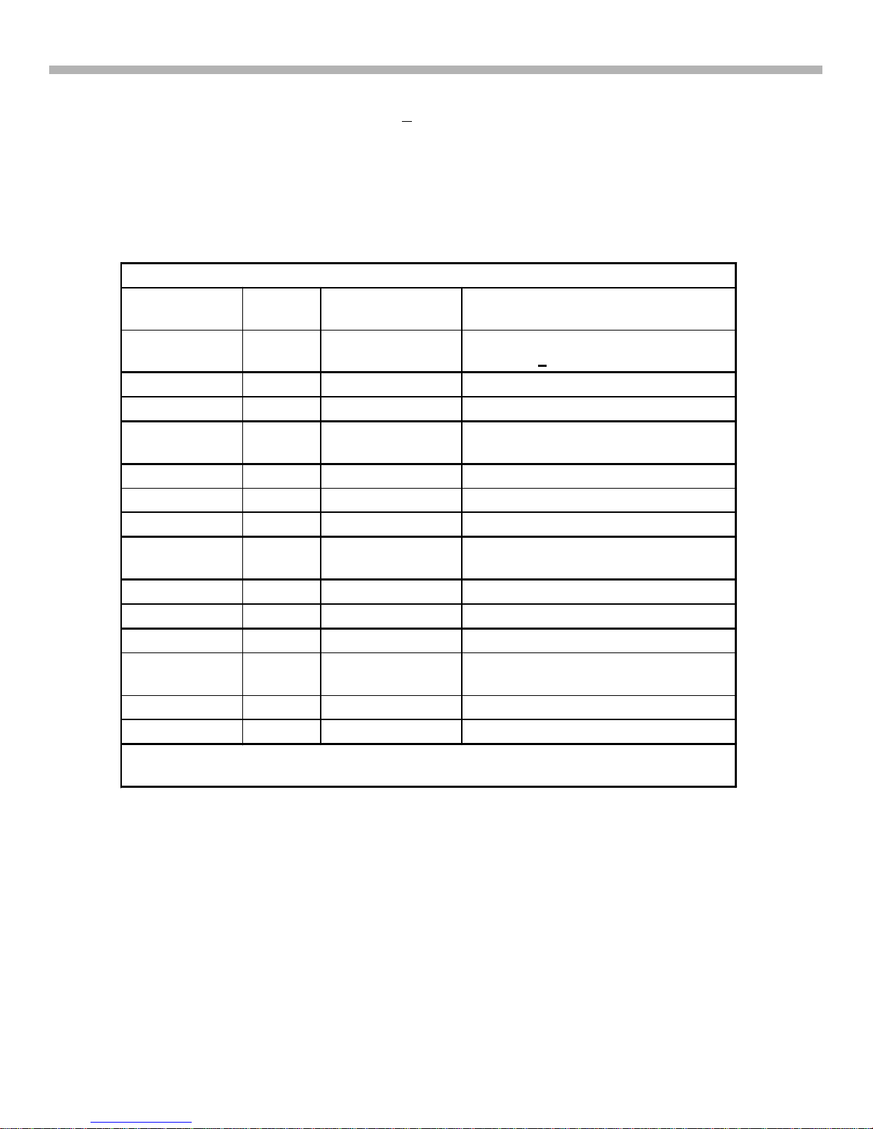
Table 1-1 shows some of the features of the Fifth Generation models.
Table 1-1 -Sony’s Popular Fifth Generation DVD Players
Model Number Intro
Year * Type Feature
DVP-NS300 2001 1 disc tray Case = Blk or Silver finish. Does not
PB –R or +RW discs.
DVP-NS315 2002 1 disc tray Black or Silver finish
DVP-NS400D 2001 1 disc tray Built in 5.1 Digital Dolby Decoder
DVP-NS415 2002 1 disc tray Silver, Built in 5.1 Digital Dolby
Decoder
DVP-NS500P 2001 1 disc tray Progressive scan
DVP-NS700P 2001 1 disc tray Progressive scan
DVP-NS715P 2002 1 disc tray Progressive scan, Silver
DVP-NS755P 2002 1 disc tray Progressive scan, SACD, Built in 5.1
Digital Dolby Decoder, Blk.
DVP-NC600 2001 5 disc Changer No thinner case like the tray units.
DVP-NC650 2001 5 disc Changer SACD
DVP-NC655P 2002 5 disc Changer Progressive scan, Blk/Silver.
DVP-CX875P 2002 300 disc changer Progressive scan, Built in 5.1 Digital
Dolby Decoder.
DVP-F25 2002 1 disc slot Case = Blk or Silver finish.
DVP-F41MS 2002 1 disc slot Memory stick for JPEG pix view
* Optical Assemblies for 2001 year Models are KHM240AAA and KHM250AAA Optical
Assemblies for 2002 year Models are KHM270AAA and KHM275AHA.

3
1. What’s New?
DualLaser OpticalBlock
Disc Playback Characteristics
All fifth generation DVD models, (except basic model DVP-NS300) can play back computer made –R or +RW
discs.
Computer made (burned) –R or +RW discs have different characteristics than machine stamped counterparts
and stamped CDs have different characteristics than DVDs. To insure full compatibility, the optical block uses
two lasers. One is optimized for CDs and the other for DVDs.
To understand how separate lasers insure playback of computer burned discs, some basics are explained here.
The reflected Laser light from the disc to the optical block contains the data. DVD discs (including DVD-R and
+RW discs) reflect best in the 650-635nM wavelength band. CD discs (including –R or +RW discs) reflect light
best at 780nM.
Figure1-2 shows thatmaximum CD-R discreflection (RF) occursat 780nM. Since –Ror +RW discshavelower
reflectivity than stamped discs (reflectivity also varies from brand to brand) output is maximized if two lasers are
used: one operating at 648nM for DVDs and another at 780nM for CDs.
Optical Pick-up
650nM 780nM Wavelength
Reflective
Intensity for
CD-R
For DVD
CD = 1.2cm
DVD=0.6cm
For CD
Lens
KHM-240
FIGURE 1-2

4
1. What’s New?
OPTICAL
ASSEMBLY
PIVOT
PIVOTS
DOWN
(LIMITED RANGE)
DISC
WHOLE
ASSEMBLY
ROTATES
FROM
HORIZONTAL
A TILT SERVO WARP
DISC COMPENSATION
B DTC WARP
DISC COMPENSATION
MOTOR
OPTICAL
ASSEMBLY
PIVOTS UP
PIVOT
DISC WHOLE
ASSEMBLY
ROTATES
FROM
HORIZONTAL
LENS
LENS
OPTICAL
ASSEMBLY
DISC ILLUSTRATES
ROTATION OF
LENS
ONLY
ASSEMBLY REMAINS
HORIZONTAL
LENS
OPTICAL
ASSEMBLY
DISC
ASSEMBLY REMAINS
HORIZONTAL
ILLUSTRATES
ROTATION OF
LENS
ONLY
LENS
GGW5 1545 4/9/03
FIGURE 1-3 - TILT SERVO (A) VS. DTC (B)
Disc Warp Correction
Because of the finer DVD pitch, the laser must be perpendicular to the disc for maximum RF output from the
optical block. Figure 1-3 illustrates the differences between old servo tilt mechanism system (A) and the new
DTC system (B) that keeps the laser beam perpendicular. In earlier generations, a tilt servo (A) adjusted the
angle of the laser platform to keep the monitored RF level at peak. This system is complex and the platform can
“bottom out”, limiting its range.

5
1. What’s New?
In fifth generation DVD players, an ingenious Dynamic Tilt Correction (DTC) system replaces the tilt servo.
Warped disc readability is achieved by tilting the lens during focus correction. The greater the focus correction,
the more the tilt.
The DTC concept and mechanics are as follows:
The DVD disc information layer is at a height determined by the spindle motor hub. This is considered as the
mechanical focus center of the lens. As the optical block moves towards the outside of the disc, disc warp
increases. At the points where the disc is angled up by warp, the focus point also moves up to compensate.
Raising the focal point causes the lens to change its angle and remain perpendicular to the disc. Conversely,
when the disc angles down (Figure 1-2 B), the lens focus goes below center and the lens tilts in the opposite
direction.
Mechanically, DTC is achieved by modifying the lens supports. The front lens supports are stronger than the
rear. See Figure 1-4. As the lens moves up, it is tilted toward the weaker support. As it moves down, the lens is
tiltedtowardthestrongersupport. Thetiltisalwaysinthedirectionofthewarpagesothelensremainsperpendicular
to the disc.
Disc Identification
The DVD player first determines what type of disc is in the tray before playing it. The player powers up one of the
lasers and begins looking for the disc’s information layer(s). The time it takes to find a layer determines how
deep the layer is inside the disc (T=0.6cm, 2T =1.2cm). Because the tracking servo is disabled at this time, the
lens will continue past the focus point of the DVC and look for a second information layer (DL disc). The disc ID
method is shown in Figure 1-5. This procedure is repeated with the second laser to insure identification of the
lower output –R and +RW discs.
Lens
Weak
Rear
Support
Stronger
Front
Support
Figure 1-4 -Lens
Retaining DTC System
FIGURE 1-4 - DTC SYSTEM

6
1. What’s New?
SuperAudioCompactDisc(SACD)
There are three types of SACDs, all played from the bottom of the disc (disc is not flipped over): See Figure
1-6.
1. Single Layer: The single high-density (HD) layer can contain 2 channel and multi-channel DSD recordings,
text (such as song tiles and lyrics), video clips and graphics.
Figure 1-5 also shows that the laser takes the least time to find a DVD disc (Figure 1-5, B, C, or D). If a second
focal point is also found, the disc is either a dual layer DVD (Figure 1-5 C) or SACD (Figure 1-5 D).
1.2 CM
CD
DISC ENTRY
INFO LAYER
Disc Type
CD
INFO LAYER
DVD/
SACD
SL 0.6 CM
SL
DISC ENTRY
1stLAYER
DVD/
SACD
DL 0.6 CM
DL
DISC ENTRY
2ndLAYER
HD LAYER
SACD-
Hybrid 0.6 CM
DISC ENTRY
CD layer
1.2 CM
DISC IDENTIFICATION 2T
T
T
T
tDL
thybrid
SACD layer CD layer
A
B
C
D
FIGURE 1-5 - DISC IDENTIFICATION

7
1. What’s New?
2. Dual layer - Two layers with twice the playing time / information as a single layer.
3. Hybrid layer – Contains one HD layer and a standard CD layer so it can be played on any standard CD player
too.
Logos
High-end products that can play one or all versions of SACD discs have at least one of three of the logos
shown in Figure 1-7.
Single layer disc
Dual layer disc
Hybrid disc
HD
layer
2 HD layers
CD layer
HD
layer
FIGURE 1-6 - SACD TYPES
Front L Center Front R
Subwoofer
Rear L Rear R
FIGURE 1-7 -SACD LOGOS

8
1. What’s New?
Video Noise Reduction
Block Noise Reduction (BNR)
BNR reduces dissimilarities (noise) at the edges of blocks (Figure 1-8).
Digital Video Enhancer (DVE)
DVE corrects the frequency response of the video signal and emphasizes picture details, see Figure 1-9. Since
DVE (Digital Video Enhancer) emphasizes BLOCK NOISE, the BNR circuit is used before the DVE .
Block Noise Reduction
The Block Noise Reduction reduces noise at vertical
rising (block) edges caused by the MPEG format.
The picture looks more smother and more natural.
Picture details, even very small once, are not effected.
FIGURE 1-8 - BLOCK NOISE REDUCTION
: Original Signal :Optimized Signal
DVE = Digital Video Enhancer
it emphasizes picture details
U
f
FIGURE 1-9 - DIGITAL VIDEO ENHANCER

9
1. What’s New?
Digital Video Enhancer & Block Noise
Reduction
Former generation (year 2000)
Might emphasize
BlockNoise!
DVE
DVEDVE
5th generation
DVE
DVEDVE
BNR
BNR
BNR
NoemphasisofBlockNoise,clearedgeand
details retained.
At first,reduce
Block Noise.
Former generation (year 2000)
Might emphasize
BlockNoise!
DVE
DVEDVE
5th generation
DVE
DVEDVE
BNR
BNR
BNR
NoemphasisofBlockNoise,clearedgeand
details retained.
At first,reduce
Block Noise.
FIGURE 1-10 - BNR AND DVE ORDER

10
2. Block Diagram
Chapter 2 - Block Diagram
Figure 2-1 shows a block diagram of fifth generation DVD players. They have the following features:
•New type of optical pickup unit. (CD or DVD laser selection not shown.)
•All analog Driver functions input to one IC (“IF Con”).
•No External RAM for Syscon IC.
•Block Noise Reduction IC.
•ARP and Servo DSP is combined in one IC.
ARP
Servo
DSP AV
Decoder
16MB
DRAM 16/ 64MB
SDRAM
FLASH or OTP
Parallel Bus
Syscon
EEPROM
RF Amp
Base Unit
DVD/CD
PD IC
Focus
Coil
Tracking
Coil
INLIMIT
Sensor
M
M
SP_Motor
Sled Motor
Focus / Tracking
Coil Drive,
Spindle / Sled/
Loading Motor
Drive
)SW
Regulator IF Con Fn Key
ND401
FLD
Loading
Motor
M
Chuck Tray
Detect
Audio
DSP Audio
D/A
Converter
BNR
CDDOUT
CDData
CDBCK/LRCK
SPDIF OUT
SPDIF
V,Y,C
SACD
DECODER
SACD
BASS
Manag.
Video Buffer
Receiver RC
FIGURE 2-1 - BLOCK DIAGRAM

11
2. Block Diagram
Table 2-1 -MB Board Main IC Functions
IC Name DVP-NS400
Ref Number DVP-NS700
Ref Number Purpose
RF Amp /
Digital
Servo
IC202 IC201 DVD/CD RF Amp,
Servo
EEPROM IC101 IC101 Servo Setting Data,
Emer. History, Hour
meter, Disc
Parameters.
Flash /
OTP IC107 IC106 &
IC107 Start up instructions /
sequence ROM
Syscon IC103 IC104 Overall Operation
(ARP) /
Servo DSP
Advanced
RF
Processor
IC302 IC302 CD/DVD Data
Processing, Servo
Control.
16M DRAM
IC303 IC301 RAM for ARP IC302
BNR IC601 IC504 Black Noise
Reduction
A/V
Decoder IC503 IC502 MPEG2, AC-3 ®
(Dolby Digital)
decoder
64M
SDRAM IC504 /
IC505 IC507 RAM for A/V Decoder
Analog
Servo IC401 IC202 Analog Servo Control
CIRCUIT BOARDS LOCATION
DVP-NS400/700
POWER BLOCK (HS15S1U)
NS500V)
(SWITCHING REGULATOR)
HS13SO3 IN -NS400
AI-23 FOR NS-400
(COMPLETELY DIFFERENT,
INCLUDES: AUDIO/VIDEO/
INTERFACE CONTROL
AV-59 NOT IN -NS400
(AUDIO/VIDEO OUT)
ER-15 IN -NS400
MB-101
(SIGNAL PROCESS, SERVO)
MB-98 IN -NS400
IF-84
(INTERFACE CONTROL)
MS-81
(LOADING)
SI-31
(REMOTE COMMANDER
RECEIVER)
NOT IN -NS400
FIGURE 2-2 - CIRCUIT BOARD

12
3. Power Supply
Chapter 3 - Power Supply
PowerSupply
The 5th Generation power supplies have the following features:
•No STANDBY circuit (Hard wire ON / OFF switch SW101).
•Simple MAIN POWER SUPPLY circuit. Q101 = switching osc. Q102 / PC101 / IC301 = feedback.
•Simple Stdby/Power ON controll.
Figure 3-1 shows a block diagram of the power supply:
Power ON Operation
The power supply circuitry before T101 (Primary) and after (Secondary) are explained. Refer to Figures 3-1 for
the block diagram. The load and additional regulators are shown in Figure 3-2.
Primary
After closing main switch SW101, oscillator circuit Q101 and the primary coils of T101starts. Regulation comes
from sampling the secondary +3.3 V at L611. The sample is sent to inverter/shunt regulator IC301, to the opto-
coupler PC101 and finally back to oscillator Q101.
EVER +3,3V from Q411 is switched via the other leg of SW101 and is applied to power ON LED D621 (RED)
drive. It is also applied to IC404/pin19 (not shown) as a P-DET signal. The output of IC404 controls the rest of
the power supply secondary circuit via the P-CONT line. EVER +3.3V powers IC404, IR remote receiver, cursor
stick and audio muting (all not shown).
L101
LINE
FILTER
AC IN
CN101
F101 POWER
SW101
L102
LINE
FILTER
EXCEPT
US. CND. TW
US. CND. TW
Q101, 102
OSC
D211
D221
L211
L221
D311 L311
T101
PC101
PHOTO
COUPLER
SHUNT
REG
IC301
D611 L611
D511 L511
D413
Q411
+3.3V
REG
SHUNT
REG
IC411 Q621, 622
LED DRIVE
Q712
POWER
CONTROL
6
7
13
12
8
11
3
2
1
P311
Q211
Q311
P611 Q611
D621 (ON/STANDBY)
EVER +3.3V
P-DET
EVER
+3.3V
P-CONT
EVER
-11V
SW
+3.3V
+5V
EVER +11V
SW
+11V
1
2
HS15S1E BOARD: AEP, UK, AUS, E, EA, HK, KP, ME, RUS, SP, CH
(SEE PAGE 4-53)
HS15S1U BOARD:US, CND
(SEE PAGE 4-61)
HS15S1J BOARD:TW
(SEE PAGE 4-57)
FIGURE 3-1 - POWER SUPPLY

13
3. Power Supply
Keep in mind that SW101 is a “hard off” switch. With the switch OFF, the unit will not turn ON with the remote.
Soft ON/OFF(standby) is controlled by the P-CONT line and Q712: it controls +11V via Q211, +5V via Q311, and
SW+3.3V via Q611.
7
Power Supply 8
AV-59 Board
AU+11V
AV-59 BOARD
IC102
VIDEO
BUFFER
IC202
AUDIO AMP
IC203
5.1CH FRONT
AUDIO AMP
IC204
5.1CH REAR
AUDIO AMP
IC205
5.1CH
CENTER/WOOFER
AUDIO AMP
IN OUT
2 3
IN OUT
1 3
-5V REG
IC101
+5V REG
IC201
3
SW-11V
6
AI+5V CN101 8
21
6
CN102
D201
MUTE V
5
EVER
+3.3V
Q201, 205
Q206
7
8
IC201
OPTICAL DIGITAL
OUT
OPTICAL
AUDIO-D/A FIGURE 3-2 - ADDITIONAL REGULATORS 4/11/033.5DVD5
Waveforms
These waveforms were taken at key areas of the power supply:
Power supply 4
Q101 / Drain / standby mode
Figure 3-3 -Scope Shot –Q101 / Drain –Stby
Mode. -304.5 Vpp Timebase: 0.1 ms Power supply 6
Q102 / GATE / standby mode
Figure 3-4-Scope Shot –Q102/Gate –
Stby Mode. 1.254 Vpp (small: ~0.6 Vpp)
Timebase: 2 ms

14
3. Power Supply
ground for scope C150
C150
Connect the scope`s ground here
Measurements on the primary side of the power supply
Measurements values on the primary side
Q101, DRAIN voltage 304,5 Vpp
Q101, GATE voltage 12,5 Vpp
Q102, BASE voltage 1,25 Vpp
All measurements use 1:10 probe in standby mode!
For safety reasons do not connect the unit to an AC out outlet!
Use an isolation transformer!
FIGURE 3-5 - HOT AC LOCATIONS

15
3. Power Supply
2. Similarly the initial communication (Hand Shaking) takes place with IC 503/ AV Decoder and IC302 /ARP.
In the event the communication with these ICs is not accomplished, System control will inform Interface
IC 404 to switch the power to standby mode.
A failure of any of the ICs (IC104, IC503 or IC302) will cause the unit to enter the Standby mode.
The Plug In communications sequence is as follows:
1. AC plug in.
2. Ever 3.3V is applied to Interface IC404 PIN 78.
3. 401 (8MHz) becomes active.
4. Pcont from IF IC404 / Pin 26 goes HIGH to Power the set.
5. After this sequence of Power ON, the following communications will take place as shown in Figure 3-7:
• Ready Pulse is output from IC404 /Pin 27 (interrupt line) to begin communications with IC103/4.
• System Controller IC103/4 sends chip select from Pin 51 to IC404 / Pin 14.
• System Controller IC103/4 sends bit clock (Pin17) and display data (Pin 26) to IC404.
6. If users command have been initiated, then these commands will be sent from IC404/Pin 16 to IC 103, 104/
Pin 25. Otherwise, IC404 will bring “Pcont” low and RST pulse /Pin 7 will be sent to IC103/4 Pin 76.
7. Set goes to Stby.
Plug-InCommunications
Figure 3-6 shows the general sequence of IC communications during Plug-in time.
1. System controller IC104 communicates with Flash Memory to retrieve the Instructions / programs.
In the event the communication with the Flash Memory is not accomplished, System control will inform
Interface IC 404 to switch the power to standby mode.
IC302
ARP
Servo
DSP
IC502
AV
Decoder
IC303
16M
DRAM
IC507
64M
SDRAM
IC106 (Or) IC107
FLASH OTP
Parallel Bus
IC104
Syscon
IC101
EEPROM
Base Unit
DVD/CD/SACD
PD ICs
)SW
Regulator
IC404
IFCon FnKey
ND401
FLD
Loading
Motor
M
Chuck Tray
Detect
IC601
Audio
DSP
IC603/4
Audio
D/A
Converter
Power on
1
2
3
DVP-NS500/700:
IC-Communications
at POWER ON
FIGURE 3-6

16
3. Power Supply
Serial Data Communications after Power ON
The serial data bus connects several ICs and consists of two or three lines. Serial data is transmitted from one
IC to another on a unidirectional line (arrows shown in one direction). This data is accompanied by a clock signal
for a total of two lines in a unidirectional serial communication. The interface control IC404 and syscon IC104
communicate bidirectionally (arrows shown in two directions). Three lines are necessary when bi-directional
transmissions are used. There is a data line for each direction. The additional clock signal makes a total of three
lines for a bi-directional serial bus. The clock signal usually comes from the controlling micro, which in this case
is syscon IC104.
IC104 communications with interface IC404, EEProm IC101, SACD decoder IC806, SACD bass management
IC807 and DSP IC601 are bi-directional.
Syscon communications to the Digital to Analog Converters (DAC) IC603, IC604 are uni-directional.
FIGURE 3-7 - PLUG IN SEQUENCE
16
15
17
14
27
SC0
SO0
XIFCS
XIFBSY
25
26
17
51
20
XFRST 776
IC404
IFCON IC103/4
SYSCON
INT4
Display Update
SI0
Serial Clock
Chip Select
User Commands
Interrupt
Stop
1
2
3
4
5
6
Start IFCONàSYSCON
INT SYSCONàIFCON
Clock/Data IFCONàSYSCON
XFRST End
Red LED Green LED Red LED
Plug-In Std-By
1.3 Seconds
3.3v
78 26
Ever +3,3 V Pcont

17
3. Power Supply
Parallel Data Communications after Power ON
See Figure 3-8
The parallel data bus consists of address lines, data lines, a WE (write enable) and a RE (read enable) line, and
a clock line. The parallel bus is contoleed by system control IC202.
FIGURE 3-8 - COMMUNICATIONS BLOCK

18
4. Testing and Test Point Access
Chapter 4 - Testing and Test Point Access
This section is divided into two parts: 1) Test point access; and 2) testing the RF and servo sections using the
service / test mode.
The signals are generated by the optical assembly’s photo detectors as listed in Table 4-1.
Table 4-1 -Photo Detector and Their Manufactured Signals
Photo
Detector Signals Purpose
A-DTE (DVD only),
FE, PI, Mirror,
RF (eye
pattern)
TE = DVD tracking error.
FE = Focus error.
PI = “Pull In” is the analog sum of A-D detectors. Disc ID
the disc and MIRR.
MIRR counts tracks and ID disc.
RF = Sum of A-D detectors.
E & F TE + and TZC CD tracking error, track counting
G & H TE –and TZC CD tracking error, track counting
Access - RF Output
The RF test point is easily accessed. See Figures 4-1 through 4-3. Figure 4-4 shows the RF waveforms.
RF measurements locations I
1 RF in/PIN2
FIGURE 4-1 - IC201 RF TEST POINT
Other manuals for DVP-NS300
6
This manual suits for next models
13
Table of contents
Other Sony DVD Player manuals

Sony
Sony DVP-K80P User manual

Sony
Sony DVP-NS75H User manual

Sony
Sony DVP-CX875P User manual

Sony
Sony DVP-SR150 User manual

Sony
Sony DVP-NS32 User manual

Sony
Sony DVP-CX777ES Instruction Manual

Sony
Sony DVP-NS425P User manual

Sony
Sony DVP-K880P User manual

Sony
Sony DVP-F250 User manual

Sony
Sony DVP-NS300 User manual

Sony
Sony DVP-SR500H User manual

Sony
Sony DVP-SR760H User manual

Sony
Sony DVP-SR101P User manual

Sony
Sony HCD-WZ8D User manual

Sony
Sony DVP-NS500V Instructions and recipes

Sony
Sony DVP-SR400P User manual

Sony
Sony DVP-NC650V User manual

Sony
Sony DVP-NS715P User manual

Sony
Sony DVP-LS785V User manual

Sony
Sony DVP-PQ2 User manual