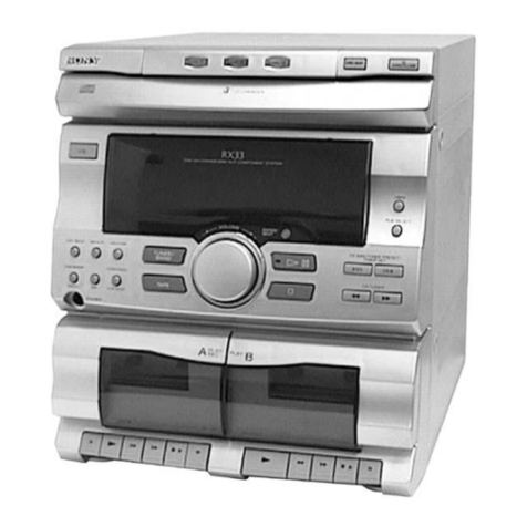
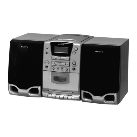
Sony HCD-V515 User manual

MICROFILM
SERVICE MANUAL
MINI Hi-Fi COMPONENT SYSTEM
E Model
Chinese Model
SPECIFICATIONS
HCD-V515
Dolby noise reduction manufactured under license
from Dolby Laboratories Licensing Corporation.
“DOLBY” and the double-D symbol aare trade-
marks of Dolby Laboratories Licensing Corporation.
HCD-V515 is the Amplifier, Video CD
player, Tape Deck and Tuner section in
MHC-V515.
– Continued on next page –
• HCD-V515 is almost same as HCD-V717.
This manual contains only the points which differ
from HCD-V717.
Please refer to HCD-V717 service manual (9-922-879-∏)
previously issued for other information.
w
w
w
.
x
i
a
o
y
u
1
6
3
.
c
o
m
Q
Q
3
7
6
3
1
5
1
5
0
9
9
2
8
9
4
2
9
8
T
E
L
1
3
9
4
2
2
9
6
5
1
3
9
9
2
8
9
4
2
9
8
0
5
1
5
1
3
6
7
3
Q
Q
TEL 13942296513 QQ 376315150 892498299
http://www.xiaoyu163.com
– 3 –
TABLE OF CONTENTS
1. SERVICING NOTES ............................................... 3
2. GENERAL
Location of Controls ....................................................... 5
Setting the Time .............................................................. 6
3. DIAGRAMS
3-1. Note for Printed Wiring Boards and
Schematic Diagrams ....................................................... 8
3-2. Printed Wiring Board – MAIN Section – ...................... 9
3-3. Schematic Diagram – MAIN Section (1/4) –............... 11
3-4. Schematic Diagram – MAIN Section (2/4) –................ 13
3-5. Schematic Diagram – MAIN Section (3/4) –................ 15
3-6. Schematic Diagram – MAIN Section (4/4) –................ 17
3-7. Printed Wiring Board – PANEL Section – .................... 19
3-8. Schematic Diagram – PANEL Section – ....................... 21
3-9. Printed Wiring Board – POWER AMP Section – ......... 24
3-10. Schematic Diagram – POWER AMP Section –............ 25
3-11. Printed Wiring Board
– TRANSFORMER Section – ........................................ 27
3-12. Schematic Diagram
– TRANSFORMER Section – ........................................ 28
4. EXPLODED VIEWS................................................ 29
5. ELECTRICAL PARTS LIST ............................... 33
SECTION 1
SERVICING NOTES
The laser diode in the optical pick-up block may suffer electro-
static break-down because of the potential difference generated
by the charged electrostatic load, etc. on clothing and the human
body.
During repair, pay attention to electrostatic break-down and also
use the procedure in the printed matter which is included in the
repair parts.
The flexible board is easily damaged and should be handled with
care.
NOTES ON LASER DIODE EMISSION CHECK
The laser beam on this model is concentrated so as to be focused
on the disc reflective surface by the objective lens in the optical
pick-up block. Therefore, when checking the laser diode emis-
sion, observe from more than 30 cm away from the objective lens.
Notes on chip component replacement
• Never reuse a disconnected chip component.
• Notice that the minus side of a tantalum capacitor may be dam-
aged by heat.
Flexible Circuit Board Repairing
• Keep the temperature of the soldering iron around 270 ˚C dur-
ing repairing.
• Do not touch the soldering iron on the same conductor of the
circuit board (within 3 times).
• Be careful not to apply force on the conductor when soldering
or unsoldering.
NOTES ON HANDLING THE OPTICAL PICK-UP
BLOCK OR BASE UNIT
CAUTION
Use of controls or adjustments or performance of procedures
other than those specified herein may result in hazardous ra-
diation exposure.
This appliance is classified as a CLASS 1 LASER product.
The CLASS 1 LASER PRODUCT MARKING is located on
the rear exterior.
Laser component in this product is capable of emitting radiation
exceeding the limit for Class 1.
The following caution label is located inside the unit.
w
w
w
.
x
i
a
o
y
u
1
6
3
.
c
o
m
Q
Q
3
7
6
3
1
5
1
5
0
9
9
2
8
9
4
2
9
8
T
E
L
1
3
9
4
2
2
9
6
5
1
3
9
9
2
8
9
4
2
9
8
0
5
1
5
1
3
6
7
3
Q
Q
TEL 13942296513 QQ 376315150 892498299
http://www.xiaoyu163.com
– 4 –
MODEL IDENTIFICATION
– Back Panel –
PART No.
MODEL PART No.
Malaysia and Singapore models 4-999-906-0π
Saudi Arabia model 4-999-906-1π
Chinese model 4-999-906-2π
Hong Kong model 4-999-906-3π
Taiwan model 4-999-906-4π
Indonesia model 4-999-906-5π
Thai model 4-999-906-9π
SAFETY-RELATED COMPONENT WARNING!!
COMPONENTS IDENTIFIED BY MARK !OR DOTTED
LINE WITH MARK !ON THE SCHEMATIC DIAGRAMS
AND IN THE PARTS LIST ARE CRITICAL TO SAFE
OPERATION. REPLACE THESE COMPONENTS WITH
SONY PARTS WHOSE PART NUMBERS APPEAR AS
SHOWN IN THIS MANUAL OR IN SUPPLEMENTS PUB-
LISHED BY SONY.
IC502 OF VIDEO BOARD
IC502 of the VIDEO board consists of the former type and new
type. The following table shows the differences between the two
types.
Only spare parts for the new type IC502 are supplied.
Units using the former IC502 will not function when replaced with
the new type without performing the following procedure.
Consequently, replace IC502 of units using the former type ac-
cording to the following procedure.
Table of Differences
Replacing Procedure
1. Remove IC402.
2. Solder JW421 and JW422, or short-circuit with a lead wire,
etc.
3. Replace IC502 with a new one.
How to Differentiate
[VIDEO board] (Side A)
FORMER TYPE NEW TYPE
C407, 408 MOUNT NO MOUNT
IC502 M30620MC-302FP M30620MC-305FP
JW421, JW422 NO MOUNT MOUNT
IC402 MOUNT NO MOUNT
R413, 421, 422 MOUNT NO MOUNT
X401 MOUNT NO MOUNT
Those with IC402 : FORMER TYPE
Those without IC402: NEWTYPE
w
w
w
.
x
i
a
o
y
u
1
6
3
.
c
o
m
Q
Q
3
7
6
3
1
5
1
5
0
9
9
2
8
9
4
2
9
8
T
E
L
1
3
9
4
2
2
9
6
5
1
3
9
9
2
8
9
4
2
9
8
0
5
1
5
1
3
6
7
3
Q
Q
TEL 13942296513 QQ 376315150 892498299
http://www.xiaoyu163.com

– 5 –
SECTION 2
GENERAL
LOCATION OF CONTROLS
• Front view
1 2
!§
!∞
@º
@¡
@™
@£
@¢
@∞
5
6
7
8
9
!º
!¡
!™
!£
!¢
#¢
#∞
#•
#ª
$º
@ª
#º
#¡
#™
#£
$¡ $™ $£ $¢ $∞ $§ $¶
1I /u(Power) button
2DISC 1 to 3 buttons and indicators
3DISC SKIP/EX-CHANGE button
46(CD) button
5CD disc tray
6CD ^button and indicator
7TUNER, BAND button
8rREC button and indicator
9PPAUSE button and indicator
!º HI-DUB button
!¡ CD SYNC button
!™ FILE SELECT button
!£ SURROUND button
!¢ KARAOKE PON/MPX button
!∞ DECK B 9and (buttons and indicators
!§ DECK A 9and (buttons and indicators
!¶ FUNCTION button
!• ECHO LEVEL knob
!ª MIC LEVEL knob
@º MIC1 jack
@¡ MIC2 jack
@™ DISPLAY/DEMO button
@£ CLOCK/TIMER SET button
@¢ TIMER SELECT button
@∞ pbutton
!ª
#¶
3 4
!•
!¶
@§ Fluorescent indicator tube
@¶ ENTER/NEXT button and indicator
@• ACTIVE, SELECT, RETURN, PREV, NEXT button
@ª VIDEO CD, PBC, PBC OFF indicators
#º GROOVE button and indicator
#¡ VOLUME konb
#™ PHONES jack
#£ DBFB button
#¢ Remote sensor
#∞ CD LOOP button
#§ CD NON-STOP button and indicator
#¶ CD FLASH button
#• EDIT, DIRECTION button
#ª PLAY MODE, DOLBY NR button
$º REPEAT button
$¡ §button (deck A)
$™ Tape deck A
$£ –, 0button and indicator
$¢ JOG dial
$∞ +, )button and indicator
$§ Tape deck B
$¶ §button (deck B)
@§ @¶ @•
#§
w
w
w
.
x
i
a
o
y
u
1
6
3
.
c
o
m
Q
Q
3
7
6
3
1
5
1
5
0
9
9
2
8
9
4
2
9
8
T
E
L
1
3
9
4
2
2
9
6
5
1
3
9
9
2
8
9
4
2
9
8
0
5
1
5
1
3
6
7
3
Q
Q
TEL 13942296513 QQ 376315150 892498299
http://www.xiaoyu163.com
– 6 –
1
8
74
• Rear view
2 3
!º
9
5
6
1S VIDEO OUT jack
2SYSTEM SELECT switch
3VIDEO OUT jack
4FM antenna terminal
5AM antenna terminal
6VOLTAGE SELECTOR switch
(EXCEPT Thai and Chinese models)
7CD DIGITAL OUT, OPTICAL connector
8MD/VIDEO (AUDIO), IN/OUT jacks
9SUPER WOOFER jack
!º SPEAKER terminals
w
w
w
.
x
i
a
o
y
u
1
6
3
.
c
o
m
Q
Q
3
7
6
3
1
5
1
5
0
9
9
2
8
9
4
2
9
8
T
E
L
1
3
9
4
2
2
9
6
5
1
3
9
9
2
8
9
4
2
9
8
0
5
1
5
1
3
6
7
3
Q
Q
TEL 13942296513 QQ 376315150 892498299
http://www.xiaoyu163.com
– 8 –
SECTION 3
DIAGRAMS
3-1. NOTE FOR PRINTED WIRING BOARDS AND SCHEMATIC DIAGRAMS
Note on Schematic Diagrams:
• All capacitors are in µF unless otherwise noted. pF: µµF
50 WV or less are not indicated except for electrolytics
and tantalums.
• All resistors are in Ωand 1/4W or less unless otherwise
specified.
•¢: internal component.
•2: nonflammable resistor.
•5: fusible resistor.
•C: panel designation.
Note on Printed Wiring Boards:
•X: parts extracted from the component side.
•®:Through hole.
•b: Pattern from the side which enables seeing.
(The other layers' patterns are not indicated.)
•U: B+ Line.
•V: B– Line.
• Voltages are taken with aVOM (Input impedance10 MΩ).
Voltage variations may be noted due to normal produc-
tion tolerances.
• Waveforms are taken with a oscilloscope.
Voltage variations may be noted due to normal produc-
tion tolerances.
• Circled numbers refer to waveforms.
• Signal path.
F:TUNER (FM/AM)
E: PLAYBACK (DECK A)
d: PLAYBACK (DECK B)
G: RECORD
J: CD PLAY (AUDIO)
L: CD PLAY (VIDEO)
c: DIGITAL OUT
N: MIC INPUT
• Abbreviation
CH : Chinese model.
TH :Thai model.
Caution:
Pattern face side: Partsonthepattern facesideseenfrom
(Side B) the pattern face are indicated.
Parts face side: Parts on the parts face side seen from
(Side A) the parts face are indicated.
Ref. No. Location
Ref.No. Location
• Semiconductor Location
D141 G-9
D333 E-2
D334 F-2
D401 G-10
D501 E-5
D502 E-5
D503 E-5
D504 E-5
D505 E-6
D506 E-6
D507 F-3
D508 F-2
D901 I-6
D902 I-5
D903 I-6
D904 I-6
D905 G-6
D906 G-7
D907 H-4
D908 H-4
D909 I-5
D910 I-4
D911 I-4
D912 I-4
D913 G-3
D914 G-5
D915 I-3
D-917 F-7
D-918 G-4
IC101 D-9
IC102 F-10
IC191 D-11
IC301 B-2
IC381 A-11
IC501 D-4
IC502 E-6
IC901 G-5
IC902 G-3
IC903 H-3
IC904 F-4
Q111 F-9
Q112 F-9
Q113 H-8
Q161 E-8
Q162 D-8
Q163 H-8
Q191 D-11
Q331 C-2
Q332 D-2
Q333 C-2
Q334 D-2
Q335 C-1
Q336 E-2
Q337 E-2
Q338 F-2
Q339 F-2
Q340 E-2
Q341 E-2
Q342 E-2
Q343 E-2
Q431 G-9
Q432 H-8
Q433 H-9
Q434 H-8
Q435 H-8
Q436 G-8
Q437 G-8
Q501 E-7
Q571 E-6
Q572 E-6
Q575 F-8
Q901 F-6
Q902 G-6
Q903 H-6
Q905 F-6
Q906 G-6
Q907 G-4
Q908 G-5
Q909 H-4
Q910 I-4
Q911 F-3
Q912 F-3
Q913 G-6
Q914 F-7
Q951 G-7
Q952 G-7
The components identified by mark !or dotted
line with mark !are critical for safety.
Replaceonlywithpartnumberspecified.
w
w
w
.
x
i
a
o
y
u
1
6
3
.
c
o
m
Q
Q
3
7
6
3
1
5
1
5
0
9
9
2
8
9
4
2
9
8
T
E
L
1
3
9
4
2
2
9
6
5
1
3
9
9
2
8
9
4
2
9
8
0
5
1
5
1
3
6
7
3
Q
Q
TEL 13942296513 QQ 376315150 892498299
http://www.xiaoyu163.com
HCD-V515
– 9 – – 10 –
3-2. PRINTED WIRING BOARD – MAIN Section –
(CH)
(EXCEPT CH)
(EXCEPT CH)
13
1
13
JW239
12
(TH, CH)
EXCEPT
TH,CH
(
(
JW042
JW396
JW395
JW394
JW509
C915
R919
R918
D918
B
C
E
Q912
R917
C923
R916
Q911
BCEIC904
D333
D508
D334
D917
JW503
VIDEO BOARD
CN503
R395
C922
C916
POWER ANP BOARD
11
IC382
1
7
814
CN801
SPEAKER
IMPEDANCE
USE 6-16Ω
HCD-V515 MAIN
(Page 24)(Page 27)
(Page 19)
(See page 41 on
HCD-V717
service manual)
(See page 41 on
HCD-V717
service manual)
(See page 36 on
HCD-V717
service manual)
(See page
46 on HCD-
V717 service
manual)
(See page
50 on HCD-
V717 service
manual)
(See page 67 on
HCD-V717
service manual)
w
w
w
.
x
i
a
o
y
u
1
6
3
.
c
o
m
Q
Q
3
7
6
3
1
5
1
5
0
9
9
2
8
9
4
2
9
8
T
E
L
1
3
9
4
2
2
9
6
5
1
3
9
9
2
8
9
4
2
9
8
0
5
1
5
1
3
6
7
3
Q
Q
TEL 13942296513 QQ 376315150 892498299
http://www.xiaoyu163.com
HCD-V515
– 11 – – 12 –
• Voltages and waveforms are dc with respect to ground
under no-signal (detuned) conditions.
no mark : FM
( ) : CD
3-3. SCHEMATIC DIAGRAM – MAIN Section (1/4) –
(See Page 37
on HCD-V717
Service manual)
(See Page 44
on HCD-V717
Service manual)
(See Page 44
on HCD-V717
Service manual)
(Page 15)
(Page 13)
(Page 17)
w
w
w
.
x
i
a
o
y
u
1
6
3
.
c
o
m
Q
Q
3
7
6
3
1
5
1
5
0
9
9
2
8
9
4
2
9
8
T
E
L
1
3
9
4
2
2
9
6
5
1
3
9
9
2
8
9
4
2
9
8
0
5
1
5
1
3
6
7
3
Q
Q
TEL 13942296513 QQ 376315150 892498299
http://www.xiaoyu163.com
HCD-V515
– 13 – – 14 –
3-4. SCHEMATIC DIAGRAM – MAIN Section (2/4) –
• Voltages and waveforms are dc with respect to ground
under no-signal (detuned) conditions.
no mark : FM
(Page 26)
(Page 12)
(Page 17)
(See Page 67
on HCD-V717
Service manual)
The components identified by mark !or dotted
line with mark !are critical for safety.
Replaceonlywithpartnumber specified.
w
w
w
.
x
i
a
o
y
u
1
6
3
.
c
o
m
Q
Q
3
7
6
3
1
5
1
5
0
9
9
2
8
9
4
2
9
8
T
E
L
1
3
9
4
2
2
9
6
5
1
3
9
9
2
8
9
4
2
9
8
0
5
1
5
1
3
6
7
3
Q
Q
TEL 13942296513 QQ 376315150 892498299
http://www.xiaoyu163.com

HCD-V515
– 15 – – 16 –
3-5. SCHEMATIC DIAGRAM – MAIN Section (3/4) –
• Voltages and waveforms are dc with respect to ground
under no-signal (detuned) conditions.
no mark : FM {} : PB (DECK A)
( ) : CD [ ] : PB (DECK B)
< > : REC
(See Page 50
on HCD-V717
Service manual)
(See Page 48
on HCD-V717
Service manual) (Page 17)
(Page 11)
w
w
w
.
x
i
a
o
y
u
1
6
3
.
c
o
m
Q
Q
3
7
6
3
1
5
1
5
0
9
9
2
8
9
4
2
9
8
T
E
L
1
3
9
4
2
2
9
6
5
1
3
9
9
2
8
9
4
2
9
8
0
5
1
5
1
3
6
7
3
Q
Q
TEL 13942296513 QQ 376315150 892498299
http://www.xiaoyu163.com

HCD-V515
– 17 – – 18 –
• Voltages and waveforms are dc with respect to ground
under no-signal (detuned) conditions.
no mark : FM {} : PB (DECK A)
( ) : CD [ ] : PB (DECK B)
< > : REC
3-6. SCHEMATIC DIAGRAM – MAIN Section (4/4) –
(Page 12)
(Page 13)
(Page 16)
(Page 22)
(Page 28)
w
w
w
.
x
i
a
o
y
u
1
6
3
.
c
o
m
Q
Q
3
7
6
3
1
5
1
5
0
9
9
2
8
9
4
2
9
8
T
E
L
1
3
9
4
2
2
9
6
5
1
3
9
9
2
8
9
4
2
9
8
0
5
1
5
1
3
6
7
3
Q
Q
TEL 13942296513 QQ 376315150 892498299
http://www.xiaoyu163.com
HCD-V515
– 19 – – 20 –
3-7. PRINTED WIRING BOARD – PANEL Section –
Ref. No. Location
Ref. No. Location
• Semiconductor Location
D602 D-7
D610 D-5
D612 E-4
D613 D-6
D614 F-6
D615 F-6
D616 E-9
D617 E-4
D618 E-7
D621 C-4
D622 C-5
D623 C-6
D624 C-7
D625 C-8
D626 B-3
D627 B-3
D628 A-3
D651 C-1
D652 D-1
D751 E-11
D752 E-12
D753 E-12
IC601 B-6
IC602 A-9
IC603 B-8
IC750 C-13
IC751 D-12
Q601 D-6
Q602 D-7
Q603 D-7
Q604 D-5
Q607 B-3
Q608 B-3
Q609 C-6
Q610 C-9
Q611 A-3
Q618 E-1
Q620 A-7
Q621 A-6
Ref. No. Location
1-670-068-
11
J750, 751
R751
R750
ECHO
LEVEL
MIC
LEVEL
MIC 1
MIC 2
C750
R769
C751
R768
CD FLASH CD NON-STOP CD LOOP
C636
Q611
R680
R681
R682
NEXT
S630
PREV
S629
RETURN
S628
SELECT
S627
S626
ACTIVE
R645
R646
R648
R644
R647
VIDEO CD
PBC
PBC OFF
J751
J750
11
FILE SELECT
D628
D626
D627
TUNER
BAND
SURROUND KARAOKE PON/MPX
ENTER/NEXT
GROOVE
DJ MIX
(Page 9)
(See page 66 on
HCD-V717
service manual)
w
w
w
.
x
i
a
o
y
u
1
6
3
.
c
o
m
Q
Q
3
7
6
3
1
5
1
5
0
9
9
2
8
9
4
2
9
8
T
E
L
1
3
9
4
2
2
9
6
5
1
3
9
9
2
8
9
4
2
9
8
0
5
1
5
1
3
6
7
3
Q
Q
TEL 13942296513 QQ 376315150 892498299
http://www.xiaoyu163.com
HCD-V515
– 21 – – 22 –
3-8. SCHEMATIC DIAGRAM – PANEL Section –
• Voltages and waveforms are dc with respect to ground
under no-signal (detuned) conditions.
no mark : FM
(See Page 65
on HCD-V717
Service manual)
(Page 18)
w
w
w
.
x
i
a
o
y
u
1
6
3
.
c
o
m
Q
Q
3
7
6
3
1
5
1
5
0
9
9
2
8
9
4
2
9
8
T
E
L
1
3
9
4
2
2
9
6
5
1
3
9
9
2
8
9
4
2
9
8
0
5
1
5
1
3
6
7
3
Q
Q
TEL 13942296513 QQ 376315150 892498299
http://www.xiaoyu163.com
HCD-V515
– 24 –
3-9. PRINTED WIRING BOARD – POWER AMP Section –
• Semiconductor
Location
Ref. No. Location
D800 D-1
D801 F-2
D841 F-2
D842 F-2
D843 C-2
D851 C-2
IC801 E-3
Q801 F-2
Q851 C-2
HCD-V515
13
CH
11
(Page 27)
(Page 10)
w
w
w
.
x
i
a
o
y
u
1
6
3
.
c
o
m
Q
Q
3
7
6
3
1
5
1
5
0
9
9
2
8
9
4
2
9
8
T
E
L
1
3
9
4
2
2
9
6
5
1
3
9
9
2
8
9
4
2
9
8
0
5
1
5
1
3
6
7
3
Q
Q
TEL 13942296513 QQ 376315150 892498299
http://www.xiaoyu163.com
HCD-V515
– 25 – – 26 –
3-10. SCHEMATIC DIAGRAM – POWER AMP Section –
• Voltages and waveforms are dc with respect to ground
under no-signal (detuned) conditions.
no mark : FM
The components identified by mark !or dotted
line with mark !are critical for safety.
Replaceonlywithpartnumberspecified.
(Page 28)
(Page 13)
w
w
w
.
x
i
a
o
y
u
1
6
3
.
c
o
m
Q
Q
3
7
6
3
1
5
1
5
0
9
9
2
8
9
4
2
9
8
T
E
L
1
3
9
4
2
2
9
6
5
1
3
9
9
2
8
9
4
2
9
8
0
5
1
5
1
3
6
7
3
Q
Q
TEL 13942296513 QQ 376315150 892498299
http://www.xiaoyu163.com
HCD-V515
11
1-670-069-
(EXCEPT TH, CH)
(TH, CH)
(EXCEPT TH, CH)
11
– 27 – – 28 –
3-11. PRINTED WIRING BOARD – TRANSFORMER Section –
3-12. SCHEMATIC DIAGRAM –TRANSFORMER Section –
The components identified by mark !or dotted
line with mark !are critical for safety.
Replaceonlywithpart numberspecified.
(Page 24)(Page 9)
(Page 26)
(Page 18)
w
w
w
.
x
i
a
o
y
u
1
6
3
.
c
o
m
Q
Q
3
7
6
3
1
5
1
5
0
9
9
2
8
9
4
2
9
8
T
E
L
1
3
9
4
2
2
9
6
5
1
3
9
9
2
8
9
4
2
9
8
0
5
1
5
1
3
6
7
3
Q
Q
TEL 13942296513 QQ 376315150 892498299
http://www.xiaoyu163.com
– 29 –
SECTION 4
EXPLODED VIEWS
The components identified by
mark !or dotted line with mark
!are critical for safety.
Replace only with part number
specified.
• Items marked “*” are not stocked since they
are seldom required for routine service. Some
delay should be anticipated when ordering
these items.
• The mechanical parts with no reference num-
ber in the exploded views are not supplied.
• Hardware (# mark) list is given in the last of
the electrical parts list.
NOTE:
• -XX and -X mean standardized parts, so they
may have some difference from the original
one.
• Color Indication of Appearance Parts
Example:
KNOB, BALANCE (WHITE) . . . (RED)
↑↑
Parts Color Cabinet's Color
• Abbreviation
CH : Chinese MY : Malaysia
EA : Saudi Arabia SP : Singapore
HK : Hong Kong TH : Thai
IA : Indonesia TW : Taiwan
Ref. No. Part No. Description Remark Ref. No. Part No. Description Remark
(1) CASE SECTION
1 1-773-025-11 WIRE (FLAT TYPE) (15 CORE) (33cm)
2 X-4949-350-1 LID (R) ASSY, CASSETTE
3 4-991-781-01 EMBLEM (VCD)
4 X-4949-349-1 LID (L) ASSY, CASSETTE
5 4-900-739-01 PANEL, LOADING
6 1-769-984-11 WIRE (FLAT TYPE) (13 CORE) (23cm)
7 3-363-099-11 SCREW (CASE 3 TP2) (3X8)
8 3-363-099-71 SCREW (CASE 3 TP2) (3X12)
*9 4-996-728-01 CASE (EXCEPT IA)
*9 4-996-728-21 CASE (IA)
10 1-773-048-11 WIRE (FLAT TYPE) (17 CORE)
9
8
8
7
10 1
7
5
3
4
2
6
#1
#5
#2
#2
#3
#3
Front panel
not supplied TCM-230AWR1
TCM-230PWR1
w
w
w
.
x
i
a
o
y
u
1
6
3
.
c
o
m
Q
Q
3
7
6
3
1
5
1
5
0
9
9
2
8
9
4
2
9
8
T
E
L
1
3
9
4
2
2
9
6
5
1
3
9
9
2
8
9
4
2
9
8
0
5
1
5
1
3
6
7
3
Q
Q
TEL 13942296513 QQ 376315150 892498299
http://www.xiaoyu163.com
– 30 –
Ref. No. Part No. Description Remark Ref. No. Part No. Description Remark
(2) FRONT PANEL SECTION
51 X-4949-980-1 PANEL ASSY, FRONT
52 4-930-336-61 FOOT (FELT)
53 4-962-708-11 EMBLEM (4-A), SONY
54 4-995-081-01 LATCH, DC
55 4-996-722-01 KNOB (VOL)
56 4-996-721-01 KNOB (JOG-U4)
*57 4-996-716-01 HOLDER (CDM)
58 4-951-620-01 SCREW (2.6X8), +BVTP
59 4-986-893-51 KNOB (MICROPHONE)
*60 1-670-067-11 CD-SW BOARD
*61 A-4414-008-A PANEL BOARD, COMPLETE
*62 1-670-070-11 HP BOARD
*63 3-973-975-21 DAMPER, OIL
64 4-996-704-01 BUTTON (POWER) (1/u)
65 4-997-070-01 BUTTON (OPEN/CLOSE) (6)
66 X-4949-348-1 BUTTON (REC) ASSY
(rREC, PPAUSE, HI-DUB, CD SYNC)
67 4-996-733-01 SPRING (B DECK)
68 4-996-732-01 SPRING (A DECK)
54
54
56
55
51
65
64
66
52 63
#7
#7
not supplied
68
67
63
58
58
58
58
58
58
60
58
59
58
57
53
58
58
62
61
(including
r
A,
r
B)
57
not supplied
supplied with J421
#2
supplied with
J750, 751
r
A
r
B
not supplied
supplied
with S601
supplied with
S602
w
w
w
.
x
i
a
o
y
u
1
6
3
.
c
o
m
Q
Q
3
7
6
3
1
5
1
5
0
9
9
2
8
9
4
2
9
8
T
E
L
1
3
9
4
2
2
9
6
5
1
3
9
9
2
8
9
4
2
9
8
0
5
1
5
1
3
6
7
3
Q
Q
TEL 13942296513 QQ 376315150 892498299
http://www.xiaoyu163.com
– 31 – – 32 –
(3) CHASSIS SECTION Ref. No. Part No. Description Remark Ref. No. Part No. Description Remark
The components identified by mark !or dotted
line with mark !are critical for safety.
Replace only with part number specified.
107
117
116
105
106
104
#2
CDM38L-5BD24AL
#5
#2
T11
#2
not supplied
not supplied
#4
#2 #2 #2
#2
A
A
#2
#1
IA, TH
EA, MY, SP, HK, TW
HK
EA, MY, SP,
TW
IA
103
101 102
108
109
112
111
110
115
115
114
CH
114
115
114
#2
#2
#2
#2
not supplied
not supplied
113
HK
*101 A-4414-003-A POWER AMP BOARD, COMPLETE
(EXCEPT CH)
*101 A-4414-014-A POWER AMP BOARD, COMPLETE (CH)
*102 3-703-244-00 BUSHING (2104), CORD (EXCEPT TH, IA)
102 3-703-571-11 BUSHING (S) (4516), CORD (TH)
102 4-966-266-01 BUSHING (S) (FBS002), CORD (IA)
*103 1-670-069-11 TRANSFORMER BOARD
*104 4-996-736-01 DUCT (A)
*105 4-996-701-01 DUCT (B)
106 1-775-212-11 WIRE (FLAT TYPE) (23 CORE)
*107 4-999-906-01 PANEL, BACK (SP, MY)
*107 4-999-906-11 PANEL, BACK (EA)
*107 4-999-906-21 PANEL, BACK (CH)
*107 4-999-906-31 PANEL, BACK (HK)
*107 4-999-906-41 PANEL, BACK (TW)
*107 4-999-906-51 PANEL, BACK (IA)
*107 4-999-906-61 PANEL, BACK (TH)
108 1-773-008-11 WIRE (FLAT TYPE) (15 CORE) (14cm)
109 1-233-545-11 ENCAPSULATED COMPONENT (TH)
109 1-693-381-11 TUNER, FM/AM (CH)
109 1-693-421-11 TUNER (FM/AM) (EXCEPT TH, CH)
*110 A-4414-000-A MAIN BOARD, COMPLETE (EXCEPT TH, CH)
*110 A-4414-011-A MAIN BOARD, COMPLETE (CH)
*110 A-4414-494-A MAIN BOARD, COMPLETE (TH)
111 4-965-822-01 FOOT
*112 4-988-533-01 HOLDER, PWB
113 4-956-370-12 BAND, PLUG FIXED (HK)
!114 1-575-651-11 CORD, POWER (EA, HK, SP, MY, TW)
!114 1-575-653-11 CORD, POWER (IA, TH)
!114 1-782-464-21 CORD, POWER (CH)
!115 1-569-007-11 ADAPTOR, CONVERSION 2P (IA)
!115 1-569-008-21 ADAPTOR, CONVERSION 2P (EA, SP, MY, TW)
!115 1-770-019-11 ADAPTOR, CONVERSION PLUG 3P (HK)
116 1-751-688-11 WIRE (FLAT TYPE) (13 CORE) (17cm)
*117 A-4414-186-A VIDEO BOARD, COMPLETE (EXCEPT CH)
*117 A-4724-279-A VIDEO BOARD, COMPLETE (CH)
!T11 1-431-830-11 TRANSFORMER, POWER
w
w
w
.
x
i
a
o
y
u
1
6
3
.
c
o
m
Q
Q
3
7
6
3
1
5
1
5
0
9
9
2
8
9
4
2
9
8
T
E
L
1
3
9
4
2
2
9
6
5
1
3
9
9
2
8
9
4
2
9
8
0
5
1
5
1
3
6
7
3
Q
Q
TEL 13942296513 QQ 376315150 892498299
http://www.xiaoyu163.com
Table of contents
Other Sony Hi-Fi Component manuals

Sony
Sony HCD-H881 User manual

Sony
Sony CMT-CP101 - Micro Hi Fi Component System User manual
Sony
Sony MHC-881 User manual

Sony
Sony PMC-222V User manual

Sony
Sony AWP-ZX7 User manual

Sony
Sony HCD-VX555 User manual

Sony
Sony FH-E737CD User manual

Sony
Sony HCD-DP1000D User manual

Sony
Sony HCD-VP1 User manual

Sony
Sony MHC-V909AV User manual

Sony
Sony LBT-GV8 User manual

Sony
Sony HCD-GRX2 User manual

Sony
Sony MHC-GZR8D User manual

Sony
Sony MHC-GN1100D User manual

Sony
Sony Muteki LBT-ZX99I User manual

Sony
Sony HCD-VP700 User manual

Sony
Sony HCD-J300 User manual

Sony
Sony HCD-GN700 User manual

Sony
Sony MHC-GX450 - Mini Hi Fi Stereo System User manual

Sony
Sony XR-EM200 User manual