Sony ECM-W3 Reference guide
Help Guide
Wireless Microphone
ECM-W3 / ECM-W3S
Use this Help Guide when you have issues or questions on how to use your wireless microphone.
This Help Guide is provided commonly for two models: ECM-W3 and ECM-W3S. For illustrations applied to the
descriptions common to both models, those of ECM-W3 are used.
Compatible cameras
This unit is compatible with a camera that has a Multi Interface Shoe such as a Sony Interchangeable Lens Digital
Camera.
- Even if your camera has a Multi Interface Shoe, you may be unable to use it with this unit or some functions may not
work.
- The receiver and the microphone of this unit are factory-set to communicate with each other. Therefore, operations
usually needed for Bluetooth devices such as pairing and passkey entry are not necessary. With any Bluetooth device
other than the receiver and the microphone of this unit, on the other hand, communication is not possible.
For camera models compatible with this unit, view the following. (Another window will open.)
- Compatible models with ECM-W3
- Compatible models with ECM-W3S
When the message “This accessory is not supported by the device and cannot be used.” is
displayed on the camera:
View here.
Locating parts and controls
Preparations
Unpacking
Charging the built-in batteries
Attaching the receiver to a camera
Connecting the receiver to a computer or a smartphone
Attaching the microphone to clothing
Attaching the wind screen
Attaching the connector protect holder/stand
Recording
About the mode switch (ECM-W3)
About the SAFETY button
1
5-055-395-11(1) Copyright 2023 Sony Corporation
Recording
Recording with an external microphone
Lamp indications
About the pickup pattern and the frequency response
About this unit
Notes on use
Bluetooth® Wireless Communication Technology
Specifications
Trademarks
When the message “This accessory is not supported by the device and cannot be used.” is displayed on
the camera:
When the receiver and/or the microphone does not start working or cannot be charged
2
Help Guide
Wireless Microphone
ECM-W3 / ECM-W3S
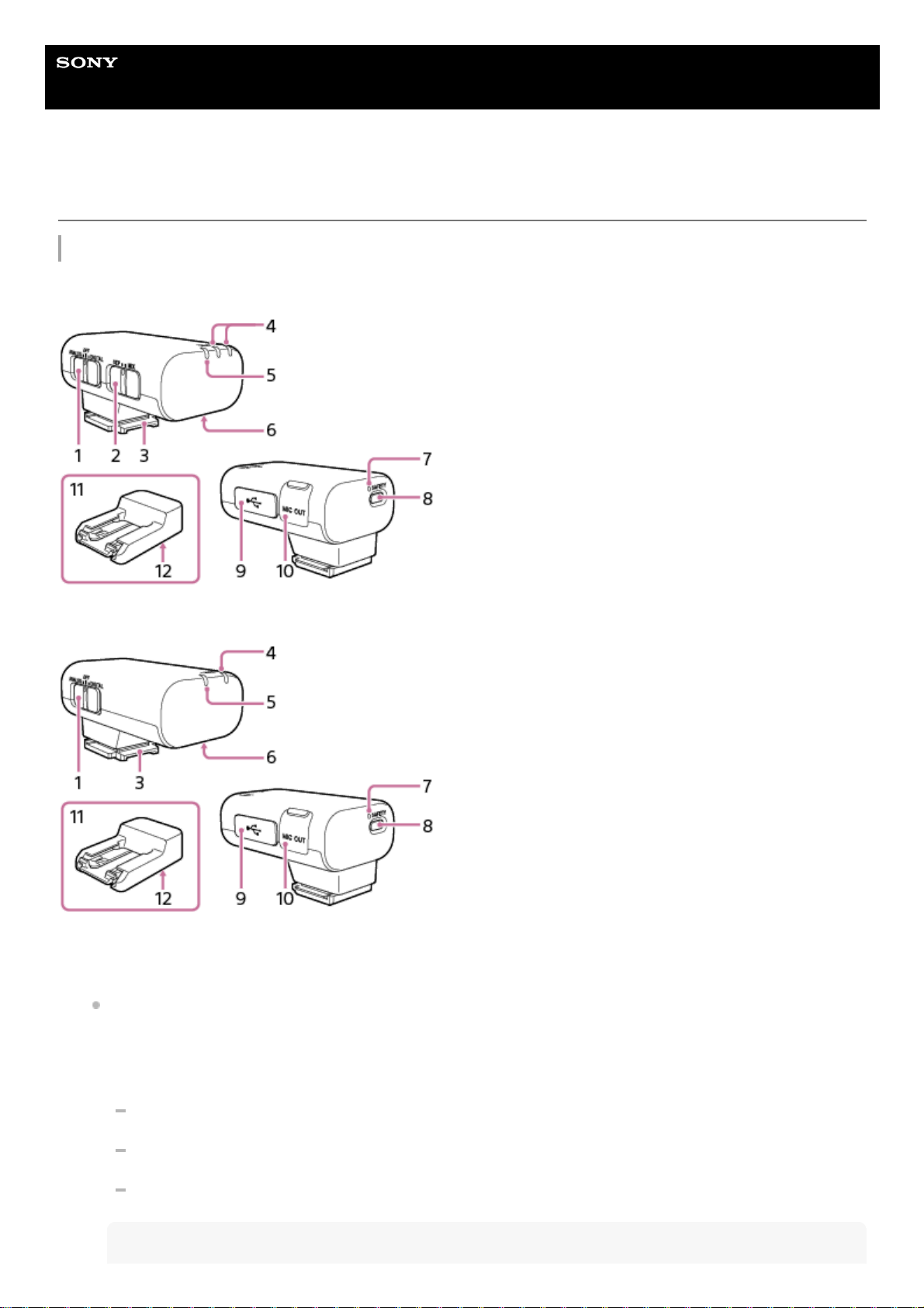
Locating parts and controls
Receiver
ECM-W3
ECM-W3S
Slide switch (ANALOG/OFF/DIGITAL)
Select “ANALOG” (analog audio output), “OFF” (power off), or “DIGITAL” (digital audio output).
If your camera is compatible with the digital audio interface of the Multi Interface Shoe, set the switch to
“DIGITAL.”
Digital signal transmission from the receiver to the camera has the following merits over analog signal
transmission that is enabled by the switch being set to “ANALOG.”
Audio recording with less noises
Less audio delay during recording
Recording with 24-bit audio (only available in combination with the compatible camera)
Note
1.
3

Movies recorded with 24-bit audio may not be played back normally on devices or software incompatible with 24-bit
audio, resulting in unexpectedly loud volumes or no sound.
If your camera is not compatible with the digital audio interface of the Multi Interface Shoe, set the switch to
“ANALOG.”
When the message “This accessory is not supported by the device and cannot be used.” is displayed on the
camera, set the switch to “ANALOG.”
If this does not help, see here.
When a TRS audio cable with the 3.5 mm diameter plug (commercially available) is connected, the receiver
outputs analog signals via the cable.
When a device with a USB audio input capability is connected, the receiver outputs digital signals.
When you do not intend to use the receiver, set the switch to “OFF” to conserve the battery power.
Mode switch (SEP/MIX) (ECM-W3)
By selecting a receiver mode with this switch before you start video recording with the camera, you can make
recordings with audio from either of the two microphones individually as the left or right channel audio; or recordings
with mixed audio from the two microphones.
2.
Multi Interface foot3.
LINK (LINK1/LINK2) lamp (ECM-W3)
LINK lamp (ECM-W3S)
Indicates the connection state between the receiver and the microphone.
Hint
On the nameplate under the clip of the microphone, you will find either the number “1” or “2” indicated for microphone
identification. The number “1” indicates the microphone No. 1; and the number “2” indicates the microphone No. 2. To identify
which microphone connection is active with the receiver, check the state of the LINK1 lamp for the microphone No. 1 and the
LINK2 lamp for the microphone No. 2 on the receiver. (Applicable to ECM-W3)
4.
Power lamp (Green: Powered, Orange: Charging the battery)
Indicates the power state of the receiver or the battery charge state.
When the power lamp stays blinking in orange, battery charging is needed.
5.
Charging connector
Supplies power to the receiver for battery charging via the charging case.
6.
SAFETY lamp
Lights in yellow when the receiver goes into SAFETY mode and goes out when the receiver comes out of the mode.
7.
SAFETY button
Pressing and holding the SAFETY button for about 2 seconds places the receiver into SAFETY mode.
For details, see About the SAFETY button.
8.
USB Type-C® port
Connect to a power source with a USB Type-C cable (commercially available) for charging the built-in battery of the
receiver and/or for supplying power to the receiver.
This port can be connected to a device with a USB audio input capability, such as a computer or a smartphone, for
audio recording as well.
9.
Microphone out jack
Connect to the microphone in jack on the camera with a TRS audio cable with the 3.5 mm diameter plug
(commercially available) for audio recording.
10.
Connector Protect Holder/Stand
Attached to the receiver at the time of purchase.
11.
4
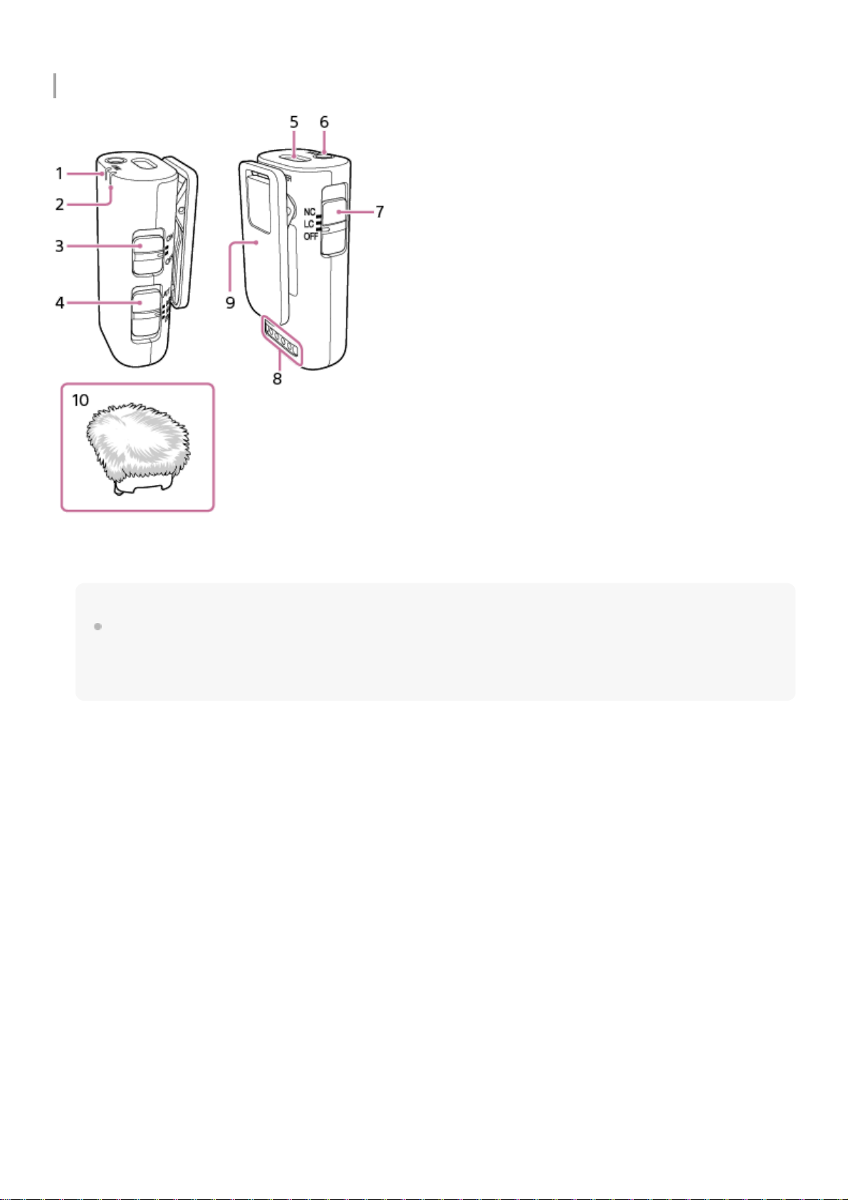
Microphone
Screw hole for tripod attachment (1/4 in. in diameter)12.
LINK lamp
Indicates the connection state between the receiver and the microphone.
Hint
On the nameplate under the clip of the microphone, you will find either the number “1” or “2” indicated for microphone
identification. The number “1” indicates the microphone No. 1; and the number “2” indicates the microphone No. 2. To identify
which microphone connection is active with the receiver, check the state of the LINK1 lamp for the microphone No. 1 and the
LINK2 lamp for the microphone No. 2 on the receiver. (Applicable to ECM-W3)
1.
Power lamp (Green: Powered, Orange: Charging the battery)
Indicates the power state of the microphone or the battery charge state.
When the power lamp stays blinking in orange, battery charging is needed.
2.
Power switch
When you do not intend to use the microphone, select “OFF” with this switch to conserve the battery power.
3.
ATT switch
Select the option suitable for the audio recording volume. To record loud sounds while minimizing distortion, select
“20dB.” To record quiet sounds, select “0dB.” “10dB” is the recommended volume level for recording human voices. It
is recommended that you select an option while monitoring the volume level meter on the camera or the audio
recording volume with headphones.
4.
Internal microphone5.
External microphone input jack (monaural)
Connecting an external microphone (not supplied) to this jack automatically switches the audio input source to the
connected external microphone.
6.
Filter switch (NC/LC/OFF)
NC: Select this option to use the noise cut filter function. Unpleasant noises are effectively eliminated by digital signal
processing. If the sound quality does not seem appropriate, select “OFF.”
7.
5
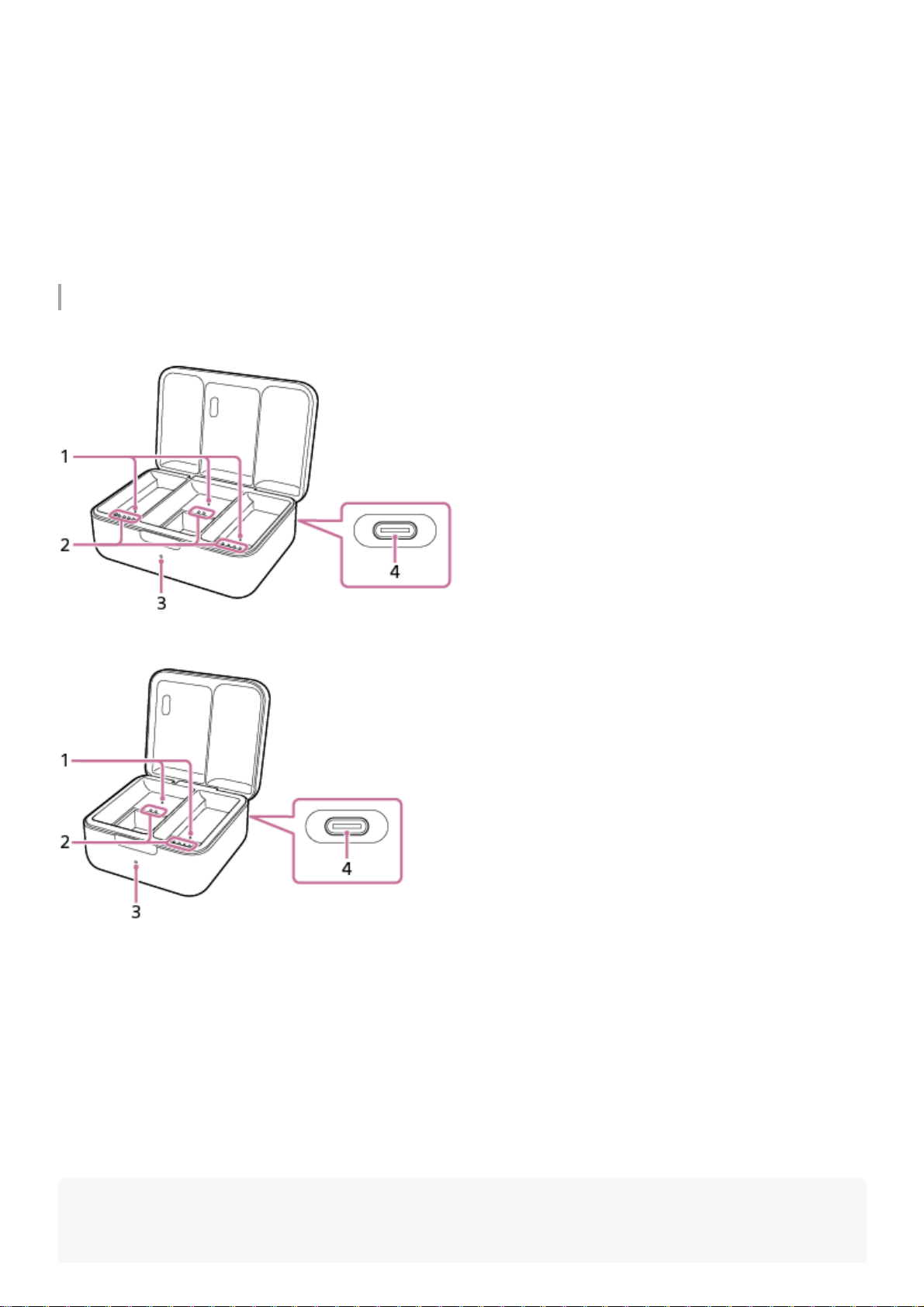
Charging case
ECM-W3
ECM-W3S
Note
LC: Select this option to use the low cut filter function. Unwanted noises, such as wind noises, air-conditioning
noises, and vibration noises, are minimized.
OFF: Select this option to disable either of the filter functions.
Charging connector
Supplies power to the microphone for battery charging via the charging case.
8.
Clip
Use this clip for attaching the microphone to your clothing.
9.
Wind screen
Attach the wind screen to the microphone to reduce noises caused by breath or strong wind.
10.
Detection pin
Detects when the receiver and the microphone are both housed in the charging case.
1.
Charging connector2.
Charging lamp
Indicates the battery charging state of the charging case.
3.
USB Type-C® port
Connect to a power source with a USB Type-C cable (commercially available) for charging the built-in batteries of the
charging case as well as of the receiver and the microphone housed in the case.
4.
6

To prevent a malfunction, do not deliberately push in the detection pin and/or any of the charging connectors unless you intend to
place the receiver and the microphone in the charging case.
Related Topic
Charging the built-in batteries
Attaching the wind screen
Attaching the connector protect holder/stand
About the mode switch (ECM-W3)
About the SAFETY button
Recording
Lamp indications
5-055-395-11(1) Copyright 2023 Sony Corporation
7

Help Guide
Wireless Microphone
ECM-W3 / ECM-W3S
Unpacking
If you find anything missing, please contact your dealer.
The number in the parentheses indicates the quantity.
ECM-W3
Receiver (1)
Connector Protect Holder/Stand (attached) (1)
Microphone (2)
Charging case (1)
Wind screen (2)
Pouch (1)
Set of printed documentation
ECM-W3S
Receiver (1)
Connector Protect Holder/Stand (attached) (1)
Microphone (1)
Charging case (1)
Wind screen (1)
Pouch (1)
Set of printed documentation
5-055-395-11(1) Copyright 2023 Sony Corporation
8

Help Guide
Wireless Microphone
ECM-W3 / ECM-W3S
Charging the built-in batteries
Each of the receiver, the microphone, and the charging case contains a built-in lithium-ion rechargeable battery. Connect
the charging case and a power source with a USB Type-C cable (commercially available) for battery charging.
Note
Before charging the built-in batteries, be sure to turn off the receiver and the microphone.
Battery charging can go on while the receiver and the microphone are turned on. However, placing the receiver and the
microphone in the charging case automatically turns them off. This means that the next time you use the receiver and the
microphone, you must select “OFF” once with the slide switch on the receiver and with the power switch on the microphone, and
then turn them back on.
In the event that the receiver and the microphone are removed from the charging case after battery charging is conducted while
the receiver and the microphone are turned on, placing them back in the charging case without changing the switch selection
does not start battery charging.
Place the receiver and the microphone in the charging case.
Note
Be sure to push in the microphone until it clicks into place. When the microphone is properly seated, its power lamp lights in
orange, indicating that the battery charging has started.
ECM-W3
ECM-W3S
1
9
About the battery charging time
In the event of charging the built-in batteries while the receiver and the microphone are housed in the charging case, the
built-in batteries of the receiver, the microphone, and the charging case are simultaneously charged via the USB
connection.
About 10 minutes of battery charging enables about 30 minutes of use of the receiver and the microphone.
Time period required to fully charge the built-in batteries of the receiver and the microphone: about 2 hours*
Time period required to fully charge the built-in battery of the charging case: about 2 hours and 30 minutes*
Charging the built-in batteries of the receiver and the microphone while on the go
The charging case contains a rechargeable battery. By having it charged in advance, you can charge the batteries of the
receiver and the microphone when you have no access to a power source, for example, while you are on the go.
ECM-W3
The fully charged battery power of the charging case is sufficient for about 1 time charging for all the built-in batteries
of the receiver, the microphone No. 1, and the microphone No. 2 from the empty state to the fully charged state.
ECM-W3S
The fully charged battery power of the charging case is sufficient for about 2 times charging for the built-in batteries
of the receiver and the microphone from the empty state to the fully charged state.
Notes on charging the built-in batteries of the receiver and the microphone while on the go
In the event that the charging lamp on the charging case is blinking in orange when the receiver and the microphone are
removed from the charging case, the rechargeable battery of the charging case is running out of power. Charge the
battery of the charging case.
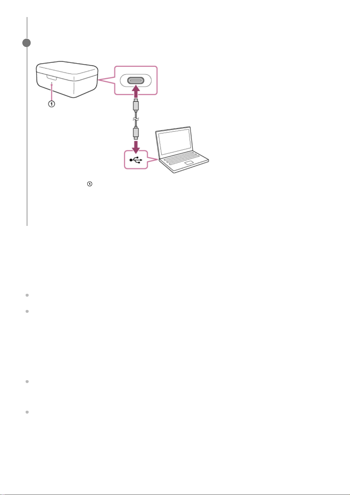
When the receiver and the microphone are properly housed in the charging case, close the lid of the case.
Connect the USB Type-C port on the back of the charging case and a power source with a USB Type-C
cable for battery charging.
The charging lamp ( ) on the charging case lights in orange, indicating that battery charging has started.
When the built-in battery of the charging case is fully charged, the charging lamp on the charging case goes out
regardless of the battery charging states of the receiver and the microphone housed in the charging case. When
the USB Type-C cable is disconnected at this point, battery charging for the receiver and the microphone continues
with the battery power of the charging case.
2
Time period required for charging the empty rechargeable batteries via the USB charging port (CDP - Charging Downstream Port) on the
computer to full capacity. It may vary depending on the using condition.
*
10
This manual suits for next models
1
Table of contents
Other Sony Microphone manuals


