Introduction
oo...
cesses
O
tue
tA
ie
Po
MAA
Sa
PRO
L:
3
The
WRT-81
OA
and
the
WRT-820A
are
transmitters
for
an
800
MHz
.
Features
.....
band
UHF
synthesized
wireless
microphone
system
to
be
used
for
Precautions
Se
broadcast
or
movie
production
purposes.
The
other
system
compo-
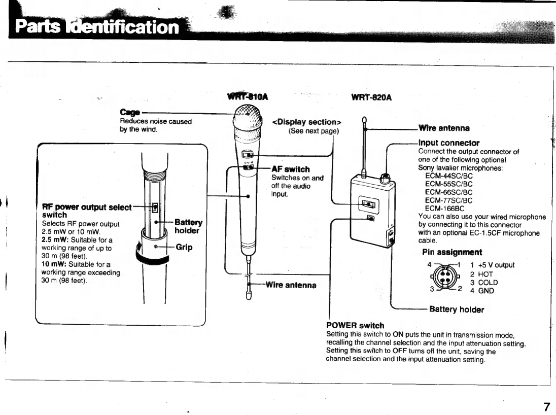
Parts
Identification
..............ooconcnnnonncananoraconnorononnccnnornnnonanncrnon
canon
ancnnno
nos
7
nents
include
the
AN-820A
UHF
antemna,
the
WD-820A
UHF
antenna
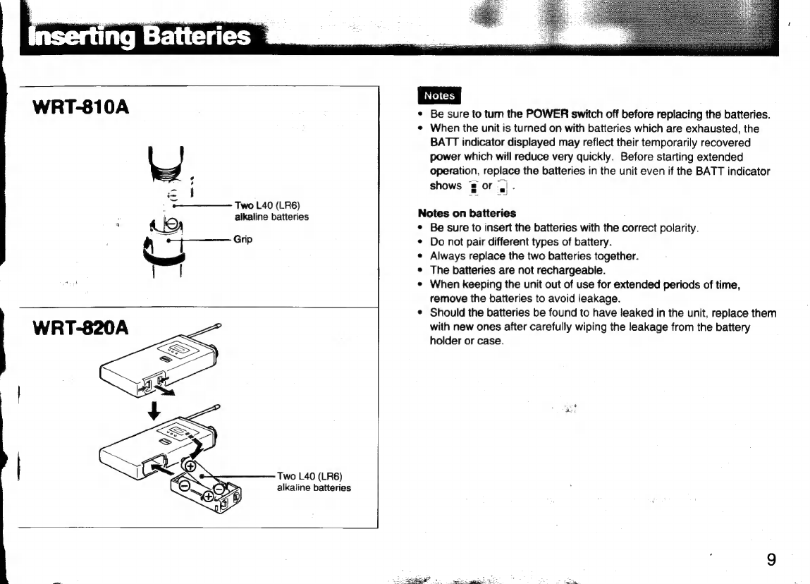
Inserting
Bate
ES
coco
cani
nin
oè
as
is
nw
ae
oye
e
EEEE
9
divider,
and
the
WRR-820A/840A
UHF
synthesized
diversity
tuner.
Changing
the
Channel
Selection
.........
Changing
the
Input
Attenuation
Setting
...
Using
the
Microphone/Transmitter
.......
The
microphones/transmitters
and
tuners
are
classified
by
frequency
band.
See
the
table
on
the
next
page.
A
OO
A
12
MHz
frequency
band
(or
two
consecutive-numbered
TV
channels)
Channels
and
Carrier
Frequencies
......ooocococonocconoccnocnnnocononorancnananinnnanos
is
assigned
to
each
microphone/transmitter
and
tuner
model.
To
Block
Diagram...
¿icono
dos
indicate
the
assigned
frequency
bands,
the
parenthesized
numbers
following
the
model
names
in
the
table
show
the
smaller
of
the
assigned
TV
channel
numbers.
In
building
up
a
UHF
wireless
microphone
e
system,
be
sure
to
combine
a
microphone/transmitter
and
a
tuner
E
>
.
having
the
same
TV
channel
number.
8
=
‘
~
a
sa
w
A
Pa
`
A
A
ou
i
^
ai
`.
`
l
À
3
PRESI