Sony WRT-867A User manual

UHF SynthesizedWireless Microphone
1995 by Sony Corporation
3-798-105-12 (1)
Model:
WRT-867A
Operating Instructions
Before using the unit, please read this manual thoroughly and
retain it for future reference.

2
Notes on Use ...................................................................... 3
Introduction ...................................................................... 3
Features ............................................................................. 4
Parts Identification ........................................................... 5
Operation........................................................................... 6
Inserting the Battery....................................................... 6
Changing the Channel Selection .................................... 7
Channels and Carrier Frequencies ................................. 9
Notes on Microphone System Operation ..................... 10
Changing the Input Attenuation...................................10
Error Codes .................................................................. 10
Specifications................................................................... 11
Table of Contents

3
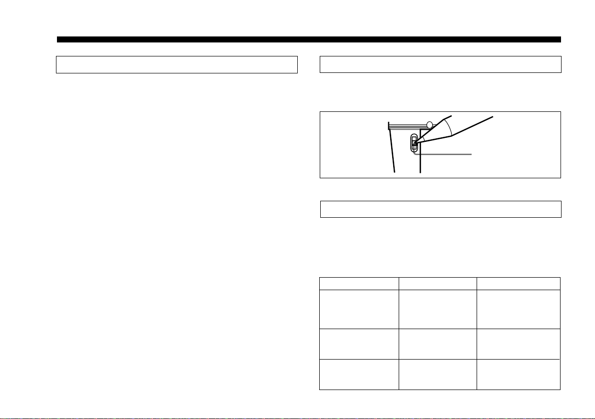
•When holding the microphone, do not hook your fingers
on the antenna, or touch or cover the antenna with your
hands.
Doing so can weaken the signal, resulting in noise.
•The unit is designed for use in an ambient temperature
range of 0°C to 50°C (32°F to 122°F).
•Do not place the unit on or near a heat source such as
lighting equipment or a power amplifier, or in a place
subject to direct sunlight or excessive moisture. In such
places, the external finish or internal parts of the unit may
be damaged.
•If the unit is used in a very humid or dusty place or in a
place subject to an active gas, clean its surface as well as
the connectors with a dry, soft cloth soon after use.
Lengthy use of the unit in such places or not cleaning it
after its use in such places may shorten its life.
•When cleaning the unit, never use organic solvents such
as thinners or benzine, which will damage the finish of
the unit.
•The unit has been factory adjusted precisely. Do not
tamper with its internal parts or attempt to repair it.
Notes on Use Introduction
The WRT-867A is a wireless microphone for an 800 MHz
band UHF synthesized wireless microphone system to be
used for broadcast or movie production purpose. The other
system components include the WRT-810A UHF
Synthesized Wireless Microphone, the WRT-820A UHF
Synthesized Transmitter, the AN-820A UHF Antenna, the
WD-820A UHF Antenna Divider, the WRR-810A UHF
Synthesized Tuner, and the WRR-840A/860A UHF
Synthesized Diversity Tuner.
The microphones/transmitters and tuners are classified by
frequency band. See the table below.
A 14 MHz frequency band (or two consecutive-numbered
TV channels) is assigned to each microphone/transmitter
and tuner model. To indicate the assigned frequency bands,
the parenthesized numbers following the model names in
the table show the smaller of the assigned TV channel
numbers.
792.250 – 798.500
799.250 – 805.500
Frequency (MHz)
WRR-810A(66)
WRR-840A(66)a)
WRR-860A(66)
Tuner
WRT-810A(66)
WRT-820A(66)
WRT-867A(66)
Transmitter or
microphone
Model name
66
67
TV
channel
Frequency band
a) For this model, the AN-820A UHF Antenna is required.
If necessary, also use the WD-820A UHF Antenna Divider.

4
Easy operation on 102 channels
The microphone uses a PLL (phase-locked loop)
synthesizer for operation on 102 channels (at 125 kHz
intervals), with simple button operations to change
channels.
Compact design
The unit has a slim and lightweight design, ideal for
popular music vocals on television.
Long operation on LR6 battery
The microphone operates for approximately four hours (at
normal operating temperatures) on one alkaline battery
(LR6).
New dynamic unit and rigid body
The newly-developed dynamic unit and rigid body produce
a rich and balanced sound with no rumble. Particularly
suited to stage vocals, where it provides clear and easy-on-
the-ear sound.
Features
Built-in attenuator
The attenuator can be set to 0, 6 or 12 dB by a switch
operation.
Wide dynamic range and low noise
The compander system enables transmission with a wide
dynamic range and low noise susceptibility.

5
Parts Identification
Antenna
Cage
Grip
Model number indication
Antenna
Power indicator
View from underside
LCD window
Channel setting
buttons
Attenuator switch
Serial number label
Battery
compartment

6
Operation
Inserting the Battery
The microphone operates for approximately four hours (at
normal operating temperatures) on one Sony AM3 alkaline
battery (LR6).
The microphone starts operating as soon as you insert the
battery.
2Insert the battery with the negative terminal downward,
and push it firmly into the battery compartment against
the spring.
The power indicator on the bottom of the microphone
lights in red, and the LCD window shows the currently
selected channel number.
To change the channel selection, see the section
“Changing the Channel Selection” on the next page.
3Replace the grip.
Note
Check that the battery is correctly in place before replacing
the grip. If you try to force the grip back on while the
battery is not properly in the battery compartment, it is
possible for the outer casing of the battery to be damaged
and cause a short-circuit.
Inserting the battery
1Twist the grip counterclockwise and slide down.
Grip
Battery
Battery
compartment
+
12
Grip LR6 battery
Battery
compartment

7
Battery replacement
Using a Sony alkaline battery, the microphone operates for
approximately four hours at normal operating temperatures.
After about three and a half hours of continuous operation,
the power indicator (red) on the bottom of the microphone
goes off, indicating that the battery level is low. When this
happens, replace the battery as soon as possible.
Notes on the battery
•Use a new alkaline battery, and check the recommended
use-by date on the bottom of the battery.
•Be careful to insert the battery with the correct polarity.
•When not using the microphone for a long period,
remove the battery. If there should be leakage from the
battery, wipe the battery compartment clean before
inserting a new battery. If the leakage is serious, consult
your Sony dealer.
Changing the Channel Selection
When you insert a battery in the microphone, the currently
selected transmission channel number appears in the LCD
window. To change the channel selection, the microphone
must be in the channel setting mode, in which the LCD
indication flashes.
There are two cases in which the microphone enters the
channel setting mode:
•Immediately after the battery is inserted
•If you hold down the + or – channel setting button for at
least 0.5 seconds
Flashing channel indication (66-01 in the example shown)
In the channel setting mode, to avoid interference with
other equipment in the vicinity, the antenna is powered off.
CH
+
Indication flashes in
channel setting mode.

8
To set the channel
1Press the + or – channel setting button to change the
indication.
If you hold the button down, the numbers change more
rapidly.
Notes
•Make sure that the channel selected is the same as that
selected on the tuner unit used in the same system.
•Depending on the noise or interference conditions, the
selectable channels may not necessarily all be usable. If
necessary, you can determine the usable channels by
stepping the channel selection through a number of
channels on the tuner with the microphone/transmitter set
to OFF. Those channels on which the RF indicator of the
tuner does not light are usable.
•If there is a TV broadcasting station nearby, to avoid
possible interference with broadcasting, do not use that
station’s channel.
66-02
• • •
66-50 66-51
• • •
67-01 67-02
• • •
67-50
+ button
– button
66-01 67-51
2Release the button, and wait for about 3 seconds. The
indication stops flashing, and the microphone starts
transmitting on the new channel.
Saving the channel setting in memory
The new channel setting is automatically saved in an
internal memory, and the setting is retained if you remove
the battery. However, if you remove the battery while in
the channel setting mode, the flashing channel number is
not saved in memory, and the original setting is unchanged.
Operation

9
Channels and Carrier Frequencies
66-01 792.250
66-02 792.375
66-03 792.500
66-04 792.625
66-05 792.750
66-06 792.875
66-07 793.000
66-08 793.125
66-09 793.250
66-10 793.375
66-11 793.500
66-12 793.625
66-13 793.750
66-14 793.875
66-15 794.000
66-16 794.125
66-17 794.250
66-18 794.375
66-19 794.500
66-20 794.625
66-21 794.750
66-22 794.875
66-23 795.000
66-24 795.125
66-25 795.250
66-26 795.375
66-27 795.500
66-28 795.625
66-29 795.750
66-30 795.875
66-31 796.000
66-32 796.125
66-33 796.250
66-34 796.375
66-35 796.500
66-36 796.625
66-37 796.750
66-38 796.875
66-39 797.000
66-40 797.125
66-41 797.250
66-42 797.375
66-43 797.500
66-44 797.625
66-45 797.750
66-46 797.875
66-47 798.000
66-48 798.125
66-49 798.250
66-50 798.375
66-51 798.500
Frequency (MHz)
TV-66 Band
Channel Frequency (MHz)
TV-66 Band
Channel Frequency (MHz)
TV-66 Band
Channel Frequency (MHz)
TV-66 Band
Channel
67-01 799.250
67-02 799.375
67-03 799.500
67-04 799.625
67-05 799.750
67-06 799.875
67-07 800.000
67-08 800.125
67-09 800.250
67-10 800.375
67-11 800.500
67-12 800.625
67-13 800.750
67-14 800.875
67-15 801.000
67-16 801.125
67-17 801.250
67-18 801.375
67-19 801.500
67-20 801.625
67-21 801.750
67-22 801.875
67-23 802.000
67-24 802.125
67-25 802.250
67-26 802.375
67-27 802.500
67-28 802.625
67-29 802.750
67-30 802.875
67-31 803.000
67-32 803.125
67-33 803.250
67-34 803.375
67-35 803.500
67-36 803.625
67-37 803.750
67-38 803.875
67-39 804.000
67-40 804.125
67-41 804.250
67-42 804.375
67-43 804.500
67-44 804.625
67-45 804.750
67-46 804.875
67-47 805.000
67-48 805.125
67-49 805.250
67-50 805.375
67-51 805.500

10
Notes on Microphone System Operation
•In a system using twelve or fewer microphones, maintain
a distance of at least 30 cm (1 ft) between each pair of
microphones, and a distance of at least 3 m (10 ft)
between each microphone and its receiving antenna.
For details of operation with two or more channels, refer
to the Operating Instructions for the WRR-810A UHF
Synthesized Tuner and the WRR-840A/860A UHF
Synthesized Diversity Tuner.
•Ensure that the tuners set to channels not being used are
either turned off or set to the minimum output level (the
LEVEL adjustment knob set to MIN).
•When powering the microphone on or off, to keep the
noise to a minimum, set the audio output level from the
tuner or mixer to a minimum.
•Powering the microphone on without checking the
channel selection first may interfere with the operation of
other microphones/transmitters, if the current setting is
already being used.
Changing the Input Attenuation
Select an attenuation of 0, 6 or 12 dB according to the input
sound level.
Attenuator switch
0
-6
-12
Error Codes
In addition to the normal channel indication, the following
error codes may appear in the LCD window.
Error codes
Error code
Err 1
Err 2
Err 3
Meaning
An error occurred in
the data in backup
memory.
A fault occurred in
the PLL synthesizer
circuit.
Battery voltage
exceeds the
specified limit.
Required action
The data is
reinitialized. Reinsert
the battery, and set
the channel again.
Consult your Sony
dealer.
Use the correct
battery.
Operation

11
Specifications
General
Operating temperature
0°C to 50°C (32°F to 122°F)
Storage temperature –30°C to +60°C (–22°F to +140°F)
Dimensions
Including antenna51 mm (dia.) ×228 mm (length)
(2 1/8×9 inches)
Excluding antenna
51 mm (dia.) ×195 mm (length)
(2 1/8×7 3/4inches)
Mass About 325 g (11.5 oz)
(including battery)
Supplied accessories Microphone holder (1)
Stand adaptor PF 1/2to NS 5/8(1)
Stand adaptor PF 1/2to W 3/8(1)
Design and specifications are subject to change without
notice.
Transmitter and Modulator Section
Oscillator Crystal controlled PLL synthesizer
Carrier frequencies 792.250 to 805.500 MHz
(102 settings at 125 kHz intervals)
Tone signal 32.768 kHz
Type of emission 110KF3E
RF power output 10 mW (50 ohms)
Frequency stability Within ±0.005%
Spurious radiation Less than 2.5 µW
Antenna type 1/4wavelength helical
Pre-emphasis 50 µs
Reference deviation ±5 kHz
Frequency response 50 Hz to 15 kHz
Signal-to-noise ratio More than 60 dB (A-weighted, with
reference deviation at WRR-820A/
840A/860A)
Audio attenuator 0, 6, 12 dB
Maximum input sound pressure level
142 dB SPL (at 12 dB attenuation)
Microphone unit Dynamic type
Power Section
Power requirements 1.5 V DC (L40 (LR6) alkaline battery)
Battery life About 4 hours at 25°C or 77°F
(with Sony AM3 (LR6) alkaline
battery)
Current consumptionLess than 240 mA (at 1.5 V)


Sony Corporation Printed in Japan
Table of contents
Other Sony Microphone manuals

Sony
Sony XA-MC10 User manual

Sony
Sony ECM-W1M User manual

Sony
Sony ECM S80 User manual

Sony
Sony ECM-T110 User manual

Sony
Sony ECM-HGZ1 User manual

Sony
Sony ECM-T115 User manual

Sony
Sony C800GPAC User manual

Sony
Sony ECM-999 User manual

Sony
Sony ECMMS907 - Stereo Type Mic User manual

Sony
Sony ECM-B1M User manual