Sony MDS-S9 User manual

SERVICE MANUAL
Ver 1.0 2001.06
MINIDISC DECK
AEP Model
UK Model
SPECIFICATIONS
MDS-S9
Model Name Using Similar Mechanism MDS-S50
MD Mechanism Type MDM-7A
Optical Pick-up Name KMS-260B
System MiniDisc digital audio
system
Disc MiniDisc
Laser Semiconductor laser (λ=
780 nm) Emission
duration: continuous
Laser output MAX 44.6 µW
1)
1) This output is the value measured at a distance of
200 mm from the objective lens surface on the
Optical Pick-up Block with 7 mm aperture.
Laser diode Material: GaAlAs
Revolutions (CLV) 400 rpm to 900 rpm
Error correction ACIRC (Advanced Cross
Interleave Reed Solomon
Code)
Sampling frequency 44.1 kHz
Coding ATRAC (Adaptive
TRansform Acoustic
Coding)/ATRAC 3
Modulation system EFM (Eight-to-Fourteen
Modulation)
Number of channels 2 stereo channels
Frequency response 5 to 20,000 Hz ±0.3 dB
Signal-to-noise ratio Over 96 dB during play
Wow and flutter Below measurable limit
Inputs
ANALOG IN Jack type: phono
Impedance: 47 kilohms
Rated input: 500 mVrms
Minimum input:
125 mVrms
DIGITAL IN Connector type: square
optical
Impedance: 660 nm
(optical wave length)
Outputs
ANALOG OUT Jack type: phono
Rated output: 2 Vrms (at
50 kilohms)
Load impedance: over 10
kilohms
General
Power requirements 230 V AC, 50/60Hz
Power consumption 15 W
0.5 W (at the STANDBY
mode)
Dimensions (approx.) 280 ×83 ×290 mm (w/
h/d) incl. projecting parts
and controls
Mass (approx.) 2.4 kg
Supplied accessories
Audio connecting cords (2)
Optical cable (1)
Remote commander (remote) (1)
R6 (size-AA) batteries (2)
Design and specifications are subject to change
without notice.
US and foreign patents licensed from Dolby
Laboratories.
9-873-914-11 Sony Corporation
2001F0500-1 Home Audio Company
C2001.6 ShinagawaTec Service Manual Production Group

2
MDS-S9
PROCEDURE FOR USINGTHE SELF-DIAGNOSIS FUNCTION (ERROR HISTORY DISPLAY MODE)
Note: Perform the self-diagnosis function in the “error history display mode”in the test mode. The following describes the least required procedure. Be
careful not to enter other modes by mistake. If you set other modes accidentally, press the MENU/NO button to release the mode.
1. While pressing the [ AMS ] knob and xbutton simultaneously, connect the power plug to the outlet, and release the
[ AMS ] knob and xbutton simultaneously to display “[Check]”.
2. Turn the [ AMS ] knob and when “[Service]”is displayed, press the [YES] button to display “AUTO CHECK”(C01).
3. Turn the [ AMS ] knob to display “Err Display”(C02).
4. Press the [YES] button to sets the error history mode and displays “op rec tm”.
5. Select the contents to be displayed or executed using the [ AMS ] knob.
6. Press the [ AMS ] knob to display or execute the contents selected.
7. Press the [ AMS ] knob another time returns to step 4.
8. Press the [MENU/NO] button to display “Err Display”(C02) and release the error history mode.
9. To release the test mode, press the I/1button. The unit sets into the STANDBY state, and the test mode ends.
SELF-DIAGNOSIS FUNCTION
The deck’s self-diagnosis function
automatically checks the condition of the MD
deck when an error occurs, then issues a three-
or five-digit code and an error message on the
display. If the code and message alternate, find
them in the following table and perform the
indicated countermeasure. Should the problem
persist, consult your nearest Sony dealer.
C11/Protected
,Take out the MD and close the record-protect
slot.
C12/Cannot Copy
•You tried to record a CD with a format that the
external device connected to the deck does not
support, such as CD-ROM or video CD.
,Remove the disc and insert a music CD.
C13/REC Error
,Set the deck in a stable surface, and repeat the
recording procedure.
•The inserted MD is dirty (with smudges,
fingerprints, etc.), scratched, or substandard in
quality.
,Replace the disc and repeat the recording
procedure.
C13/Read Error
,Take out the MD and insert it again.
C14/TOC Error
,Insert another disc.
,If possible, erase all the tracks on the MD.
C41/Cannot Copy
•The sound source is a copy of commercially
available music software, or you tried to record a
CD-R (Recordable CD).
,The Serial Copy Management System
prevents making a digital copy. You cannot
record a CD-R.
C71/Din Unlock
•The sporadic appearance of this message is
caused by the digital signal being recorded. This
will not affect the recording.
•While recording from a digital component
connected through the DIGITAL IN connector,
the digital connecting cable was unplugged or the
digital component turned off.
,Connect the cable or turn the digital
component back on.
. >
. >
. >
. >
. >
. >
. >

3
MDS-S9
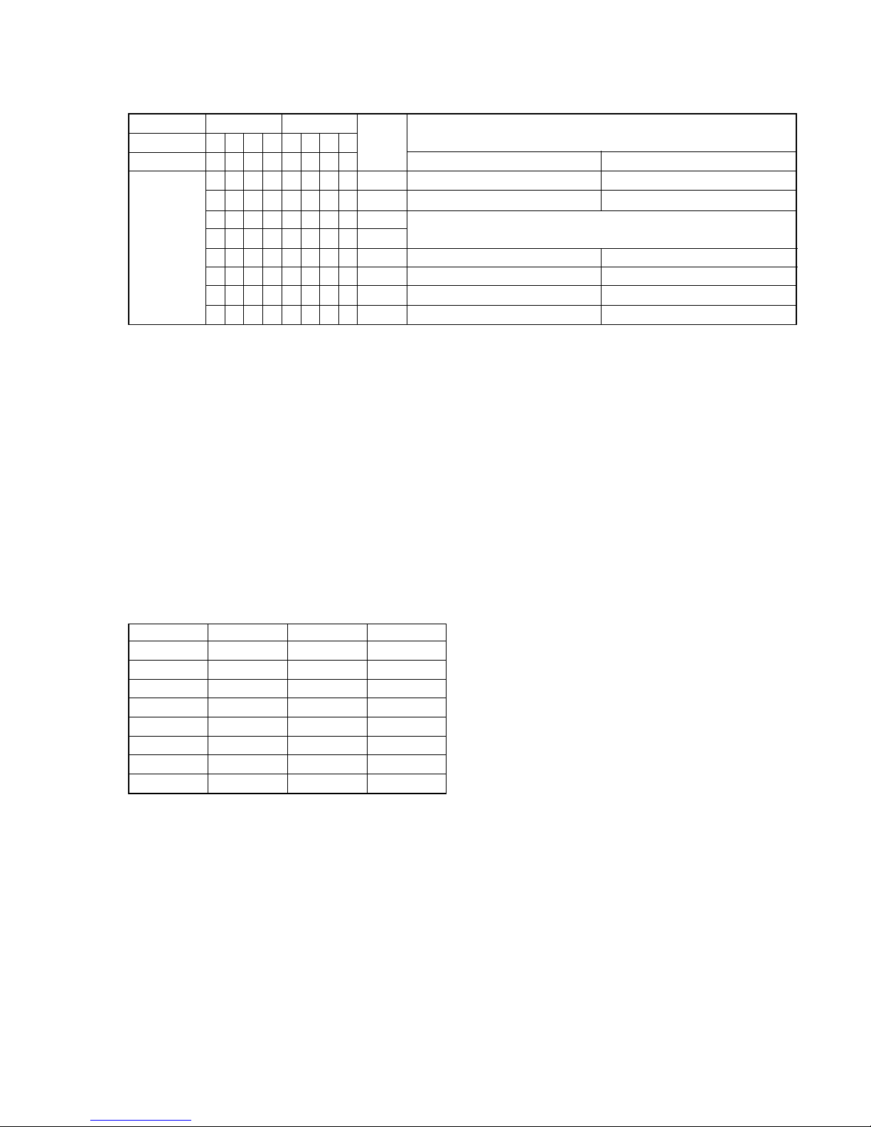
ITEMS OF ERROR HISTORY MODE ITEMS AND CONTENTS
Display Details of History
op rec tm Cumulative recording time is displayed.
When cumulative recording time is over 1 minute, the hour and minute are displayed as they are.
When it is under 1 minute, “Under 1 min”is displayed.
The displayed time is the total time the laser is set to the high power state.
This is about 1/4 of the actual recording time. The time is displayed in decimal digits.
op play tm Cumulative playing time is displayed.
When cumulative playing time is over 1 minute, the hour and minute are displayed as they are.
When it is under 1 minute, “Under 1 min”is displayed.
The displayed time is the total of the actual play time. Pauses are not counted.
The time is displayed in decimal digits.
spdl rp tm Cumulative spindle motor running time is displayed.
When cumulative spindle motor run time is over 1 minute, the hour and minute are displayed as they are.
When it is under 1 minute, “Under 1 min”is displayed.
The time is displayed in decimal digits.
retry err Displays the total number of retries during recording and number of retry errors during playback.
Displayed as “r ss p ss”.
“r”indicates the retries during recording while “p”indicates the retry errors during playback.
The number of retries and retry errors are displayed in hexadecimal digits from 00 to FF.
total err Displays the total number of errors.
Displayed as “total ss”.
The number of errors is displayed in hexadecimal digits from 00 to FF.
err history Displays the 10 latest errors.
Displayed as “0sErrCd @@”.
sindicates the history number. The smaller the number, the more recent is the error. (00 is the latest)
@@ indicates the error code.
Refer to the following table for the details. The error history can be switched by turning the [ AMS ]
knob.
retry adrs Display the 5 latest retry address.
Display as “ss ADRS@@@@”.
ss indicates the history number. The smaller the number, the more recent is the error. (00 is the latest)
@@@@ indicates the cluster of retry address.
The number of retry address can be switched by turning the [ AMS ] knob.
er refresh Mode to clear the error history and retry address history.
Procedure:
1) Press the [ AMS ] button.
2) The display will change to “er refresh?”, and then press the [YES] button.
The operation is over if “Complete!”is displayed.
After this mode was executed, check the following:
•The data have been cleared.
•Perform the recording and playing to check that the mechanism operates normally.
op change Mode to clear cumulative time of “op rec tm”and “op play tm”.
These historical data are used to determine the timing when the optical pick-up is to be replaced. When the
optical pick-up was replaced, perform this operation to clear historical data.
Procedure:
1) Press the [ AMS ] button.
2) The display will change to “op chang?”, and then press the [YES] button.
The operation is over if “Complete!”is displayed.
spdl change Mode to clear cumulative time of “spdl rp tm”.
This historical data is used to determine the timing when the spindle motor is to be replaced. When the spindle
motor was replaced, perform this operation to clear historical data.
Procedure:
1) Press the [ AMS ] button.
2) The display will change to “spdl chang?”, and then press the [YES] button.
The operation is over if “Complete!”is displayed.
. >
. >
. >
. >
. >

4
MDS-S9
Error Code Details of Error
10 Loading failed
12 Loading switch combination is illegal
20 Head of PTOC could not be read within the
specified time
21 Head of PTOC could be read but its content is
erroneous
22 Access to UTOC could not be made within the
specified time
23 UTOC could be not read within the specified
time
24 Content of UTOC is erroneous
30 Playing could not start
31 Content of sector is erroneous
40 Cause of retry occurred during normal recording
41 D-RAM overflowed and retry was executed
42 Retry was executed during the writing to TOC
43 S.F editing was interrupted by retry
50 Address could not be read except in access
processing
51 Focusing failed and it is out of control
60 Unlock retry
Table of Error Codes

5
MDS-S9
TABLE OF CONTENTS
SELF-DIAGNOSIS FUNCTION.................................... 2
1. SERVICING NOTES ............................................... 6
2. GENERAL ................................................................... 10
3. DISASSEMBLY
3-1. Disassembly Flow ........................................................... 12
3-2. Case ................................................................................. 13
3-3. MD Mechanism Deck (MDM-7A) ................................. 13
3-4. MAIN Board ................................................................... 14
3-5. BD Board......................................................................... 14
4. TEST MODE.............................................................. 15
5. ELECTRICAL ADJUSTMENTS......................... 20
6. DIAGRAMS
6-1. Block Diagram –SERVO Section –............................... 31
6-2. Block Diagram –MAIN Section –................................. 32
6-3. Note for Printed Wiring Boards and
Schematic Diagrams ....................................................... 33
6-4. Printed Wiring Boards –BD Board –............................. 35
6-5. Schematic Diagram –BD Board (1/2) –........................ 36
6-6. Schematic Diagram –BD Board (2/2) –........................ 37
6-7. Printed Wiring Board
–MAIN Board (Component Side) –.............................. 38
6-8. Printed Wiring Board
–MAIN Board (Conductor Side) –................................ 39
6-9. Schematic Diagram –MAIN Board (1/3) –................... 40
6-10. Schematic Diagram –MAIN Board (2/3) –................... 41
6-11. Schematic Diagram –MAIN (3/3)/PT Boards –............ 42
6-12. Printed Wiring Board –PT Board –............................... 43
6-13. Printed Wiring Board –DISPLAY Board –................... 44
6-14. Schematic Diagram –DISPLAY Board –...................... 45
6-15. IC Pin Function Description ........................................... 46
7. EXPLODED VIEWS
7-1. Case Section .................................................................... 52
7-2. Front Panel Section ......................................................... 53
7-3. Mechanism Deck Section-1 (MDM-7A) ........................ 54
7-4. Mechanism Deck Section-2 (MDM-7A) ........................ 55
8. ELECTRICAL PARTS LIST ............................... 56
SAFETY-RELATED COMPONENT WARNING!!
COMPONENTS IDENTIFIED BY MARK 0OR DOTTED
LINE WITH MARK 0ON THE SCHEMATIC DIAGRAMS
AND IN THE PARTS LIST ARE CRITICAL TO SAFE
OPERATION. REPLACE THESE COMPONENTS WITH
SONY PARTS WHOSE PART NUMBERS APPEAR AS
SHOWN IN THIS MANUAL OR IN SUPPLEMENTS PUB-
LISHED BY SONY.
Notes on chip component replacement
•Never reuse a disconnected chip component.
•Notice that the minus side of a tantalum capacitor may be dam-
aged by heat.
Flexible Circuit Board Repairing
•Keep the temperature of the soldering iron around 270 ˚C dur-
ing repairing.
• Do not touch the soldering iron on the same conductor of the
circuit board (within 3 times).
• Be careful not to apply force on the conductor when soldering
or unsoldering.
This appliance is classified
as a CLASS 1 LASER
product.
The CLASS 1 LASER
PRODUCT MARKING is
located on the rear exterior.
The following caution label is located inside the unit.
ADVARSEL
Eksplosjonsfare ved feilaktig skifte av batteri.
Benytt samme batteritype eller en tilsvarende type
anbefalt av apparatfabrikanten.
Brukte batterier kasseres i henhold til fabrikantens
instruksjoner.
VARNING
Explosionsfara vid felaktigt batteribyte.
Använd samma batterityp eller en likvärdig typ som
rekommenderas av apparattillverkaren.
Kassera använt batteri enligt gällande föreskrifter.
VAROITUS
Paristo voi räjähtää, jos se on virheellisesti asennettu.
Vaihda paristo ainoastaan laitevalmistajan suosittelemaan tyyppiin.
Hävitäkäytetty paristo valmistajan ohjeiden mukaisesti.
ADVARSEL!
Lithiumbatteri-Eksplosionsfare ved fejlagtig håndtering.
Udskiftning måkun ske med batteri
af samme fabrikat og type.
Levér det brugte batteri tilbage til leverandøren.
CAUTION
Danger of explosion if battery is incorrectly replaced.
Replace only with the same or equivalent type recommended by
the manufacturer.
Discard used batteries according to the manufacturer’s instructions.
CAUTION
Use of controls or adjustments or performance of procedures
other than those specified herein may result in hazardous ra-
diation exposure.

6
MDS-S9
JIG FOR CHECKING BD BOARD WAVEFORM
The special jig (J-2501-196-A) is useful for checking the waveform of the BD board. The names of terminals and the checking items to be
performed are shown as follows.
I+3V : For measuring IOP (Check the deterioration of the optical pick-up laser)
IOP : For measuring IOP (Check the deterioration of the optical pick-up laser)
GND : Ground
TE : Tracking error signal (Traverse adjustment)
FE : Focus error signal
VC : Reference level for checking the signal
RF : RF signal (Check jitter)
I+3V
CN105
IOPTE VC
GNDFE RF
I+3V
IOP
GND
TE
FE
VC
RF
I+3V
IOP
GND
TE
FE
VC
RF
1
7
for
MDM-7
A
NOTES ON HANDLING THE OPTICAL PICK-UP
BLOCK OR BASE UNIT
The laser diode in the optical pick-up block may suffer electro-
static break-down because of the potential difference generated
by the charged electrostatic load, etc. on clothing and the human
body.
During repair, pay attention to electrostatic break-down and also
use the procedure in the printed matter which is included in the
repair parts.
The flexible board is easily damaged and should be handled with
care.
NOTES ON LASER DIODE EMISSION CHECK
Never look into the laser diode emission from right above when
checking it for adjustment. It is feared that you will lose your sight.
SECTION 1
SERVICING NOTES

7
MDS-S9
IOP DATA RECORDING AND DISPLAY WHEN OPTICAL PICK-UP AND NON-VOLATILE MEMORY (IC195
OF BD BOARD) ARE REPLACED
The IOP value labeled on the optical pick-up can be recorded in the non-volatile memory. By recording the value, it will eliminate the need
to look at the value on the label of the optical pick-up. When replacing the optical pick-up or non-volatile memory (IC195 of BD board),
record the IOP value on the optical pick-up according to the following procedure.
Record Precedure:
1. While pressing the [ AMS ] knob and xbutton simultaneously, connect the power plug to the outlet, and release the [ AMS ]
knob and xbutton simultaneously to display “[Check]”.
2. Turn the [ AMS ] knob to display “[Service]”, and press the [YES] button to display “AUTO CHECK”(C01).
3. Turn the [ AMS ] knob to display “Iop Write”(C05), and press the [YES] button.
4. The display becomes “Ref=@@@.@”(@ is an arbitrary number) and the numbers which can be changed will blink.
5. Input the IOP value written on the optical pick-up.
To select the number : Turn the [ AMS ] knob.
To select the digit : Press the [ AMS ] knob.
6. When the [YES] button is pressed, the display becomes “Measu=@@@.@”(@ is an arbitrary number).
7. As the adjustment results are recorded for the 6 value. Leave it as it is and press the [YES] button.
8. “Complete!!”will be displayed momentarily. The value will be recorded in the non-volatile memory and the display will become“Iop
Write”(C05).
9. Press the I/1button to complete.
Display Precedure:
1. While pressing the [ AMS ] knob and xbutton simultaneously, connect the power plug to the outlet, and release the [ AMS ]
knob and xbutton simultaneously to display “[Check]”.
2. Turn the [ AMS ] knob to display “[Service]”, and press the [YES] button to display “AUTO CHECK”(C01).
3. Turn the [ AMS ] knob to display “Iop Read”(C26), and press the [YES] button.
4. “@@.@/##.#”is displayed and the recorded contents are displayed.
@@.@: indicates the IOP value labeled on the optical pick-up.
##.# : indicates the IOP value after adjustment
5. To end, press the [ AMS ] knob or [MENU/NO] button to display “Iop Read”(C26). Then press the I/1button.
WHEN MEMORY NG IS DISPLAYED
If the nonvolatile memory data is abnormal, “E001 MEMORY NG”will be displayed so that the MD deck does not continue operations.
In this case, set the test mode promptly and perform the following procedure.
Procedure:
1. Enter the test mode (refer to page 15).
2. Normally a message for selecting the test mode will be displayed. However if the nonvolatile memory is abnormal, the following will be
displayed “INIT EEP?”.
3. Press the both xand Zbuttons simultaneously.
4. Turn the [ AMS ] knob to display “MDM-7A”.
5. Press the [ AMS ] button. If the nonvolatile memory is successfully overwritten, the normal test mode will be set and a message to
select the test mode will be displayed.
FORCE RESET
You can reset the microprocessor of the system with following procedure.
Use this method if the device cannot be operated normaly because the microprocessor is hung up or with some reasons.
Procedure:
Remove the short pin attached on CN420, then install it again.
. > . >
. >
. >
. >
. >
. > . >
. >
. >
. >
. >
. >
CN420
–MAIN BOARD (Component Side) –

8
MDS-S9
RETRY CAUSE DISPLAY MODE IN MD
•In this test mode, the causes for retry of the unit during recording and stop can be displayed on the liquid crystal display. During
playback, the “track mode”for obtaining track information will be set.
This is useful for locating the faulty part of the unit.
•The following will be displayed :
During recording and stop: Retry cause, number of retries, and number of retry errors.
During playback : Information such as type of disc played, part played, copyright.
These are displayed in hexadecimal.
Precedure:
1. Keep the xbutton pressed for about 10 seconds, or press the [LEVER/DISPLAY/CHAR] button while pressing xand [MENU/NO]
buttons.
2. “RTs00c00e000”is displayed after the mode is set.
3. Press the zbutton go into recording mode, then press the ubutton to start recording.
4. To check “track mode”, press the ubutton to playback.
5. To release the test mode, press the I/1button and turn off the power. Remove the power plug from the outlet after “TOC”is turned
off. If you cannot release the test mode, refer to “FORCE RESET”on page 7.
Fig. 1 Reading theTest Mode Display
(During recording and stop)
RTs@@c##e***
Liquid crystal display
@@ : Cause of retry
## : Number of retries
***: Number of retry errors
Fig. 2 Reading theTest Mode Display
(During playback)
@@ ###** $$
Liquid crystal display
@@ : Parts No. (Name of area named on TOC)
### : Cluster Address (Physical address on the
** : Sector disc)
$$ : Track mode (Track information such as copy-
right information of each part)
Reading the Retry Cause Display
84218421
b7 b6 b5 b4 b3 b2 b1 b0
00000001
00000010
00000100
00001000
00010000
00100000
01000000
10000000
Hexa-
decimal Cause of Retry
01
02
04
08
10
20
40
80
Higher Bits Lower Bits
Hexadecimal
Bit
Binary shock
ader5
Discontinuous address
DIN unlock
FCS incorrect
IVR rec error
CLV unlock
Access fault
Occurring conditions
When track jump (shock) is detected
When ADER was counted more than five times
continuously
When ADIP address is not continuous
When DIN unlock is detected
When not in focus
WhenABCD signal level exceeds the specified range
When CLV is unlocked
When access operation is not performed normally
Reading the Display:
Convert the hexadecimal display into binary display. If more than two causes, they will be added.
Example
When 42 is displayed:
Higher bit: 4 = 0100 tb6
Lower bit : 2 = 0010 tb1
In this case, the retry cause is combined of “CLV unlock”and “ader5”.
When A2 is displayed:
Higher bit: A = 1010 tb7 + b5
Lower bit : 2 = 0010 tb1
The retry cause in this case is combined of “Access fault”, “IVR rec error”, and “ader5”.

9
MDS-S9
Reading the Retry Cause Display
84218421
b7 b6 b5 b4 b3 b2 b1 b0
00000001
00000010
00000100
00001000
00010000
00100000
01000000
10000000
Hexa-
decimal Details
01
02
04
08
10
20
40
80
Higher Bits Lower Bits
Hexadecimal
Bit
Binary When 0
Emphasis OFF
Monaural
This is 2-bit display. Normally 01.
01: Normal audio. Others: Invalid
Audio (Normal)
Original
Copyright
Write prohibited
When 1
Emphasis ON
Stereo
Invalid
Digital copy
No copyright
Write allowed
Reading the Display:
Convert the hexadecimal display into binary display. If more than two causes, they will be added.
Example When 84 is displayed:
Higher bit: 8 = 1000 tb7
Lower bit : 4 = 0100 tb2
In this case, as b2 and b7 are 1 and others are 0, it can be determined that the retry cause is combined of “Emphasis OFF”, “Monaural”,
“Original”, “Copyright”, and “Write allowed”.
Example When 07 is displayed:
Higher bit: 0 = 0000 tAll 0
Lower bit : 7 = 0111 tb0 + b1 + b2
In this case, as b0, b1, and b2 are 1 and others are 0, it can be determined that the retry cause is combined of “Emphasis ON”, “Stereo”,
“Original”, “Copyright”, and “Write prohibited”.
Hexadecimal
t
Binary ConversionTable
Hexadecimal Binary Hexadecimal Binary
0 0000 8 1000
1 0001 9 1001
2 0010 A 1010
3 0011 B 1011
4 0100 C 1100
5 0101 D 1101
6 0110 E 1110
7 0111 F 1111

10
MDS-S9
AMS qd (8)(10)(12)(13)(16)
(24)
CLEAR 8(7)(16)(18)(24)
Display qf (8) (17)
INPUT qh (8)
LEVEL/DISPLAY/CHAR 2(8)
(12) (24)
MD insertion slot 4(16)
MD LP indicator qg (10) (17)
MENU/NO 6(10) (18) (20)
PLAY MODE qk (16)
REC MODE qj (9)
Remote sensor 3(7)
YES 7(10) (18) (20)
?/1 (power)/STANDBY indicator
1(8) (16)
Z(eject) 5(8) (17)
m(go back)/M(go forward)
9(16) (17) (18) (24)
z(recording) 0(8) (10)
x(stop) qa (7) (8) (16)
NX (play/pause) qs (8) (16)
BUTTON DESCRIPTIONS
SECTION 2
GENERAL This section is extracted from
instruction manual.
LOCATION OF CONTROLS
–Front Panel –
–Back Panel –
AC power cordPC LINK
to a wall outlet
Amplifier,
etc.
CD player, DBS
tuner, etc.1)
1) Digital equipment with a DIGITAL OUT
connector only

11
MDS-S9
AyBqs (16)
CD PLAYER .(go back)/>(go forward) ql
(15)
CD-SYNCHRO STANDBY/START/STOP 7(14)
(15)
CLEAR 6(16) (18) (24)
DISPLAY ws (8) (12)
FADER 3(28)
INPUT wf (8)
Letter/number buttons 5(17) (25)
LEVEL +/– qa (12)
MENU/NO w; (10) (18) (20)
MUSIC SYNC 8(14)
NAME EDIT/SELECT wa (24)
PLAY MODE 2(16)
REC MODE wg (9)
REPEAT qd (16)
SCROLL wd (17)
T.REC qj (13)
YES 4(10) (18) (20)
?/1 (power) 1(8) (16)
X(pause) 9(8) (16)
x(stop) 0(8) (16)
m(fast reverse)/M(fast forward) qf (16) (17)
(18) (24)
.(go back)/>(go forward) qg (8) (10) (16)
(17) (25) (26)
z(recording) qh (8) (10)
H(play) qk (8) (16)
A(eject) wh (8) (17)
Remote control
BUTTON DESCRIPTIONS

MDS-S9
12
•This set can be disassembled in the order shown below.
3-1. DISASSEMBLY FLOW
SECTION 3
DISASSEMBLY
3-2. CASE
(Page 13)
Set
3-4. MAIN BOARD
(Page 14)
3-3. MD MECHANISM DECK
(MDM-7A)
(Page 13)
3-5. BD BOARD
(Page 14)

MDS-S9
13
3-3. MD MECHANISM DECK (MDM-7A)
Note: Follow the disassembly procedure in the numerical order given.
3-2. CASE
2
case
1
two screws (case 3 TP2)
1
two screws (case 3 TP2)
3
four screws (BVTTWH M3)
1
wire (flat type) (23 core)
(CN400)
1
wire (flat type) (27 core
)
(CN1)
2
harness
4
MD mechanism deck
(MDM-7A)

MDS-S9
14
3-4. MAIN BOARD
3-5. BD BOARD
3
three screw
s
(BVTP3
×
8)
4
two screws
(BVTP3
×
8)
5
MAIN board
1
wire (flat type) (15 core)
(CN490)
2
connector (CN902)
1
wire (flat type) (23 core)
(CN103)
2
wire (flat type) (27 core)
(CN102)
7
BD board
3
connector
(CN104)
8
flexible board (CN101)
4
Remove five solders.
5
Remove four solders.
BD board
– CONDUCTOR SIDE VIEW –
6
two screws (2
×
6)

15
MDS-S9
SECTION 4
TEST MODE
4-1. PRECAUTIONS FOR USE OFTEST MODE
•As loading related operations will be performed regardless of the test mode operations being performed, be sure to check that the disc
is stopped before setting and removing it.
Even if the Zbutton is pressed while the disc is rotating during continuous playback, continuous recording, etc., the disc will not stop
rotating.
Therefore, it will be ejected while rotating.
Be sure to press the Zbutton after pressing the [MENU/NO] button and the rotation of disc is stopped.
4-1-1. Recording laser emission mode and operating buttons
•Continuous recording mode (CREC 1MODE)
•Laser power check mode (LDPWR CHECK)
•Laser power adjustment mode (LDPWRADJUST)
•Comparison with initial Iop value written in nonvolatile memory (Iop Compare)
•Write current Iop value in read nonvolatile memory using microprocessor (Iop NV Save)
•Traverse (MO) check (EF MO CHECK)
•Traverse (MO) adjustment (EF MO ADJUST)
•When pressing the zbutton.
4-2. SETTINGTHE TEST MODE
The following are two methods of entering the test mode.
Procedure 1: While pressing the [ AMS ] knob and xbutton simultaneously, connect the power plug to the outlet, and release
the [ AMS ] knob and xbutton.
When the test mode is set, “[Check]”will be displayed. Turning the [ AMS ] knob between the following three
groups; ···Tt [Check] Tt [Service] Tt [Develop] Tt ···.
Procedure 2: While pressing the [ AMS ] knob, connect the power plug to the outlet, and release the [ AMS ] knob.
When the test mode is set, “TEMP CHECK”(C12) will be displayed. By setting the test mode using this method, only the
“Check”group of procedure1 can be executed.
Note: Do not use the test mode in the [Develop] group.
If used, the unit may not operate normally.
If the [Develop] group is set accidentally, press the [MENU/NO] button immediately to release the [Develop] group.
4-3. RELEASINGTHETEST MODE
Press the I/1button. The unit sets into the STANDBY state, and the test mode ends.
4-4. BASIC OPERATIONS OF THETEST MODE
All operations are performed using the [ AMS ] knob, [YES] button, and [MENU/NO] button.
The functions of knob and buttons are as follows.
Function name Function
[ AMS ] knob Changes parameters and modes
[YES] button Proceeds onto the next step. Finalizes input
[MENU/NO] button Returns to previous step. Stops operations
. >
. >
. >
. >
. >
. >
. >

16
MDS-S9
4-5. SELECTINGTHETEST MODE
There are 26 types of test modes as shown below. The groups can be switched by turning the [ AMS ] knob.After selecting the
group to be used, press the [YES] button.After setting a certain group, turning the [ AMS ] knob switches modes shown below.
Refer to “Group”in the table for details can be selected.
All items used for servicing can be treated using group [Service]. So be carefully not to enter other groups by mistake.
Note: Do not use the test mode in the [Develop] group.
If used, the unit may not operate normally.
If the [Develop] group is set accidentally, press the [MENU/NO] button immediately to exit the [Develop] group.
•For details of each adjustment mode, refer to “5. Electrical Adjustments”.
For details of “Err Display”, refer to “Self-Diagnosis Function”on page 2.
•If a different mode has been selected by mistake, press the [MENU/NO] button to release that mode.
•Modes with (×) in the Mark column are not used for servicing and therefore are not described in detail. If these modes are set acciden-
tally, press the [MENU/NO] button to release the mode immediately.
Display
AUTO CHECK
Err Display
TEMP ADJUST
LDPWRADJUST
Iop Write
Iop NV Save
EF MO ADJUST
EF CD ADJUST
FBIAS ADJUST
AG Set (MO)
AG Set (CD)
TEMP CHECK
LDPWR CHECK
EF MO CHECK
EF CD CHECK
FBIAS CHECK
ScurveCHECK
VERIFYMODE
DETRK CHECK
0920 CHECK
Iop Read
Iop Compare
ADJ CLEAR
INFORMATION
CPLAY1MODE
CREC 1MODE
Details
Automatic self-diagnosis
Error history display, clear
Temperature compensation offset adjustment
Laser power adjustment
Iop data writing
Writes current Iop value in read nonvolatile memory using microprocessor
Traverse (MO) adjustment
Traverse (CD) adjustment
Focus bias adjustment
Auto gain output level adjustment (MO)
Auto gain output level adjustment (CD)
Temperature compensation offset check
Laser power check
Traverse (MO) check
Traverse (CD) check
Focus bias check
S-curve check
Nonvolatile memory check
Detrack check
Most circumference check
Iop data display
Comparison with initial Iop value written in nonvolatile memory
Initialization of nonvolatile memory for adjustment values
Display of microprocessor version, etc.
Continuous playback mode
Continuous recording mode
No.
C01
C02
C03
C04
C05
C06
C07
C08
C09
C10
C11
C12
C13
C14
C15
C16
C17
C18
C19
C25
C26
C27
C28
C31
C34
C35
Mark Group
Check Service
. >
. >

17
MDS-S9
4-5-1. Operating the Continuous Playback Mode
1. Entering the continuous playback mode
(1) Set the disc in the unit. (Whichever recordable discs or discs for playback only are available)
(2) Turn the [ AMS ] knob to display “CPLAY1MODE”(C34).
(3) Press the [YES] button to change the display to “CPLAY1MID”.
(4) When access completes, the display changes to “C = AD = )”.
Note: The numbers “ ” displayed show you error rates and ADER.
2. Changing the parts to be played back
(1) Press the [YES] button during continuous playback to change the display as below.
When pressed another time, the parts to be played back can be moved.
(2) When access completes, the display changes to “C = AD = )”.
Note: The numbers “ ” displayed show you error rates andADER.
3. Ending the continuous playback mode
(1) Press the [MENU/NO] button. The display will change to “CPLAY1MODE”(C34).
(2) Press the Zbutton and take out the disc.
Note: The playback start addresses for IN, MID, and OUT are as follows.
IN : 40h cluster
MID : 300h cluster
OUT : 700h cluster
4-5-2. Operating the Continuous Recording Mode (Use only when performing self-recording/palyback check)
1. Entering the continuous recording mode
(1) Set a recordable disc in the unit.
(2) Turn the [ AMS ] knob to display “CREC 1MODE”(C35).
(3) Press the [YES] button to change the display to “CREC 1MID”.
(4) When access completes, the display changes to “CREC 1( )”and “REC ”lights up.
Note: The numbers “ ” displayed shows you the recording position addresses.
2. Changing the parts to be recorded
(1) When the [YES] button is pressed during continuous recording, the display changes as below.
When pressed another time, the parts to be recorded can be changed. “REC ”goes off.
(2) When access completes, the display changes to “CREC 1( )”and “REC ”lights up.
Note: The numbers “ ” displayed shows you the recording position addresses.
3. Ending the continuous recording mode
(1) Press the [MENU/NO] button. The display changes to “CREC 1MODE”(C35) and “REC
”goes off.
(2) Press the Zbutton and take out the disc.
Note 1: The recording start addresses for IN, MID, and OUT are as follows.
IN : 40h cluster
MID : 300h cluster
OUT : 700h cluster
Note 2: The [MENU/NO] button can be used to stop recording anytime.
Note 3: Do not perform continuous recording for long periods of time above 5 minutes.
Note 4: During continuous recording, be careful not to apply vibration.
4-6. FUNCTIONS OF OTHER BUTTONS
Function
u
x
M
m
REC MODE
PLAY MODE
LEVEL/DISPLAY/CHAR
Z
I/1
“CPLAY1MID”t“CPLAY1OUT”t“CPLAY1IN”
“CREC 1MID”t“CREC 1OUT”t“CREC 1IN”
Contents
Sets continuous playback when pressed in the STOP state. When pressed during continuous playback,
the tracking servo turns ON/OFF
Stops continuous playback and continuous recording
The sled moves to the outer circumference only when this is pressed
The sled moves to the inner circumference only when this is pressed
Switches between the pit and groove modes when pressed
Switches the spindle servo mode (CLV S yCLV A)
Switches the displayed contents each time the button is pressed
Ejects the disc
Releases the test mode
. >
. >

18
MDS-S9
Contents
4-7. TEST MODE DISPLAYS
Each time the [LEVEL/DISPLAY/CHAR] button is pressed, the display changes in the following order.
When CPLAY or CREC are started, the display will forcibly be switched to the error rate display as the initial mode.
1. Mode display
Displays “TEMP ADJUST”(C03), “CPLAY1MODE”(C34), etc.
2. Error rate display
Displays the error rate in the following way.
C = AD = )
C = : Indicates the C1 error.
AD = : Indicates ADER.
3. Address display
The address is displayed as follows. (MO: recordable disc, CD: playback only disc)
h = s = (MO pit and CD)
h = a = (MO groove)
h = : Indicates the header address.
s = : Indicates the SUBQ address.
a = : Indicates the ADIP address.
Note: “–” is displayed when the address cannot be read.
MEANINGS OF OTHER DISPLAYS
Mode display
Error rate display
Address display
Auto gain display
(Not used in servicing)
Detrack check display
(Not used in servicing)
IVR display
(Not used in servicing)
C1 error and jitter display
(Not used in servicing)
AD error and jitter display
(Not used in servicing)
Servo OFF
Tracking servo ON
Recording mode OFF
CLV normal mode
Tracking offset cancel OFF
Groove
Low reflection
CLV A
CLV UNLOCK
When Off
Display When Lit
Servo ON
Tracking servo OFF
Recording mode ON
CLV low speed mode
ABCD adjustment completed
Tracking offset cancel ON
Tracking auto gain OK
Focus auto gain OK
Pit
High reflection
CLV S
CLV LOCK
N
X
REC
SYNC
L. SYNC
OVER
B/1
A-/REP
TRACK/LP4
DISC/LP2
SHUF/SLEEP
MONO

19
MDS-S9
4-8. AUTOMATIC SELF-DIAGNOSIS FUNCTION
This test mode performs CREC and CPLAY automatically for mainly checking the characteristics of the optical pick-up.
To perform this test mode, the laser power must first be checked.
Perform AUTO CHECK after the laser power check and Iop Compare.
Procedure:
1. Turn the [ AMS ] knob to display “AUTO CHECK”(C01).
2. Press the [YES] button. If “LDPWR ”is displayed, it means that the laser power check has not been performed. In this case,
perform the laser power check and Iop Compare, and then repeat from enter the test mode.
3. If a disc is in the mechanical deck, it will be ejected forcibly.
“DISC IN”will be displayed in this case. Load a test disc (MDW-74/GA-1) which can be recorded.
4. If a disc is loaded at step 3, the check will start automatically.
5. When “XX CHECK”is displayed, the item corresponding to XX will be performed.
When “06 CHECK”completes, the disc loaded at step 3 will be ejected. “DISC IN”will be displayed. Load the check disc (TDYS-1).
6. When the disc is loaded in step 5, the check will automatically be resumed from “07 CHECK”.
7. After completing to test item 12, check OK or NG will be displayed. If all items are OK, “CHECKALL OK”will be displayed. If any item
is NG, it will be displayed as “NG:xxxx”.
When “CHECK ALL OK”is displayed, it means that the optical pick-up is normal. Check the operations of other parts (spindle motor,
sled motor, etc.).
When displayed as “NG:xxxx”, it means that the optical pick-up is faulty. In this case, replace the optical pick-up.
4-9. INFORMATION
Display the software version.
Procedure:
1. Turn the [ AMS ] knob to display “INFORMATION”(C31).
2. Press the [YES] button.
3. The software version will be displayed.
4. Press the [MENU/NO] button to end this mode.
. >
. >

20
MDS-S9 SECTION 5
ELECTRICAL ADJUSTMENTS
Other faults are suspected.
Check the mechanism parts (spindle motor, sled motor, etc.)
Start
NG
NG
NG
OK
OK
OK
Laser Power Check
5-7-2.
(See page 23)
5-7-3.
(See page 23)
5-7-4.
(See page 24)
Iop Compare
Auto Check Replace optical pick-up or MDM-7A
5-1. PARTS REPLACEMENT AND ADJUSTMENTS
If malfunctions caused by optical pick-up such as sound skipping are suspected, follow the following check.
Check before replacement
Table of contents
Other Sony Mini Disc Player manuals

Sony
Sony MZ-E80 User manual

Sony
Sony MZ-E800 User manual

Sony
Sony MZ-E10 User manual

Sony
Sony MDS-S40 User manual

Sony
Sony MZ-E700 User manual

Sony
Sony MD Walkman MZ-EP11 User manual

Sony
Sony MXD-D3 User manual

Sony
Sony MDS-S37 - Mini Disc Player User manual

Sony
Sony ZS-M1 User manual

Sony
Sony MDS-B6P User manual

Sony
Sony MDS-JE640 User manual

Sony
Sony MDX-F5800 Product guide

Sony
Sony ZS-M7 User manual

Sony
Sony MDX-C5970R User manual

Sony
Sony MZ-E32 User manual

Sony
Sony MZ-M200 Hi-MD Music Transfer Version 1 for Mac (User... User manual

Sony
Sony MZ-E500 User manual

Sony
Sony MZ-N707 OpenMG Jukebox NOTES on installing &... User manual

Sony
Sony MZ-N1 User manual

Sony
Sony MZ-E40 User manual