6
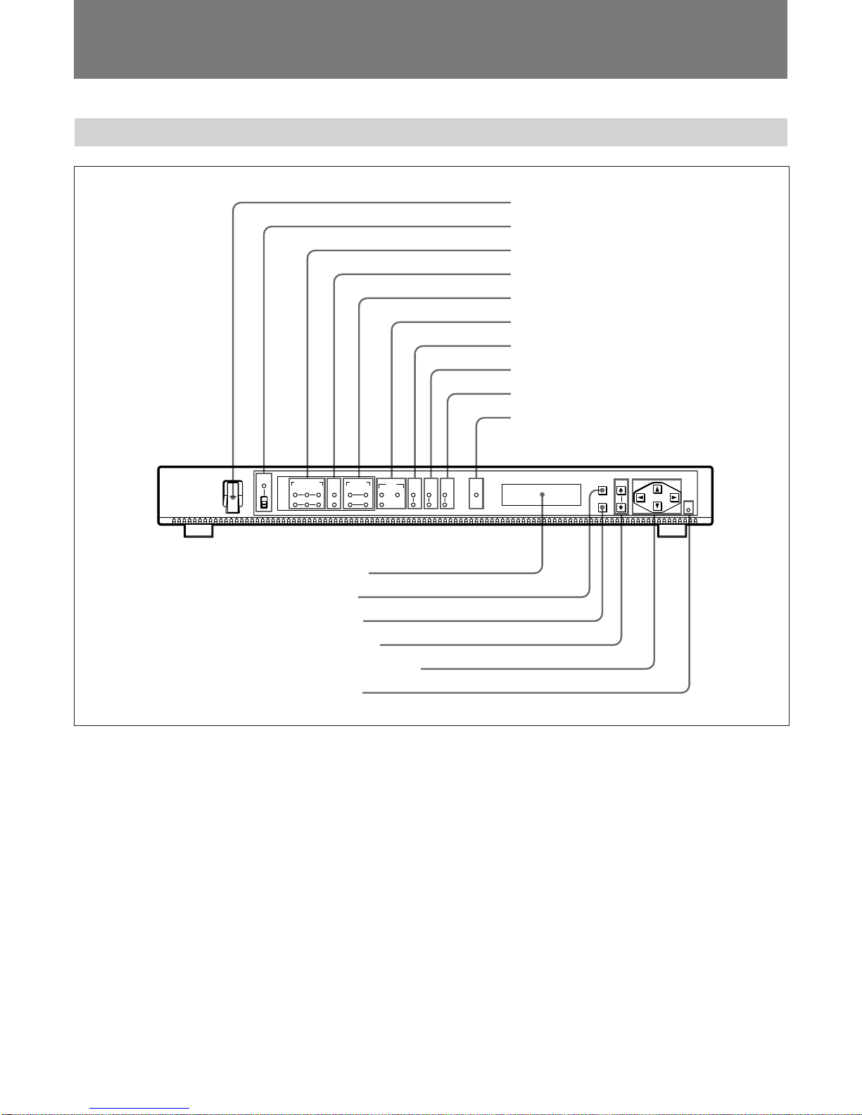
Locations and Functions of Parts and Controls
4INPUT SEL (input selection) indicators
IN1: Lights up when input signals from the optional
board in the IN1section are transmitted from the
IF OUT connector.
IN2: Lights up when input signals from the optional
board in the IN2section are transmitted from the
IF OUT connector.
When input signals from both optional boards are
simultaneously transmitted, both indicators light up.
To select from which optional board section input
signals are transmitted, select “01: INPUT SELECT”
in the menu.
When no signals are supplied to the selected board
slots, the indicator flashes. If the destination address
of the input signals and the address selected in the
menu are different when the BKSM-T101 SDTI Input
Board is installed, the indicator also flashes.
To select the address of this unit, select “43: My
ADDR-1”“53:MY ADDR-2” in the menu.
For more information, see “Menu Setup” (page 10).
5AUDIO SEL indicators
IN1 indicators
CH1/2: Lights up if input signals from the optional
board in the IN1section are transmitted when;
-The FEC RATE is 7/8
or
-The FEC RATE is 3/4 and IN1 AUDIO CH is
CH1/CH2.
CH3/4: Lights up if input signals from the optional
board in the IN1section are transmitted when;
-The FEC RATE is 7/8
or
-The FEC RATE is 3/4 and IN1 AUDIO CH is
CH3/CH4.
When the BKSM-T103 Analog Input Board is
installed and 3-pin XLR connectors are used, the
indicator does not light regardless of the FEC
RATE selection.
To select the FEC rate, select “12: FEC RATE” in the
menu.
To select the audio channels for the optional board in
the IN1section, select “47: IN1 AUDIO CH” in the
menu.
For more information, see “Menu Setup” (page 10).
IN2 indicators
CH1/2: Lights up if input signals from the optional
board in the IN2section are transmitted when;
-The FEC RATE is 7/8
or
-The FEC RATE is 3/4 and IN2 AUDIO CH is
CH1/CH2.
CH3/4: Lights up if input signals from the optional
board in the IN2section are transmitted when;
-The FEC RATE is 7/8
or
-The FEC RATE is 3/4 and IN2 AUDIO CH is
CH3/CH4.
When the BKSM-T103 Analog Input Board is
installed and 3-pin XLR connectors are used, the
indicator does not light up regardless of the
selection of the FEC RATE.
To select the FEC rate, select “12: FEC RATE” in the
menu.
To select the audio channels for the optional board in
the IN2section, select “57: IN2 AUDIO CH” in the
menu.
For more information, see “Menu Setup” (page 10).
6REF (reference signal) indicators
IN1: Lights up when the reference signals are video
signals from the input connectors of the optional
board in the IN1section.
IN2: Lights up when the reference signals are video
signals from the input connector of the optional
board in the IN2section.
EXT: Lights up when the reference signals are video
signals from the REF IN connector.
With no signal supplied to the selected input
connectors, the indicator flashes.
To select the reference signals, select “02: REF
SELECT” in the menu.
For more information, see “Menu Setup” (page 10).
7VIDEO STD (video standard) indicators
525: Lights up when the unit is set up in the 525
standard.
625: Lights up when the unit is set up in the 625
standard.
To select the broadcasting standard, select “03:
VIDEO STD” in the menu.
For more information, see “Menu Setup” (page 10).