Sony DSM-T1 User manual

DIGITAL SATELLITE MODULATOR
DSM-T1
INSTALLATION MANUAL
1st Edition
Serial No. 10001 and Higher

!WARNING
This manual is intended for qualified service personnel only.
To reduce the risk of electric shock, fire or injury, do not perform any servicing other than that
contained in the operating instructions unless you are qualified to do so. Refer all servicing to
qualified service personnel.
!WARNUNG
Die Anleitung ist nur für qualifiziertes Fachpersonal bestimmt.
Alle Wartungsarbeiten dürfen nur von qualifiziertem Fachpersonal ausgeführt werden. Um die
Gefahr eines elektrischen Schlages, Feuergefahr und Verletzungen zu vermeiden, sind bei
Wartungsarbeiten strikt die Angaben in der Anleitung zu befolgen.Andere als die angegeben
Wartungsarbeiten dürfen nur von Personen ausgeführt werden, die eine spezielle Befähigung
dazu besitzen.
!AVERTISSEMENT
Ce manual est destiné uniquement aux personnes compétentes en charge de l’entretien.Afin
de réduire les risques de décharge électrique, d’incendie ou de blessure n’effectuer que les
réparations indiquées dans le mode d’emploi à moins d’être qualifié pour en effectuer d’autres.
Pour toute réparation faire appel à une personne compétente uniquement.
For the customers in the U.S.A.
Attention-when the product is installed in Rack:
1. Prevention against overloading of branch circuit
When this product is installed in a rack and is
supplied power from an outlet on the rack, please
make sure that the rack does not overload the supply
circuit.
2. Providing protective earth
When this product is installed in a rack and is
supplied power from an outlet on the rack, please
confirm that the outlet is provided with a suitable
protective earth connection.
3. Internal air ambient temperature of the rack
When this product is installed in a rack, please make
sure that the internal air ambient temperature of the
rack is within the specified limit of this product.
4. Prevention against achieving hazardous
condition due to uneven mechanical loading
When this product is installed in a rack, please make
sure that the rack does not achieve hazardous
condition due to uneven mechanical loading.

1 (E)
DSM-T1
Table of Contents
Manual Structure
Purpose of this manual ........................................................................................ 3 (E)
Contents ............................................................................................................... 3 (E)
Related manuals................................................................................................... 3 (E)
1. Installation
1-1. Installation Environment .......................................................................1-1 (E)
1-2. Power Supply ........................................................................................1-1 (E)
1-2-1. Power Specifications ............................................................1-1 (E)
1-2-2. Power Cord...........................................................................1-1 (E)
1-3. External Dimensions and Installation Space.........................................1-2 (E)
1-4. Matching Connectors and Cables..........................................................1-3 (E)
1-5. Input and Output Signal of Connector ..................................................1-3 (E)
1-6. Internal Switches and Indicators ...........................................................1-4 (E)
1-7. Rack Mounting......................................................................................1-5 (E)
1-8. Optional Boards ....................................................................................1-7 (E)
1-9. Setting of Television System ................................................................1-8 (E)


3 (E)
DSM-T1
Purpose of this manual This manual is the installation manual of the DSM-T1 Digital Satellite Modulator.
This manual is intended for use by trained system and service engineers, and
describes the information regarding installation.
Contents The following is a summary of the section for understanding the contents of this
manual.
Section 1 Installation
Explains the operating environment, the connector information for peripheral
equipment connections, etc.
Related manuals Besides this Installation Manual, the following manuals are available for the DSM-
T1.
..
..
.Operation Manual (Supplied with the DSM-T1)
This manual explains the overview of the DSM-T1, the system configuration
examples, etc.
..
..
.Maintenance Manual (Not supplied with the DSM-T1)
This manual describes the information that premise the service based on parts
replacement (adjustments, board layouts, schematic diagrams, parts list, etc.).
If this manual is required, please contact to Sony’s service organization.
Manual Structure


1-1 (E)
DSM-T1
Section 1
Installation
1-1. Installation Environment
Operating temperature : 0dC to 40dC
Storage temperature : _20dC to 60dC
Operating humidity : 10% to 90% (non-condensing)
Do not install the DSM-T1 in the following locations.
.Areas where the unit will be exposed to direct sun light
or any other strong lights.
.Areas near heat sources.
.Dusty areas or areas where it is subject to vibration.
.Areas with strong electric or magnetic fields.
.Areas where is subjected to electricity noise.
.Areas where is subjected to static electricity noise.
1-2. Power Supply
1-2-1. Power Specifications
Power requirements : AC 100 to 240 V
50/60 Hz
Current consumption : maximum 1.2 A (at 100 V)
maximum 0.6 A (at 240 V)
A switching regulator is used for the power supply of the
DSM-T1. The voltage within the range of 100 V to 240 V
can be used without changing the supply voltage.
n
As the inrush current at turn-on is maximum 30 A (at
100 V)/maximum 60 A (at 240 V), the capacity of the AC
power must be adequate with the inrush current of maxi-
mum 30 A (at 100 V)/maximum 60 A (at 240 V).
If the capacity of the AC power is not adequately large, the
breaker of the AC power at the supply side will operate or
the DSM-T1 will fail to operate properly.
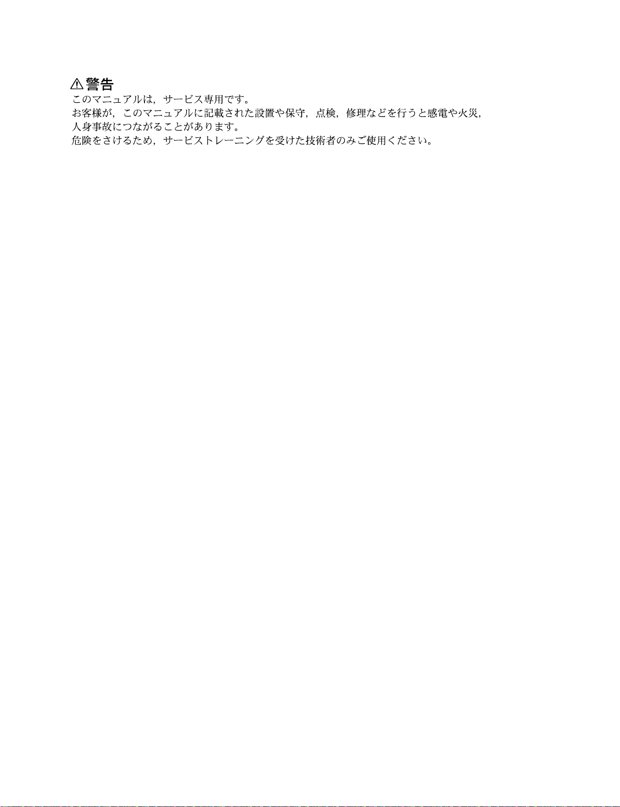
1-2-2. Power Cord
w
To avoid a fire or an electric shock, do not damage to the
power cord.
n
For the customer outside of the area as shown above or in a
part of Europe, the above-mentioned power cords can not
be used.
Use the power cord that is applicable to the places in the
world.
1
AC inlet
2
Power cord for the customer in the U.S.A. and Canada.
1Power cord set 1-557-377-11
2Plug holder (Black) 2-990-242-01
2
AC inlet
1
Power cord for the customer in the United Kingdom.
1DK-2401(UK) (approx. 2.4 m)
2Plug holder (Black) 2-990-242-01
Plug holder is included in DK-2401 (UK).
AC inlet
2
1
Power cord for the customer in Europe except the
United Kingdom.
1DK-2401 (AE) (approx. 2.4 m)
2Plug holder (Black) 2-990-242-01
Plug holder is included in DK-2401 (AE).

1-2 (E) DSM-T1
1-3. External Dimensions and Installation Space
To prevent the temperature rise inside the DSM-T1, pay careful attention to circulation of air in the place
where the DSM-T1 is installed.
The rear side of the DSM-T1 should be at least 10 cm (4 inches) away from walls for ventilation and
maintenance.
525
415.9 14
263.5
123.8
20.5 72.7
435
49
481
465
43.6
10
374
424
Mass : 8 kg (including two optional boards)
(Top view)
(Front view) (Right side view)
Unit : mm

1-3 (E)
DSM-T1
1-4. Matching Connectors and Cables
1-5. Input and Output Signal of Connector
1-4. Matching Connectors and Cables
When connecting cables to various connectors on the rear panel at the time of installing or servicing,
connect the following connectors/cables or their equivalents.
DSM-T1 Matching Connector/Cable
Panel indication Connector/cable Sony Part No.
REF IN BNC 75 Z, male 1-564-742-11
IF OUT 5C-2V cable*1
MONITOR
SPARE D-sub 25-pin, male 1-566-356-11 (Solderless type)
1-564-747-11 (Solder type)
*1 : It is recommended to use the coaxial cable 5C-2V of Fujikura America Inc./Fujikura Europe Ltd. (FEL) or the equivalent.
1-5. Input and Output Signal of Connector
1REF IN (BNCx1)
External reference video signal input (black burst or composite sync)
Sync level = 40 IRE/0.3 V p-p, 75 Z
2IF OUT (BNCx1)
Intermediate Frequency signal output
75 Z, 0/_10/_20 dBm (selectable), 70/140 MHz (selectable)
n
The level and frequency of the output can be selected from the menu.
For more information about the menu setting, refer to the Operation Manual.
3MONITOR (BNCx1)
Intermediate Frequency signal monitor output
75 Z, _10 dB as reference to the IF output level
4SPARE (D-sub 25-pin, Female)
For future use.
AC INBREAKER
SPARE
REF IN
IF OUT MONITOR
12
1
23
4

1-4 (E) DSM-T1
1-6. Internal Switches and Indicators
ENC-42 board
(A side/Component side)
m
.The addresses on the board are shown by ( ) marks.
.For the switches described “Factory use”, do not change
the factory settings.
[Switch]
S300 (G-5) :Factory use
n
Factory setting : S300-1 to 3: OFF
S300-4 : ON
(■indicates the switch lever position.)
S301 (F-5) : Factory use
n
Factory setting : All switch levers are set to OFF.
(■indicates the switch lever position.)
S1050 (A-11) : Reset switch
n
Do not press this switch under normal conditions.
S1051 (C-5) : Factory use
n
Factory setting : All switch levers are set to OFF.
(■indicates the switch lever position.)
1 2 3 4
ON
1 2 3 4
ON
ON
1 2 3 4 5 6 7 8
[Indicator]
D300 (G-6) (red) : Factory use
This indicator stays out under normal conditions.
D301 (G-6) (red) : Factory use
This indicator stays out under normal conditions.
D601 (P-9) (red) : PLL Lock indicator
Lights off when the PLL at 4 FSC (14.3 MHz) of the
internal clock locks with the selected reference signal.
(at 525 system)
D602 (P-10) (red) : PLL Lock indicator
Lights off when the PLL at 4 FSC (17.73 MHz) of the
internal clock locks with the selected reference signal.
(at 625 system)
D751 (N-6) (green) : PLL Lock indicator
Lights up when the PLL at 24.576 MHz of the internal
clock locks with the selected reference signal.
D754 (U-8) (red) : PLL Lock indicator
Lights off when the PLL at 27 MHz of the internal clock
locks with the selected reference signal.
D900 (E-6) (red) : PLL Lock indicator
Lights off when the PLL of the internal transmission
clock locks with the internal 27 MHz clock.
D901 (F-6) (red) : PLL Lock indicator
Lights off when the PLL of the internal information
clock locks with the internal 27 MHz clock.
D1051 (B-4) (green) : CPU Run indicator
Blinks during the CPU of the IC1052 (C-3) on the ENC-
42 board runs.
ABCDEFGHJ LMNPRST UK
1
2
3
4
5
6
7
8
9
10
11
S301 S300
D301 D300
D1051
S1051
D900 D901
S1050
D751
D601
D602
D754

1-5 (E)
DSM-T1
1-7. Rack Mounting
1-7. Rack Mounting
The DSM-T1 can be mounted in a 19-inch standard rack.
m
.If the DSM-T1 or the peripheral equipment are mounted
in a 19-inch standard rack, it is recommended to install a
ventilation fan to prevent a temperature rise in the rack.
Make sure that all the units in the rack should be
operated within the temperature range of 0 dC to 40 dC.
.Connect the enough long cables on the rear panel,
considering that the DSM-T1 is pulled out.
.To prevent falling the rack, fix it on the horizontal firm
floor with bolts.
Required parts
.Rack Mount Kit, RMM-30 (Option)
or
RACK-MOUNT SLIDES, Model 305A
Manufactured by Accuride
Slide length 558.8 mm (22 inch)
c
Be sure to use the specified rack mount rail.
If a rack mount rail other than the specified one is used, the
DSM-T1 may be dropped by insufficient strength of the
rack mount rail. This may cause a injury.
The following parts are supplied with the DSM-T1.
.Rack angle (1U) Assembly : 2 pcs.
.Rail bracket : 4 pcs.
.Screw (K 4x14) : 4 pcs.
.Screw (B 4x14) : 4 pcs.
.Screw (B 4x8) : 8 pcs.
.Screw (B 5x12) : 8 pcs.
.Screw (RK 5x14) : 4 pcs.
.Plate nut (small) : 4 pcs.
.Plate nut (large) : 4 pcs.
.Spring washer ø5 : 8 pcs.
.Washer ø5 : 8 pcs.
.Washer ø4 : 4 pcs.
.Ornamental washer : 4 pcs.
Procedures
1. Turn the power of the DSM-T1 off.
2. Remove the four feet from the bottom of the DSM-T1.
3. Attach the inner rails to the DSM-T1 using the screws
(K 4x14).
4. Attach the rack angle (1U) assemblies to the DSM-T1
using the screws (B 4x14) and washers (ø4).
Feet
Feet
B 3x10
B 3x10
Washers ø4
Washers ø4
Rack angle
(1U) assemblies
B 4x14
B 4x14
Inner rails
K 4x14
K 4x14

1-6 (E) DSM-T1
1-7. Rack Mounting
5. Attach the rail brackets to the outer rails temporarily
using the screws (B 4x8) and plate nuts (large).
6. Attach the outer rails to the rack using the screws
(B 5x12), washers (ø5), spring washers (ø5) and plate
nuts (small).
7. Adjust the rail brackets to specified position, then
tighten the screws secured temporarily in the step 5.
8. Install the DSM-T1 in the rack.
c
Be careful not to get caught your hand and finger in the
rack mount rail when installing the unit in the rack.
9. After installing the DSM-T1 in the rack, secure the
unit to the rack using the screws (RK 5x14) and
ornamental washers.
Inner rail The maximum traveling
distance : 580 mm
Outer rail
Rail bracket
Rack
The side installed
rack angle
Rail bracket Plate nut (large)
Outer rail
Spec. : 52
+5
mm
_0
Rack
B 4x8
B 5x12
Spring washer ø5
Washer ø5
Plate nut
(small)
Rack
Ornamental washers
RK 5x14
Ornamental washers
RK 5x14
n
When the DSM-T1 is mounted in a rack, the maximum
traveling distance is illustrated below.

1-7 (E)
DSM-T1
1-8. Optional Boards
Three varieties of the optional boards are available for the DSM-T1.
Installations are possible to a maximum of two boards according to your system.
SDDI Input Board BKSM-T101
When the BKSM-T101 is installed, the digital video and audio signals in SDDI format can be input in the
DSM-T1.
Digital Input Board BKSM-T102
When the BKSM-T102 is installed, the digital video signal in SDI format and the digital audio signal in
SDI format or AES/EBU format can be input in the DSM-T1.
Analog Input Board BKSM-T103
When the BKSM-T103 is installed, the analog composite video signal and the analog audio signals can be
input in the DSM-T1.
1-8. Optional Boards
4:2:2P
*2
ENC
*3
4:2:2P
*2
ENC
*3
A/D
DEC
*4
SDI
I/F
*1
SDDI
I/F
*1
A/D
MOD
*6
QPSK
*7
MUX
*5
IF OUT
DSM-T1
Digital Satellite Modulator
BKSM-T101
SDDI Input Board
BKSM-T102
Digital Input Board
BKSM-T103
Analog Input Board
Composite
4ch audio
SDI
w/4ch-audio
4ch AES/EBU
SDDI
*1 : Interface
*2 : MPEG2 4:2:2 P@ML
*3 : Encoder
*4 : Decoder
*5 : Multiplexer
*6 : Modulator
*7 : Quadrature Phase Shift Keying
Any two

1-8 (E) DSM-T1
Notes for installing
The optional board can be installed in either “1” (IN 1)
side or “2” (IN 2) side of the DSM-T1.
The installation position of the rear panel depends on the
optional board position.
When the board is installed in “1” side, install the rear
panel to the “1” side.
Similarly, when the board is installed in “2” side, install
the rear panel to the “2” side.
n
For more information about installation, refer to the
Installation Manual of each optional boards.
IN 2 side
IN 1 side
DSM-T1 Optional boards
IN 2 side
IN 1 side
1
2
1
2
1
2
1-9. Setting of Television System
Be sure to set the television system when the DSM-T1 is
installed.
To set the television system, select “03:VIDEO STD” in
the menu.
525/60 : 525/60 (NTSC) system
625/50 : 625/50 (PAL) system
n
For more details, refer to the Operation Manual.
1-8. Optional Boards
1-9. Setting of Television System

The material contained in this manual consists of
information that is the property of Sony Corporation and
is intended solely for use by the purchasers of the
equipment described in this manual.
Sony Corporation expressly prohibits the duplication of
any portion of this manual or the use thereof for any
purpose other than the operation or maintenance of the
equipment described in this manual without the express
written permission of Sony Corporation.
Le matériel contenu dans ce manuel consiste en
informations qui sont la propriété de Sony Corporation et
sont destinées exclusivement à l’usage des acquéreurs
de l’équipement décrit dans ce manuel.
Sony Corporation interdit formellement la copie de
quelque partie que ce soit de ce manuel ou son emploi
pour tout autre but que des opérations ou entretiens de
l’équipement à moins d’une permission écrite de Sony
Corporation.
Das in dieser Anleitung enthaltene Material besteht aus
Informationen, die Eigentum der Sony Corporation sind,
und ausschließlich zum Gebrauch durch den Käufer der
in dieser Anleitung beschriebenen Ausrüstung bestimmt
sind.
Die Sony Corporation untersagt ausdrücklich die
Vervielfältigung jeglicher Teile dieser Anleitung oder den
Gebrauch derselben für irgendeinen anderen Zweck als
die Bedienung oder Wartung der in dieser Anleitung
beschriebenen Ausrüstung ohne ausdrückliche
schriftliche Erlaubnis der Sony Corporation.

Printed in Japan
Sony Corporation 1998. 1 16
Broadcasting & Professional Systems Company ©1998
Published by Global Support Promotion Dept.
DSM-T1 (SY) J, E
3-200-066-01
Other manuals for DSM-T1
1
Table of contents
Other Sony Modulator manuals