Sony CF-CD73 User manual

SERVICE MANUAL
ICF-CD73
FM/AM CD PORTABLE RADIO
ICF-CD73V
TV/WEATHER/FM/AM
CD PORTABLE RADIO
US Model
ICF-CD73V
Canadian Model
AEP Model
UK Model
E Model
ICF-CD73
SPECIFICATIONS
ICF-CD73/CD73V
Ver. 1.4 2006.12
9-877-131-05 Sony Corporation
2006L05-1 Personal Audio Division
©2006.12 Published by Sony Techno Create Corporation
Model Name Using Similar Mechanism ZS-X3CP
CD Mechanism Type KSM-900AAA
Optical Pick-up Name KSS-900A
CD player section
System: Compact disc digitalaudiosystem
Laser diode properties: Material:GaAlAs
Wavelength: 780 nm
Emission duration: Continuous
Laser output:Less than 44.6 µW
(This outputis the value measured at a
distance of about 200 mmfrom the objective
lens surface on the opticalpick-upblock with
7 mm aperture.)
Frequencyresponse: 20 − 20 000 Hz
+1
−1.5
dB
Wow and flutter: Below measurable limit
Radio section
Frequencyrange: (ICF-CD73)
NorthAmerica
Band Channel
step
FM 87.5 −108 MHz 0.1 MHz
AM 530 −1 710 kHz 10 kHz
FM 87.5 −108 MHz 0.05 MHz
AM 531 −1 710 kHz 9 kHz
Other countries/regions
Band Channel
step
FM 87.5 −108 MHz 0.05 MHz
AM 531 −1 611 kHz 9 kHz
FM 87.5 −108 MHz 0.1 MHz
AM 530 −1 610 kHz 10 kHz
Frequency range: (ICF-CD73V)
Band Range Channel
step
TV 2 – 13 ch 1 channel
WEATHER 1 – 7 ch 1 channel
FM 87.5 – 108 MHz 0.1 MHz
AM 530 – 1 710 kHz 10 kHz
General
Time display:
NorthAmerica, UK: 12-hour system
Other countries/regions:24-hour system
Speaker: 50 mm (2 inches) dia, 6Ω
Poweroutputs:
400 mW+ 400 mW (at 10% harmonic
distortion)
Powerrequirements:
6 V DC, 4 R14 (size C) batteries
Externalpowersource: DC IN6 V
Dimensions:
Approx. 151.5 ×248 ×84 mm (w/h/d)
(Approx. 6 ×9
7
/
8
×3
3
/
8
inches) incl.
projecting parts and controls
Mass: Approx.1 350 g (2 lb16 oz) incl.batteries
Suppliedaccessories:
Suction cup (1), Strap (1)
AC poweradaptor (1)*
* Supplied with European model only
Design and specifications are subject to change
withoutnotice.
Photo: ICF-CD73V

2
ICF-CD73/CD73V
Using the AC power adaptor
•When operating the unit with an external power source, do not remove the
batteries.
These batteries serve to backup the clock and memory settings. Since the
batteries discharge in this case as well, we recommend changing them about
once a year.
•To prevent battery leakage, we recommend removing the batteries when the
unit is connected to a wall outlet.
•Before connecting and disconnecting the external power source plug, be
sure to turn off the radio/CD. Otherwise, “E ” may be displayed. When this
occurs,turn on the radio/CD so that “E ” disappears..
•When theAC power adaptor is not to be used for a long period of time,unplug
it both from the DC IN 6 V jack and from the wall outlet.
•When the cover of the DC IN 6 V jack is open (to use the AC power adap-
tor), the jack area is not splash-resistant. When the AC power adaptor is not
connected to the DC IN 6 V jack, be sure to close the cover of the DC IN 6
V jack.
•Use the recommended Sony AC poweradaptor * only. The polarity of the
plugs of other manufacturers may be different. Failure to use the recom-
mended AC power adaptor may cause the unit to malfunction.
*Supplied with European model only
If you have any questions or problems concerning your unit,please consult
your nearest Sony dealer.
About CD-Rs/CD-RWs
This unit is compatible with CD-Rs/CD-RWs but playback capability may vary
depending on the quality of the disc,the recording device and application soft-
ware.
ATTENTION AU COMPOSANT AYANT RAPPORT
À LA SÉCURITÉ!
LES COMPOSANTS IDENTIFIÉS PAR UNE MARQUE 0
SUR LES DIAGRAMMES SCHÉMATIQUES ET LA LISTE
DES PIÈCES SONT CRITIQUES POUR LA SÉCURITÉ
DE FONCTIONNEMENT. NE REMPLACER CES COM-
POSANTS QUE PAR DES PIÈCES SONY DONT LES
NUMÉROS SONT DONNÉS DANS CE MANUEL OU
DANS LES SUPPLÉMENTS PUBLIÉS PAR SONY.
SAFETY-RELATED COMPONENT WARNING!!
COMPONENTS IDENTIFIED BY MARK 0OR DOTTED
LINE WITH MARK 0ON THE SCHEMATIC DIAGRAMS
AND IN THE PARTS LIST ARE CRITICAL TO SAFE
OPERATION. REPLACE THESE COMPONENTS WITH
SONY PARTS WHOSE PART NUMBERS APPEAR AS
SHOWN IN THIS MANUAL OR IN SUPPLEMENTS PUB-
LISHED BY SONY.
Notes on chip component replacement
•Never reuse a disconnected chip component.
•Notice that the minus side of a tantalum capacitor may be dam-
aged by heat.
Flexible Circuit Board Repairing
•Keep the temperature of the soldering iron around 270 ˚C dur-
ing repairing.
•Do not touch the soldering iron on the same conductor of the
circuit board (within 3 times).
•Be careful not to apply force on the conductor when soldering
or unsoldering.
SAFETY CHECK-OUT
After correcting the original service problem, perform the follow-
ing safety check before releasing the set to the customer:
Check the antenna terminals, metal trim, “metallized” knobs,
screws, and all other exposed metal parts for AC leakage.
Check leakage as described below.
LEAKAGE TEST
The AC leakage from any exposed metal part to earth ground and
from all exposed metal parts to any exposed metal part having a
return to chassis, must not exceed 0.5 mA (500 microamperes).
Leakage current can be measured by any one of three methods.
1. A commercial leakage tester, such as the Simpson 229 or RCA
WT-540A. Follow the manufacturers’instructions to use these
instruments.
2. A battery-operatedAC milliammeter. The Data Precision 245
digital multimeter is suitable for this job.
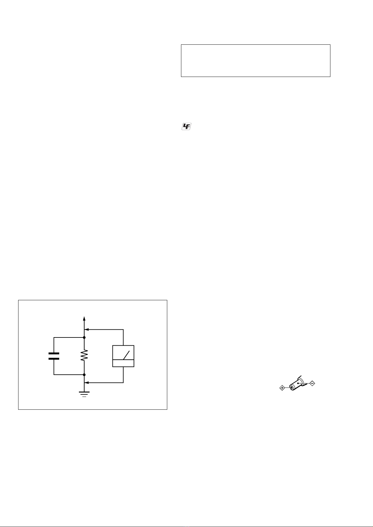
3. Measuring the voltage drop across a resistor by means of a
VOM or battery-operated AC voltmeter. The “limit” indica-
tion is 0.75 V, so analog meters must have an accurate low-
voltage scale. The Simpson 250 and Sanwa SH-63Trd are ex-
amples of a passive VOM that is suitable. Nearly all battery
operated digital multimeters that have a 2V AC range are suit-
able. (See Fig. A)
Fig. A. Using an AC voltmeter to check AC leakage.
1.5 k
Ω
0.15 µFAC
voltmeter
(0.75 V)
To Exposed Metal
Parts on Set
Earth Ground
CAUTION
Use of controls or adjustments or performance of procedures
other than those specified herein may result in hazardous ra-
diation exposure.
UNLEADED SOLDER
Boards requiring use of unleaded solder are printed with the lead-
free mark (LF) indicating the solder contains no lead.
(Caution: Some printed circuit boards may not come printed with
the lead free mark due to their particular size)
: LEAD FREE MARK
Unleaded solder has the following characteristics.
•Unleaded solder melts at a temperature about 40 ˚C higher than
ordinary solder.
Ordinary soldering irons can be used but the iron tip has to be
applied to the solder joint for a slightly longer time.
Soldering irons using a temperature regulator should be set to
about 350 ˚C.
Caution: The printed pattern (copper foil) may peel away if the
heated tip is applied for too long, so be careful!
•Strong viscosity
Unleaded solder is more viscou-s (sticky, less prone to flow)
than ordinary solder so use caution not to let solder bridges oc-
cur such as on IC pins, etc.
•Usable with ordinary solder
It is best to use only unleaded solder but unleaded solder may
also be added to ordinary solder.
Polarityoftheplug

3
ICF-CD73/CD73V
TABLE OF CONTENTS
1. SERVICING NOTES .............................................. 4
2. GENERAL .................................................................. 5
3. DISASSEMBLY
3-1. Disassembly Flow ........................................................... 6
3-2. Cabinet (Front) Section................................................... 6
3-3. Cabinet (Upper) Section ................................................. 7
3-4. Chassis (Main) Section ................................................... 7
3-5. LCD Board ...................................................................... 8
3-6. Mechanism Deck (KSM-900AAA) ................................ 8
3-7. Optical Pick-up (KSS-900A) .......................................... 9
3-8. Speaker (SP101)/(SP201) ............................................... 9
4. TEST MODE .............................................................. 10
5. ELECTRICAL ADJUSTMENTS........................ 13
6. DIAGRAMS
6-1. Block Diagram – CD Section – .................................... 17
6-2. Block Diagram – TUNER Section (ICF-CD73) – ....... 18
6-3. Block Diagram – TUNER Section (ICF-CD73V) – .... 19
6-4. Block Diagram – MAIN Section – ............................... 20
6-5. Note for Printed Wiring Boards and
Schematic Diagrams ....................................................... 21
6-6. Printed Wiring Board – CD Section – ......................... 22
6-7. Schematic Diagram – CD Section – ............................. 23
6-8. Printed Wiring Board
– TUNER Section (ICF-CD73) – .................................. 24
6-9. Schematic Diagram
– TUNER Section (ICF-CD73) – .................................. 25
6-10. Printed Wiring Board
– TUNER Section (ICF-CD73V) – ............................... 26
6-11. Schematic Diagram
– TUNER Section (ICF-CD73V) – ............................... 27
6-12. Printed Wiring Boards – MAIN Section – ................... 28
6-13. Schematic Diagram – MAIN Section –........................ 29
6-14. Printed Wiring Boards – POWER Section – ................ 30
6-15. Schematic Diagram – POWER Section – .................... 31
6-16. IC Pin Function Description .......................................... 34
7. EXPLODED VIEWS
7-1. Overall Section................................................................ 36
7-2. Cabinet (Front) Section................................................... 37
7-3. Cabinet (Main) Section ................................................... 38
7-4. Cabinet (Upper) Section ................................................. 39
7-5. Cabinet (Rear) Section-1 ................................................ 40
7-6. Cabinet (Rear) Section-2 ................................................ 41
7-7. Cabinet (Rear) Section-3 ................................................ 42
7-8. Optical Pick-up Section (KSM-900AAA) ..................... 43
8. ELECTRICAL PARTS LIST .............................. 44

4
ICF-CD73/CD73V
COLOR VARIATION
MODEL Destination Window Color Cabinet Color
Canadian CLEAR BLUE WHITE
ICF-CD73 Italian CLEARYELLOW BEIGE
UK
US (ORIGINAL) CLEAR BLUE WHITE
ICF-CD73V US (LIV) CLEAR BLUE WHITE
CLEARYELLOW BEIGE
The laser diode in the optical pick-up block may suffer electro-
static break-down because of the potential difference generated
by the charged electrostatic load, etc. on clothing and the human
body.
During repair, pay attention to electrostatic break-down and also
use the procedure in the printed matter which is included in the
repair parts.
The flexible board is easily damaged and should be handled with
care.
NOTES ON LASER DIODE EMISSION CHECK
The laser beam on this model is concentrated so as to be focused
on the disc reflective surface by the objective lens in the optical
pick-up block. Therefore, when checking the laser diode emis-
sion, observe from more than 30 cm away from the objective lens.
LASER DIODE AND FOCUS SEARCH OPERATION
CHECK
During normal operation of the equipment, emission of the laser
diode is prohibited unless the upper lid is closed while turning ON
the S701. (push switch type)
The following checking method for the laser diode is operable.
•Method
Emission of the laser diode is visually checked.
1. Open the lid.
2. Push the S551 as shown in Fig.1.
3. Press the [CD ] button.
4. Check the object lens for confirming normal emission of the
laser diode. If not emitting, there is a trouble in the automatic
power control circuit or the optical pick-up.
In this operation, the object lens will move up and down 2
times along with inward motion for the focus search.
SECTION 1
SERVICING NOTES
NOTES ON HANDLING THE OPTICAL PICK-UP
BLOCK OR BASE UNIT
S551
Fig.1 Method to push the S551
NX
ORIGINAL MODEL
WINDOW FrontView
LIV MODEL
DISCRIMINATION OF ORIGINAL AND LIV MODEL
There are two types of ICF-CD73V.
Refer to following.
Ver. 1.3
NOTES ON EXCHANGING THE FLEXIBLE FLAT
CABLE (13 CORE)
When the flexible flat cable which has connected the LCD board
(CNP402) and CD board (CNP702) is exchanged, please attach to
a set according to the following after bending.
1
Turn the character side up and bend in the direction
(back side) of A from an end in the position of about 9 mm.
back side
character side
character side
character side
2
Bend in the direction of B from an end in the position
of about 70 mm.
3
Attach in a set.
LCD board
(CNP402)
CD board
(CNP702
)
±
9mm
±
70 mm

5
ICF-CD73/CD73V
SECTION 2
GENERAL This section is extracted from
instruction manual.
5432
AUTO
OFF
VOLUME
TUNE/TIME SET
TIMER SET
MAX
MIN
TIMER
SET
ON/OFF
MODE
PRESETTUNING/PRESETTIMER
SELECT/ PRESET
CLOCK
1
RADIO CDSHUFFLE
REP1
MHz
kHz
AUTO OFF
TIMER
PRESET
TRACK
FM12PM
AM
ALL
RADIO
ON
BAND
OFF
CD
FM wireantenna
5432
AUTO
OFF
VOLUME
TUNE/TIME SET
TIMER SET
MAX
MIN
TIMER
SET
ON/OFF
MODE
PRESETTUNING/PRESETTIMER
SELECT/ PRESET
CLOCK
1
RADIO CD
SHUFFLE
REP1
MHz
kHz
AUTO OFF
TIMER
PRESET
TRACK
WEATHER
TV
FM12PM
AM
ALL
RADIO
ON
BAND
OFF
CD
FM wire antenna
ICF-CD73 ICF-CD73V
Setting the Clock
The displaywillflash “AM12:00” when the
batteries are installed or the AC power adaptor is
plugged in for the first time.
1Press and hold downCLOCK for more
than 2 seconds.
The beep sounds and the hour flashes in the
display.
2Rotate in either +/–directionthe TUNE/
TIME SET/TIMER SET dial until
correct hour appears in the display.
RADIO CD
SHUFFLE
REP1
MHz
kHz
AUTO OFF
TIMER
PRESET
TRACK
WEATHER
TV
FM12PM
AM
ALL
Each rotation of the dial changes the digit(s)
by one.
When you holdthe dial, the digit(s) change
rapidly.
3Press CLOCK .
The beep sounds and the minute starts to
flash. Repeat step 2 to set the minute.After
setting the minute, press CLOCK again. The
two beeps sound and the clock starts from
0 seconds.
RADIO CDSHUFFLE
REP1
MHz
kHz
AUTO OFF
TIMER
PRESET
TRACK
WEATHER
TV
FM12PM
AM
ALL
12-hour system: “AM 12:00” = midnight
24-hour system: “0:00” = midnight
Notes
•You can set the clock also duringthe radio
reception/CD playback mode.
•To set the current time quickly, rotate and hold
in either +/– direction the TUNE/TIME SET/
TIMER SETdial.
•To set the current time exactly, followstep 2
and press CLOCK again with the time signal of
a radio station.
the
Setting the Clock
The display will flash “AM12:00” when the
batteries are installed or the AC power adaptor
is plugged in for the first time.
1
Hold down CLOCK for more than
2 seconds.
The beep sounds and the hour flashes in the
display.
2
Rotate in either +/–direction the TUNE/
TIME SET/TIMER SET dial until the
correct hour appears in the display.
RADIO CD
SHUFFLE
REP1
MHz
kHz
AUTO OFF
TIMER
PRESET
TRACK
WEATHER
TV
FM12PM
AM
ALL
Each rotation of the dial changes the digit(s)
by one.
When you hold the dial, the digit(s) change
rapidly.
3
Press CLOCK .
The beep sounds and the minute starts to
flash. Repeat step 2 to set the minute. After
setting the minute, press CLOCK again. The
two beeps sound and the clock starts from
0 seconds.
RADIO CD
SHUFFLE
REP1
MHz
kHz
AUTO OFF
TIMER
PRESET
TRACK
WEATHER
TV
FM12PM
AM
ALL
12-hour system: “AM 12:00” = midnight
“PM 12:00” = noon
Notes
•You can set the clock also during the radio
reception/CD playback mode.
•To set the current time quickly, rotate and hold
in either +/– direction the TUNE/TIME SET/
TIMER SET dial.
•To set the current time exactly, follow step 2
and press CLOCK again with the time signal of
a radio station.

6
ICF-CD73/CD73V
• This set can be disassembled in the order shown below.
SECTION 3
DISASSEMBLY
Note: Follow the disassembly procedure in the numerical order given.
3-2. CABINET (FRONT) SECTION
3-1. DISASSEMBLY FLOW
5
two screws
(2.6
×
10)
6
4
two screws
(2.6
×
10)
9
screw (2.6
×
8)
0
SW board block
qa
cabinet (front) section
3
five screws
(2.6
×
10)
1
Open the buckle
(battery case lid).
2
Open the
battery case lid.
7
flat cable (CNP704)
8
connector
(CNP302)
3-2. CABINET (FRONT) SECTION
(Page 6)
3-3. CABINET (UPPER) SECTION
(Page 7) 3-8. SPEAKER (SP101)/(SP201)
(Page 9)
3-6. MECHANISM DECK
(KSM-900AAA)
(Page 8)
3-5. LCD BOARD
(Page 8)
3-7. OPTICAL PICK-UP
(KSS-900A)
(Page 9)
SET
3-4. CHASSIS (MAIN) SECTION
(Page 7)

7
ICF-CD73/CD73V
3-3. CABINET (UPPER) SECTION
3-4. CHASSIS (MAIN) SECTION
3
two screws
(2.6
×
8)
4
two claws
5
cabinet (upper) section
2
connector
(CNP602)
1
connector
(CNP601
)
1
flat cable
(CNP702)
2
connector
(CNP303)
3
two screws
(2.6
×
8)
5
two screws
(2.6
×
8)
6
two screws
(2.6
×
8)
9
chassis (main) section
8
Remove the solder
of FM lead wire antenna
(ANT1).
7
cabinet (front) section
4
CD board

8
ICF-CD73/CD73V
3-5. LCD BOARD
3-6. MECHANISM DECK
(KSM-900AAA)
3
two screws
(2.6
×
8)
5
three tapping
screws
6
chassis CD block
9
rubber (vibration)
0
mechanism deck
(KSM900AAA)
8
rubber
(vibration)
7
rubber
(vibration)
1
flexible board
(CNP705)
2
connector
(CNP706)
4
relay board
3
screw
(2.6
×
8)
4
LCD board
1
two flat cables
(CNP401, 402)
2
connector
(CNP1: CD73)/
(CNP2: CD73V
)

9
ICF-CD73/CD73V
3-8. SPEAKER (SP101)/(SP201)
3-7. OPTICAL PICK-UP
(KSS-900A)
3
gear (B) (780C)
2
holder (780C)
1
screw
(2
×
8)
7
sled screw assy (780E)
5
rack spring (780C)
4
screw
(B1.7
×
4)
8
optical pick-u
p
(KSS-900A)
6
4
spacer (slit)
1
connector
(CNP304)
5
two speakers
(SP101, SP201)
3
bracket (SP)
ditch ditch
Note: When installing the speaker lead wire,
lead the speaker lead wire along ditche
s
and bosses of the cabinet (front).
ditch
cabinet (front)
boss
boss
3
bracket (SP)
2
screw (2.6
×
8)
2
screw (2.6
×
8)

10
ICF-CD73/CD73V SECTION 4
TEST MODE
RADIO CD
SHUFFLE
REP1
MHz
kHz
AUTO OFF
TIMER
PRESET
TRACK
WEATHER
TV
FM12PM
AM
ALL
LCD AND KEY TEST MODE
Procedure:
1. Turn the power on while pressing simultaneously three but-
tons of [RADIO ON BAND], [CLOCK], and [1].
2. The microcomputer version will be displayed on the LCD.
3. Press the [AUTO OFF] button. (The LCD display will become
as follows)
LCD display
4. BEEP (A) will be output and the display corresponding to a
button is turned off, if a button on the set is pressed. Also,
BEEP (A) is output when the button is released.
Button CorrespondingTable
Button Segment
CLOCK AM, PM, : (colon),
TIMER SET ON/OFF TIMER , AUTO OFF
11b, 1c
22a, 2b, 2d, 2e, 2g
33a, 3b, 3c, 3d, 3g
44b, 4c, 4f, 4g
55a, 5c, 5d, 5f, 5g
TUNE – .6a, 6b, 6c, 6d, 6e, 6f, 6g
TUNE + >TRACK , PRESET
RADIO ON BAND RADIO, WEATHER, TV, FM,
1(FM), 2(FM), TV, .(point), MHz,
kHz
OFF xBatteryLow, 1a, 1d, 1e, 1f, 1g, 1h, 1i,
2c, 2f, 2h, 2i, 3e, 3f, 4a, 4d, 4e, 5b,
5e
CD NX CD, Pz1, Pz2, Pz3, Pz4
MODE , SHUFFLE, REP, 1, ALL
5. After all buttons on the set were pressed, press the [AUTO
OFF] button, and BEEP (B) will be output and the test mode
will be terminated.
6. If there is even one button that was not accepted, the set will
not bereleased from test mode even though the [AUTO OFF]
button is pressed.
7. The set will return to normal state when the LCD AND KEY
TEST MODE is terminated.

11
ICF-CD73/CD73V
CD TEST MODE
Procedure:
1. Connect 47 kΩand 100 kΩresistors in parallel to the end of S501 on the LCD board, and short another end of resistors to the GND,
and the CD TEST MODE will be activated.
2. Insert a CD disc.
3. Turn the power on. Press the [CD ] button.
LCD display
4. The following shows the state transition table for each button operation in respective sub modes of CD TEST MODE.
StateTransitionTable
If each button is pressed in respective sub modes, the mode will transit to the sub modes listed in table.
Mode transits to sub modes listed in table, if a button is pressed in respective sub modes.
5. Turn the power off to release the CD TEST MODE.
CD
MODE Explanation LCD Button
MAIN SUB
OFF CD –+RADIO ON AUTO OFF –+Processing
BAND end
Long pressed
INT State when TEST MODE is activated.
00 STOP0 FOCUS0
STOP STOP0 State when a button is pressed once from initial state.
01 FOCUS0 STOP STOP EF Normal SLDF SLDR
STOP0 Automatically adjusted value is held.
02 STOP0 FOCUS0 Normal SLDF SLDR
FOCUS FOCUS0 AUTO FOCUS transfer mode
03 STOP FOCUS
FOCUS FOCUS SERVO ON state.(CLV-S, TRK/SLED, SERVO OFF)
04 STOP F.LPC EF AUTO FCSF FCSR
It will be referred to as LPC ON if FOCUS carries out on.
OFF
F.LPC OFF LPC OFF in FOCUS state.
05 STOP ALSV FOCUS FOCUS FOCUS0 FCSF FCSR
ALL ALSV State where all servo systems are turned on.
07 STOP ALPC OFF FOCUS FOCUS EF AUTO FCSF FCSR
SERVO ALPC OFF State where all servo systems are turned on.(LPC:OFF)
08 STOP TGUP FOCUS FOCUS FCSF FCSR
TGUP State with TRK GAIN UP in all servo systems are turned on.(LPC:ON)
09 STOP ALSV FOCUS FOCUS FCSF FCSR
AUTO Mode in which automatic adjustment is made at once.
b
SLED SLDF SLED is fed outward in STOP state.
cSTOPSTOPSTOPSTOP SLDF
SLDR SLED is fed inward in STOP state.
dSTOPSTOPSTOPSTOP SLDR
F.SLED FCSF SLED is fed outward in FOCUS state.
E FOCUS FOCUS FOCUS FOCUS FCSF
FCSR SLED is fed inward in FOCUS state.
F FOCUS FOCUS FOCUS FOCUS FCSR
.
>
.
>
NX
x
NX

12
ICF-CD73/CD73V
CD-JUMP TEST MODE
Procedure:
1. Connect the oscilloscope to TP (TE) and TP (VC) on the CD board.
Connecting Location: CD board (See page 16)
2. Connect 47 kΩand 100 kΩresistors in parallel to the end of S501 on the LCD board, and further connect 100 kΩand 220 kΩresistors
respectively and short them to the GND, and the CD-JUMP TEST MODE will be activated.
3. Insert a CD disc.
4. Turn the power on. Press the [CD ] button.
LCD display
5 . If the [MODE] button is pressed, you can jump in fast feed or fast reverse direction with the + >or – .button by the jump
amount set in Table 1.
Table 1
LCD Button
+ >– .
REP ALL TRACK + 1 TRACK - 1
SHUFFLE TRACK + 10 TRACK - 10
SHUFFLE, REP TRACK + 100 TRACK - 100
Waveform of TP (TE) and TP (VC) output in each mode is as follows.
6. Turn the power off to release the CD-JUMP TEST MODE.
CD
TRACK
NX
REP ALL mode
500 µs/div
SHUFFLE mode
1 ms/div
SHUFFLE REP mode
10 ms/div

13
ICF-CD73/CD73V
AM IF ADJUSTMENT
Adjust for a maximum reading on level meter
T1 450 kHz
( ): ICF-CD73V
AM VCO VOLTAGE ADJUSTMENT
Adjustment Part Frequency Display Reading on Digital Voltmeter
L4 (L6) 530 kHz (531 kHz) 1.0 ±0.05 V (1.0 ±0.1 V)
Confirmation 1,710 kHz 5.3 ±0.7 V
( ): ICF-CD73V
AM TRACKING ADJUSTMENT
Adjust for a maximum reading on level meter
L3 (L5) 620 kHz (580 kHz)
CT3 (CT5) 1,400 kHz (1,490 kHz)
FM IF ADJUSTMENT
Adjust for a minimum reading on level meter
T2 10.7 MHz
FM VCO VOLTAGE ADJUSTMENT (ICF-CD73)
Adjustment Part Frequency Display Reading on Digital Voltmeter
L2 108 MHz 3.0 ±0.2 V
Confirmation 87.5 MHz 1.3 ±0.3 V
FM TRACKING ADJUSTMENT (ICF-CD73)
Adjust for a maximum reading on level meter
L1 87.5 MHz
CT1 108 MHz
FM/TV (2 – 6 CH) VCO VOLTAGE ADJUSTMENT (ICF-CD73V)
Adjustment Part Frequency Display Reading on Digital Voltmeter
L4 TV 2 ch 1.0 ±0.15 V
CT3 108 MHz 4.0 ±0.15 V
FM/TV (2 – 6 CH) TRACKING ADJUSTMENT (ICF-CD73V)
Adjust for a maximum reading on level meter
L2 TV 2 ch
Confirmation 108 MHz
TV (7 – 13 CH)/WEATHER (1 – 7 CH) VCO VOLTAGE ADJUSTMENT (ICF-CD73V)
Adjustment Part Frequency Display Reading on Digital Voltmeter
L3 WEATHER 2 ch 1.0 ±0.15 V
CT4 TV 13 ch 4.1 ±0.15 V
TV (7 – 13 CH)/WEATHER (1 – 7 CH) TRACKING ADJUSTMENT (ICF-CD73V)
Adjust for a maximum reading on level meter
L1 WEATHER 2 ch
CT2 TV 13 ch
Adjustment and Connecting Location:TUNER board (ICF-
CD73)
(See page 14)
TUNER board (ICF-
CD73V)
(See page 15)
TUNER SECTION 0 dB=1 µV
[AM]
Setting:
Function: RADIO
Band: AM
[FM/TV/WEATHER]
Setting:
Function: RADIO
Band: FM (ICF-CD73)
FM/TV/WEATHER (ICF-CD73V)
•Repeat the procedures in each adjustment several times, and the
tracking adjustments should be finally done by the trimmer ca-
pacitors.
•Remove FM/TV/WEATHER antenna in FM/TV/WEATHER
adjustment.
AM RF signal
generator
30% amplitude
modulation by
400 Hz signal
Output level:
as low as possible
Put the lead-wire
antenna close to
the set.
+
–
level meter
set
3.2 Ω
JACK board
CNP304 pin 2
JACK board
CNP304 pin 1
FM RF signal
generator
75 kHz frequency
deviation by 1 kHz
signal
Output level:
as low as possible
+
–
level meter
JACK board
CNP304 pin 2
JACK board
CNP304 pin 1
set
3.2 Ω
0.01 µF
TUNER board
TP (GND)
TUNER board
TP (ANT)
digital voltmete
r
TP (VT)
TP (GND)
100 kΩ
TUNER board
SECTION 5
ELECTRICAL ADJUSTMENTS

14
ICF-CD73/CD73V
Adjustment and Connecting Location:
TP
(VT)
TP
(GND)
TP
(ANT)
–TUNER BOARD (Component Side) (ICF-CD73) –
–TUNER BOARD (Conductor Side) (ICF-CD73) –
L4
AM VCO Voltage Adjustment
L2
FM VCO Voltage Adjustment
AM Tracking Adjustment CT3
L3
FM Tracking Adjustment
T1 AM IF Adjustment
T2 FM IF Adjustment
L1
CT1

15
ICF-CD73/CD73V
Adjustment and Connecting Location:
T2
IF Adjustment
T1
IF Adjustment
L6
AM VCO Voltage Adjustment
L2
CT1
CT2
L1
FM/TV (2 – 6 CH)
Tracking Adjustment
AM Tracking Adjustment
L3
CT4
L4
CT3
L5
CT5
TV (7 – 13 CH)/
WEATHER (1 – 7 CH)
Tracking Adjustment
TV (7 – 13 CH)/
WEATHER (1 – 7 CH)
VCO Voltage Adjustment
TV TV (2 – 6 CH)
VCO Voltage Adjustment
–TUNER BOARD (Component Side) (ICF-CD73V) –
–TUNER BOARD (Conductor Side) (ICF-CD73V) –
TP
(GND
)
TP
(
VT
)
TP
(
ANT
)

16
ICF-CD73/CD73V
CD SECTION
Perform all CD section check in the test mode.
FOCUS BIAS CHECK
Procedure:
1. Connect the oscilloscope to TP (RF) and TP (VC) on the CD
board.
2. Set the CD test mode. (Refer to CD TEST MODE (See page
11))
3. Insert the test disc (YEDS-18). (Part No. 3-702-101-01) (CD)
4. Press the [CD ] button. (LPC ON)
5. Confirm that the oscilloscope waveform is as shown in the
figure below. (eye pattern)
A good eye pattern means that the diamond shape (◊) in the
center of the waveform can be clearly distinguished.
6. Press the [CD ] button. (LPC OFF)
7. Perform confirmation in the same manner as step 5.
8. Press the [OFF ] button.
9. Change the test disc (TCD-W082L). (Part No. J-2502-063-2)
(CD-RW)
10. Perform confirmation in the same manner as step 4 to 7.
• RF signal reference waveform (eye pattern)
Connecting Location:
VOLT/DIV: 0.2 V (with the 10: 1 probe in use.)
TIME/DIV: 500 ns
CD:
1.1 ±0.2 Vp-p (LPC ON)
1.1 ±0.3 Vp-p (LPC OFF)
CD-RW:
1.0 ±0.2 Vp-p (LPC ON)
0.9 ±0.3 Vp-p (LPC OFF)
When observing the eye pattern, set the oscilloscope
for AC range and raise vertical sensitivity.
TP
(VC)
TP
(RF)
IC702
IC701
– CD BOARD (Conductor Side) –
TP
(TE)
x
NX
NX

ICF-CD73/CD73V
1717
SECTION 6
DIAGRAMS
6-1. BLOCK DIAGRAM – CD Section –
A
B
D
F
E
C
I-V AMP
DETECTOR
19
20
17
18
22 SL+
SL–
FCS–
FCS+
TRK+
TRK–
SPINDLE
MOTOR DRIVE
M702
(SPINDLE)
SLED
MOTOR DRIVE
23
M701
(SLED)
FOCUS
COIL DRIVE
TRACKING
COIL DRIVE
SP+
SP– 7
8
9
10
FCS IN
TRK IN
SL IN
SP IN
FOCUS/TRACKING COIL DRIVE,
SPINDLE/SLED MOTOR DRIVE,
POWER CONTROL
IC702
LD
PD
LASER DIODE
OPTICAL PICK-UP
BLOCK
(KSM-900AAA)
2-AXIS
DEVICE
(FOCUS)
(TRACKING)
25
24
REGB
M
M
4MUTE34
AUTOMATIC
POWER
CONTROL
Q701
8FIN2 (PD1)
7FIN1 (PD2)
+
MIX 4
RF
LPF
EQ
PH
BH
10 TIN2 (F)
9TIN1 (E)
A/D
SW
LPF
TRACK
JUMP
TBAL
80 LDD APC
AUDIO
ADJUST
SERVO
PROCESSOR
RUPTURE
DETECT
79
LDS
SW
AGC
D/A
13
FE
15
TE
20
TDO
21
FDO
23
SLDO
22
SPDO
S/H
3EFMIN SLISE LEVEL
CONTROL
ERROR
CORRECTION
AUDIO CD
RAM
8FS
DIGITAL
FILTER
INTERPOLATION
MUTE
ATTENUATION
DEEMPHASIS
1 BIT
DAC
42
LCHO
RCHO
LPF
DOUT
AUDIO
OUT
FSEQ
PLL
VCEC
CLV, CAV
CONTROL FRAME SYNC
DETECT,
PROTECT, INSERT,
EFM DECODE
31
RAM
DRF 67
25
CONT4
72
CONT1
66
RES
65
WRQ
61
CE
62
CL
63
DI
64
DO
RF AMP, FOCUS/TRACKING SERVO,
DIGITAL SIGNAL PROCESSOR, CLV SERVO,
DIGITAL FILTER, D/A CONVERTER
IC701
53 CD DATA IN
54 CD DATA
55 CD CLK
56 CD CE
50 WRQ
58 XRST
57 DRF
39 FSEQ
59 CD ON
61
CD OPEN
S551
(CD LID OPEN/CLOSE)
A
SYSTEM
CONTROLLER
IC401
(1/2)
R-CH
GENERAL PURPOSE
PORTS
COMMAND
INTERFACE
DRF
5MUTE1
XOUT
XIN
X701
16.9344MHz
CD LCH
PD1
PD2
F
E
LO LD
LO PD
TRK +
TRK –
FCS +
FCS –
When the optical pick-up
is inner position
ON :
S701
(LIMIT)
45
39
CLOCK
GENERATOR
48
49
• SIGNAL PATH
: CD PLAY
• R-ch is omitted due to same as L-ch.
MUTING
SWITCH
Q702
DC IN CD ON
SWITCH
Q703, 704
REGULATOR 30
+3.3V
REGULATOR
Q705
CD +3.3V PVCC
31
(Page 20)

ICF-CD73/CD73V
1818
6-2. BLOCK DIAGRAM – TUNER Section (ICF-CD73) –
2
24
4 7
20 21
FM
RF AMP
FM
MIX
FM
OSC
FM IF
AMP
IF
BUFFER
AF
BUFFER
AF
AMP MPX MUTE
STEREO/
MONO,
FM/AM
AM IF
AMP
FM
DET
AM
DET
6
FM
RF IN
22 AM
RF AMP
AM
MIX
AM
RF IN
MIX OUT
OSC
OUT
CF2
FM/AM PLL
IC2
CF4
FM
RF OUT
10
QUAD
FM
IF IN 12
15
11
L-OUT
MPX
IN
R-OUT
13
AM
IF IN
LPF1/BAND
AM OSC
FM OSC
FM/AM RF AMP, MIX, OSC,
FM/AM IF AMP, DET, MPX
IC1
L2
FM VCO VOLTAGE
L4
AM VCO VOLTAGE
CT1, L1
FM TRACKING
CT3, L3
AM TRACKING
T1
AM IFT
LOW-PASS
FILTER
LOW-PASS
FILTER
• SIGNAL PATH
: FM
: AM
X1
75kHz
CT3
L1
FM RF
XOUT
XIN
AMIN
IF IN
ST-IND
LP-OUT
LP-IN
FMIN
20
19
111218
FM/AM
6
CT1
D1
L4
AM OSC
L2
FM OSC
LEVEL
DET
ST
IND
14
LPF2/MO-ST
AM
OSC BUFFER
BUFFER
SWALLOW
COUNTER
UNIVERSAL
COUNTER
CCB
INTERFACE
REFERENCE
DIVIDER
UNLOCK
DETECT
12 BIT
PROGRAMMABLE
DIVIDER
PHASE
DETECTOR/
CHARGE PUMP
SHIFT REGISTER & LATCH
1/2
BAND
DI
CL
CE
DO
DET
OUT
ANT1
FM LEAD WIRE
ANTENNA
PD
IF OUT
ST IND
2
3
1
4
10 9
BAND
7
MO/ST
13817 16
17 18
16
19
D2
D3
(1/2)
D3
(2/2)
T1
AM IF
• R-ch is omitted due to same as L-ch.
PLL DATA
PLL CLK
PLL CE
COUNT
R-CH
(Page 20)
C
MUTE
TU LCH
(Page 20)
B
T2
FM IFT
T2
FM IF
L3
AM FERRITE-ROD
ANTENNA
VT B+
PLL DATA, PLL CLK,
PLL CE, COUNT, MUTE

ICF-CD73/CD73V
1919
6-3. BLOCK DIAGRAM – TUNER Section (ICF-CD73V) –
24
4 7
20 21
FM
OSC
FM IF
AMP
IF
BUFFER
AF
BUFFER
AF
AMP MPX MUTE
STEREO/
MONO,
FM/AM
AM IF
AMP
FM
DET
AM
DET
6
FM
RF IN
22 AM
RF AMP
AM
MIX
AM
RF IN
MIX OUT
OSC
OUT
CF2
FM/AM PLL
IC2
CF4
FM
RF OUT
10
QUAD
FM
IF IN 12
15
11
L-OUT
MPX
IN
R-OUT
13
AM
IF IN
LPF1/BAND
AM OSC
FM OSC
FM/AM RF AMP, MIX, OSC,
FM/AM IF AMP, DET, MPX
IC1
T1
AM IFT
LOW-PASS
FILTER
X1
75kHz
XOUT
XIN
AMIN
IF IN
ST-IND
LP-OUT
LP-IN
FMIN
20
19
1112186
LEVEL
DET
ST
IND
14
LPF2/MO-ST
AM
OSC BUFFER
BUFFER
SWALLOW
COUNTER
UNIVERSAL
COUNTER
CCB
INTERFACE
REFERENCE
DIVIDER
UNLOCK
DETECT
12 BIT
PROGRAMMABLE
DIVIDER
PHASE
DETECTOR/
CHARGE PUMP
SHIFT REGISTER & LATCH
1/2
FM/AM
DI
CL
CE
DO
DET
OUT
PD
IF OUT
ST IND
2
3
1
4
10 9
TV-H
5 13817 16
17 18
16
T1
AM IF
PLL DATA
PLL CLK
PLL CE
COUNT
R-CH
(Page 20)
C
MUTE
TU LCH
(Page 20)
B
T2
FM IFT
T2
FM IF
PLL DATA, PLL CLK,
PLL CE, COUNT, MUTE
• SIGNAL PATH
: FM/TV (2
–
6CH)
: AM
• R-ch is omitted due to same as L-ch.
: TV (7
–
13CH)/WEATHER
TV-H/WB
MO/ST
7
FM/TV-L
D1
ANT1
FM/TV/WEATHER
LEAD WIRE ANTENNA
B.P.F.
BPF1
D13
D15
L1
TV/WEATHER
RF
CT2
D14
L2
FM/TV
RF
RADIO 6V
D2
D17 L3
TV/WEATHER
OSC
CT4
D24 L4
FM/TV
OSC
CT3
RADIO B+
RADIO B+
TV (7-13CH)/
WEATHER
ON SWITCH
Q11
RADIO B+
FM/TV (2-6CH)
ON SWITCH
Q12
RADIO B+
SWITCHING
Q13
D21
OSC
BUFFER
Q14
2FM
RF AMP
FM
MIX
CT2, L1
L2
FM/TV(2 – 6CH)
TRACKING
TV(7 – 13CH)/WEATHER
TRACKING
CT5, L5
AM TRACKING
CT5 D3
(1/2)
L5
AM FERRITE-ROD
ANTENNA
L6
AM VCO VOLTAGE
L6
AM OSC
D3
(2/2)
CT4, L3
CT3, L4
FM/TV(2 – 6CH)
VCO VOLTAGE
TV(7 – 13CH)/WEATHER
VCO VOLTAGE
19
VT B+
LOW-PASS
FILTER

ICF-CD73/CD73V
2020
6-4. BLOCK DIAGRAM – MAIN Section –
: CD PLAY
: TUNER (FM/AM)
76RESET
32R ON
31POWER ON
SYSTEM CONTROLLER
IC401 (2/2)
B+ SWITCH
Q302, 303
DRY BATTERY
SIZE “C”
(IEC DESIGNATION R14)
4PCS. 6V
+3.3V
REGULATOR
IC403
RESET SIGNAL
GENERATOR
IC402
DC IN 6V
J901
–+
PVCC
UCOM B+
POWER
AMP B+
VT B+
41AC IN
AUDIO
CIRCUIT
B+
R-CH
LINE AMP
Q153
D101
•R-ch is omitted due to same as L-ch.
•SIGNAL PATH
R-CH
R-CH
R-CH
MUTING
Q101
LINE AMP
Q152
TU LCH
B
ICF-CD73
(Page 18)
CD LCH
A
(Page 17)
R DATA
R CLK
R CE
COUNT
66
65
64
63
ICF-CD73
(Page 18)
C
MUTE
62
SEG0 – SEG17
LIQUID CRYSTAL DISPLAY
LCD401
10 – 27
COM0 – COM3
6 – 9
PLL DATA
PLL CLK
PLL CE
COUNT
MUTE
A MUTE
78 79
+ +
POWER AMP
IC303
71
BUZZER
52
PLL DATA, PLL CLK,
PLL CE, COUNT, MUTE
WAKE UP
SWITCH
Q401
KEY 2
S607 – 611
44
KEY 1
S601 – 606
45
KEY0
S501 – 503
46
KEY CHK
51
7071
X401
32.768kHz
7475
X402
4.19MHz
XT1
XT2
X1
X2
D308
D401
DC MIDDLE VOLTAGE
CONTROL SWITCH
Q405
AGC
Q154
AGC CONTROL
SWITCH
Q301
D309
FILTER AMP
Q151
RV601
VOLUME
MUTING
CONTROL SWITCH
Q403
LIN LOUT
+
R-CH
SP101
(L-CH)
SP201
(R-CH)
+6V
REGULATOR
Q301, 306, 307
42VM
80BATT CHK M
49DC CHK
LOAD
43VH
DC/DC
CONVERTER
Q304, 305, T301
+3.3V
REGULATOR
IC301
D402
LOAD CONTROL
SWITCH
Q406
77
ICF-CD73V
(Page 19)
ICF-CD73V
(Page 19)
B MUTE
This manual suits for next models
1
Table of contents
Other Sony Portable Radio manuals

Sony
Sony ICF-703 User manual

Sony
Sony ICF-M60LRDS User manual

Sony
Sony ICF-CD73 User manual

Sony
Sony Shower Mate ICF-S79 User manual

Sony
Sony ICF-B01 User manual

Sony
Sony ICF-SW7600GR - Portable Radio User manual

Sony
Sony Walkman SRF-H4 User manual

Sony
Sony CRF-150 User manual

Sony
Sony Walkman ICF-S10MK2 User manual

Sony
Sony ICF-CD73W User manual