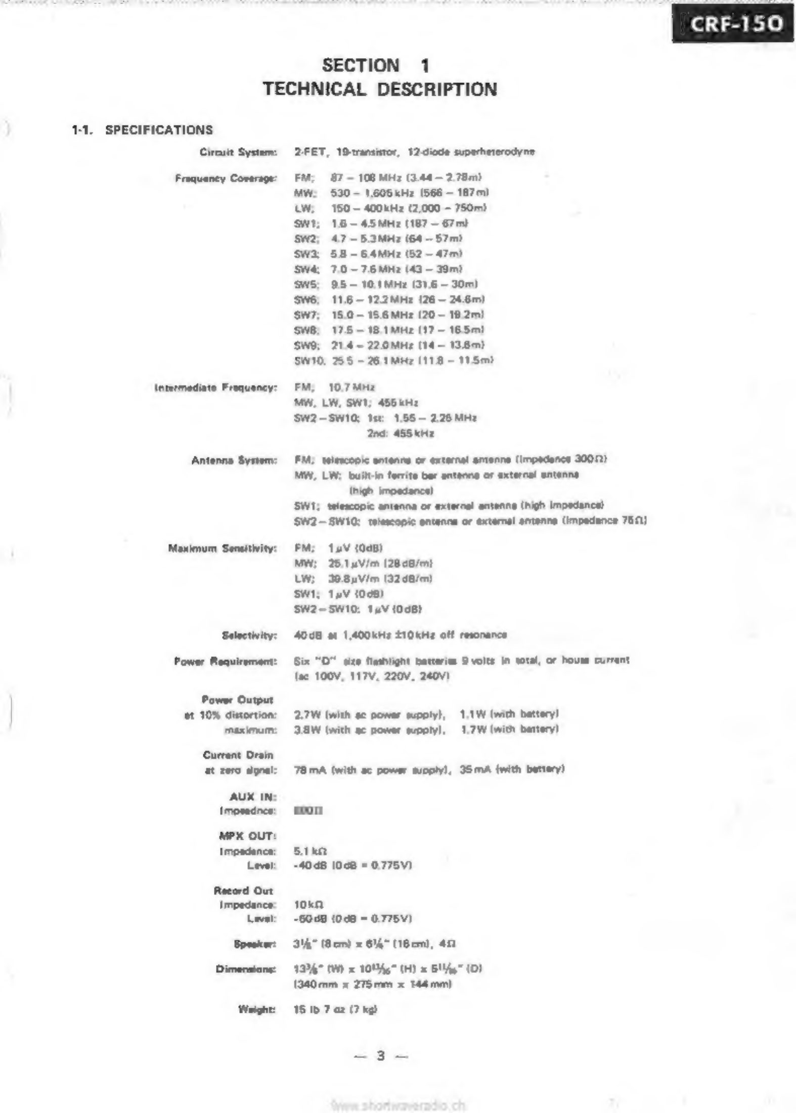
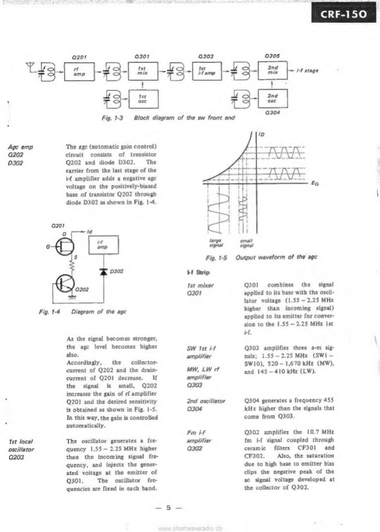
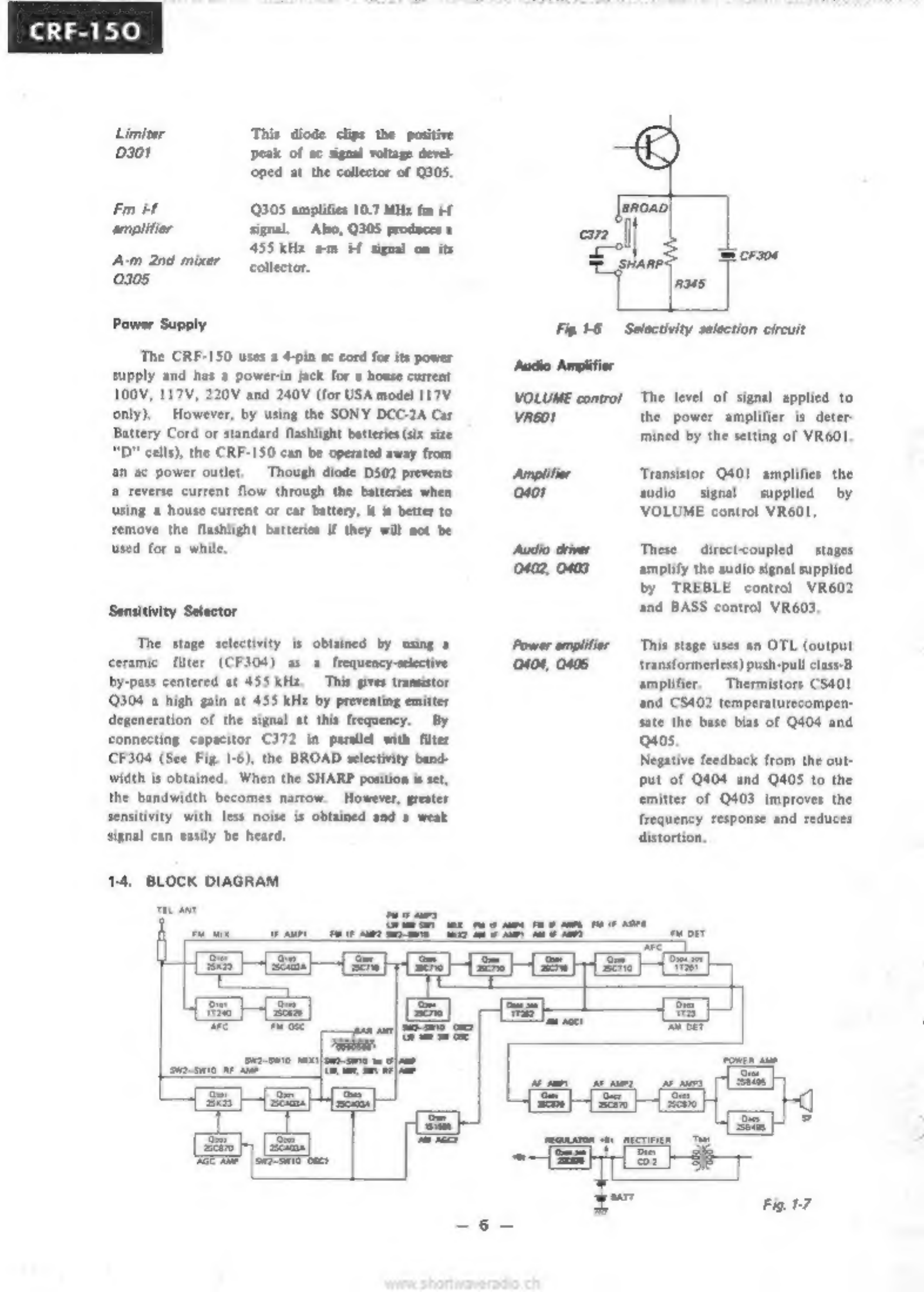
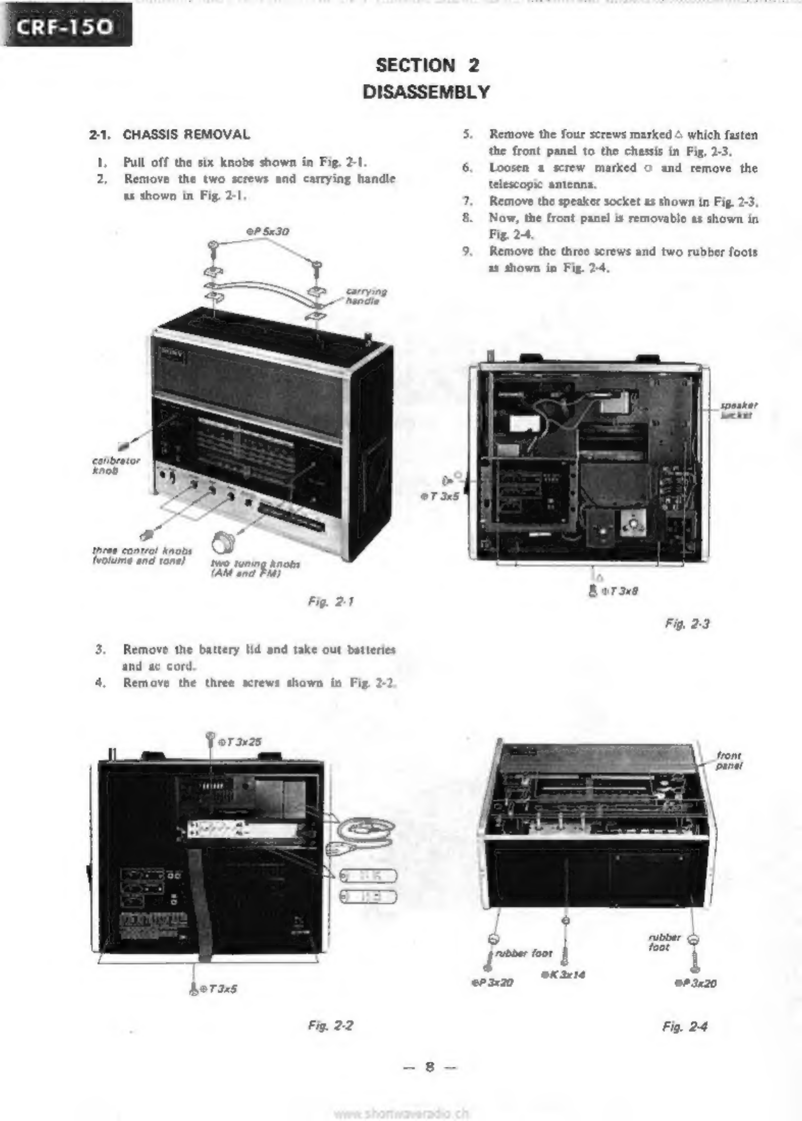
Sony CRF-150 User manual

ЧЕН
FM/AM
13-BAND
PORTABLE
RADIO
SONY.
SERVICE
MANUAL

‚Section
TABLE
OF
CONTENTS
Title
TECHNICAL
DESCRIPTION
.
1-1.
Specifications
.
Technical
Features
13.
Circuit
Description.
14.
Block
Diagram
1-5.
External
View
1-6.
Major
Parts
Location
DISASSEMBLY
mes
d
2-1,
Chas
Removal.
8
22.
Fm
Tuner
Removal
°
23.
Sw
Tuner
Removal
8
9
24
ср/М
Circuit
B.
Removal
........
10
2-5
Power
Supply
Circuit
Board
Removal
n
2-6.
Af
Circuit
Board
Removal
"
"
2-7.
Dial
Scale,
Dial
Drum
Removal
and
Reassembly
n
24.
Dial
Cord
Restringing
.
n
ADJUSTMENT
PROCEDURES...
14
3-1.
Hf
Alignment
-
,
14
3-2.
Frequency
Coverage
and
Tracking
Adjustment
15
3-3.
Adjusting
Parts
Locations
..
18
3-4.
Voltage
and
Current
Adjustment
19
SCHEMATIC
AND
MOUNTING
DIAGRAMS
20
4-1.
Schematic
Diagram
20
4-2.
Fm
Tuner
Circuit
Board
..............
23
43.
SW2-SW10
Front
End
PNE
4-4.
Cp/if
Circuit
Board
_.
28
4-5.
Af
Circuit
Board...
»
4-6.
Power
Circuit
Board
E
47.
Jack
Panel
эз
4-8.
Wiring
Diagram
35
ELECTRICAL
PARTS
LIST
.....
37
PACKING
AND
EXPLODED
VIEW
........
42
61.
Packing
_
3
42
6-2.
Exploded
View
43

SONY.
SERVICE
MANUAL
SUPPLEMENT
SErrewoen,
1970
Subject:
1.
Troubleshooting
guide
USA
model
31,800
02718
ааа
and
lat
GENERAL
EXPORT
“
}
|
model
42,420
J
1.
TROUBLESHOOTING
GUIDE
Trouble
|
Band
Symptom
Сане
Remedy
No
sound
|
mw
1)08V
or
higher
|
1)
Leaky
tuning
1)
Apply
20У
de
between
(Af
circuit
at
the
emitter
of
|
capacitor
the
rotor
and
the
stator
normal
but
0304.
(06
to
of
the
tuning
capacitor
to
no
sound
07
V
in
normal)
Produce
а
spark
from
speaker.)
2)
№
sound
even
|
2)
Defective
bar
antenna
|
2)
Replace
the
сой.
и
"the
bar
|
сой
antenna
сой
is
adjusted
3)
Collector
voltage
|
3)
Internal
resistance
of
|
3)
Replace
the
tuning
meter
at
Q306
is
too
|
—
the
tuning
meteris
too
low.
(2.75V
is
|
high
normal)
Sw2-10
|
No
sound
at
the
|
Shorted
padding
capac
|
Replace
these
capacitors
high-frequency
end
|
itor.
(C247,
C250,
of
each
band
C256,
C259,
C262
Normalsoundatthe
|
C268,
C271)
low-frequency
end
Low
FM
Noise
heard
during
|
Antenna
lead
(coaxial
|
Resolder
the
lead
sensitivity
reception
cable)
of
tuner
touches
the
tuner
case.
sui
Great
difference
in
|
Yellow
lead
of
the
switch
|
Resolder
the
ead.
noise
level
be:
|
is
connected
to
ground.
tween
SHARP
and
BROAD
positions
of
the
SELECTIV
TTY
switch
sw2-10
|
Noise
heard
all
over
|
3.8
to
4.1V
at
the
emit-
|
Adjust
R369
for
45V.
the
SW
bands.
ter
of
Q309.
(45У
is
normal)
Shock
FM
1)
Shock
noise
1)
Shield
plate
touching
|
1)
Separate
the
shield
plate
noise
the
CP
printed
circuit
|
from
the
printed
circuit
,
board board
2)
Shock
noise.
2)
Leads
of
capacitors
|
2)
Cover
the
legs
of these
mounted
on
the
сот
|
capacitors
with
plastic
ductor
side
are
touch
|
tubing.
ing
the
legs
of
IFT
uw
1)
Shock
noise.
1)
Loose
contact
in
the
|
1)
Replace
the
switch
pilot
lamp
switch.
2)
Shock
noise
2)
Loose
nut
on
the
EXT
|
2)
Tighten
mut,
then
secure
ANT
terminal
with
contact
cement
=
4
=

Trouble
Band
Symptom
Cause
Remedy
Oscillation
|
FM
1)
Oscillating
noise
|
1)
Coupling
between
|
1)
Separate
1319
from
1319
and
СЕЗІ.
CF301
2)
Oscillating
noise
|
2)
°S”
curve
is
too
|
2)Lower
the
curve
sharply
adjusted
level
3)
Oscillating
noise
|
3)
Leads
from
the
tuner
|
3)
Separate
the
leads
from
and
antenna
to
5301-2
|
the
printed
circuit
board.
disturb
te
if
stage.
Tuning
FM
Pointer
does
not
|
Leaky
G77
between
|
Replace
C377.
meter
move.
IFT
F301
and
5301-8.
MW
Minimum
pointer
|
R313
misadjusted.
Readjust
R313
for
0.25
to
movement.
028V
at
the
emitter
of
0303.
Wrong
FM
1)
Pointer
docs
mot
aide
|
1)
Make
the
pointer
side
dal
properly.
more
smoothly.
pone
2)
Incorrect
frequency
|
2)
Readjust
the
frequency
indication
pem
w.
Mw
T)
Incorrect
frequency
|
1)
Readjust
the
frequency
coverage.
coverage.
2)
Backlash
2)
Loose
screw
on
the
|
2)
Engage
gears,
and
tighten
double
gear.
the
screw.
sw2-10
1)
Loose
core
in
the
first
|
1)
Fix
the
core
with
an
oscillator
сой.
elastic
band,
or
replace
the
coil
2)
Normal
when
|
2)
Damaged
second
oscil-
|
2)
Replace
the
сой.
the
core
of
the
|
Шогсой.
second
oscillator
coil
is
pulled
ош.
Unstable
392-16
|
1)
No
reception
|
D
Faulty
or
beni
жаза
|
1)
Repair
or
straighten
the
reception
when
the
band
|
іп
the
turret
tuner.
|
contact
selector
is
turned
counterclockwise.
Normal
тесер.
tion
when
these-
lector
is
ішпей
clockwise.
2)
Reception
okay
|
2)
Imperfect
solder
joint.
|
2)
Resolder
the
defective
joint.
Battery
cur-
|
АШ
‘Shorted
0502.
Replace
0502
rent
flows
voltage
at
any
point
when
ac
in
the
circuit.
power
sup-
ply
isop-
erating.
Reverse
Lw
Connect
the
cut
foil
with
operation
on
the
low
fre
|
CF302
and
CF303
is
cut.
|
a
jumper
lead.
of
the
quency
range.
SELECTIV-
ITY
switch.
FM
tuning
|
FM
Tight
dial
Defective
gear
Deepen
gear
teeth,
and
shaft
gear
apply
lubricating
oil
skips.

CRF-150
SECTION
1
TECHNICAL
DESCRIPTION
1-1.
SPECIFICATIONS
Circuit
System:
2-FET,
1Stransistor,
12diode
superheterodyne
Frequency
Coverage:
FM;
87
-
108
MHz
(344
—
278m)
1,605
kHz
(566
—
187m)
LW;
150
—
400kHz
(2,000
—
750m)
SWI;
18—45MHz
(187
—
67m)
-5змн:
(64
—
57m)
SW3:
58-64MMz
(52
-
47m)
SW&
7.0
~7.6MMz
(43
-
39m)
SWS;
95
-
10.1
MHz
(31.6
—
30m)
116
=
12.2MHz
(26
—
24.6)
15.0
—
156мнг
(20—
192m)
175
-
18.1
MHz
(17
—
165m)
SW;
214-
220MM:
(14
—
136m)
SW10;
255
-
26.1Mkz
(118
-
115m}
Intermediate
Frequency:
FM:
10.7
MHz
MW,
LW,
SWI;
456
KHz
SW2—SW10;
Ist:
1.55
-
225
МН
‘nd:
ASS
kHz
Antenna
System:
FM;
telescopic
antenna
or
external
antenna
(impedance
3002)
MW,
LW;
built-in
ferrite
bar
antenna
or
external
antenna
(nigh
impedance)
50:
telescopic
antenna
or
external
antenna
(high
impedance)
‘SW2—SW10;
telescopic
antenna
or
external
antenna
(impedance
752)
FM;
тыу
(0881
MW;
25.12
V/m
(2848/m)
LW;
39.84V/m
(3248/m)
SWI;
тыу
(048)
SW2-SWIO:
14V
(048)
Selectivity:
—
4098
at
1400kHz
HOkHz
off
resonance
Power
Requirement:
Six
"О"
size
flashlight
batterie
9
volts
in
total,
or
house
current
(ae
100V,
117V,
220V,
240V)
'ower
Output
st
10%
distortion:
2.7W
(with
ac
power
supply),
1.1W
(with
battery)
maximum:
38W
(with
ac
power
supply),
1.7W
(with
battery)
Current
Drain
at
zero
signal:
78mA
(with
ac
power
supply),
35
mA
(with
battery)
soon
saka
-4одв
(048
=
0776У)
тоқа
-6048
(048
=
0.775V)
Speaker:
3747
(Bem)
x
614"
(16em,
هه
Dimensions:
1334"
(W)
x
10!%e"
(H)
x
S14”
(D)
(340mm
x
275mm
x
144mm)
Weight:
15
Ib
7
oz
(79)

150
1-2.
TECHNICAL
FEATURES
*
High-performance
portable
radio
receiver
with
thirteen
bands;
FM,
MW,
LW,
SWI-SWIO.
*
FET
(field
effect
transistor)
with
tripletuned
passive
input
circuit
for
superior
interference
rejection.
*
High-sensitivity
and
selectivity
on
SW
bands
using
double-superheterodyne
front
end.
*
High-fidelity
af
amplifier
with
OTL
circuit.
*
Choice
of
three
power
sources;
house
current,
battery,
car
battery.
1:3.
CIRCUIT
DESCRIPTION
Stage/control
Function
Fm
Tuner
FET
mixer
Usually
an
fm
front
end
consists
ото!
of
an
rf
amplifier,
mixer
and
local
oscillator
as
shown
in
Fig.
I1.
The
rf
amplifier
sometimes
worsens
the
crossmodulation
handling
ability
of
the
receiver
when
ordinary
bipolar
transistors
are
used,
It
is,
however,
diffi
cult
to
eliminate
the
rf
amplifier
because
its
removal
causes
strong
spurious
radiation,
poor
sensi-
tivity,
and
а
poor
noise
figure.
To
solve
this
problem,
the
Model
Fig.
1-1
Usual
fm
front
end
Fig.
12
CRF-150
fm
front
end
Local
oscillator
0102
Afc
diode
D101
Fm
Ы
amplifier
0103
CRF-150
uses
a
low-noise
junc-
tion
FET
for
the
mixer
and
a
triple-tuned
passive
input
circuit
as
shown
in
Fig.
1-2.
The
Model
CRF-150
is
capable
of
clear
fm
reception
even
in
strong
signal-
strength
areas
due
to
the
extremely
superior
interference-
rejection
characteristics
of
the
passive
input
circuit,
The
oscillator
generates
a
fre-
quency
10.7
MHz
higher
than
the
incoming
signal
frequency
and
injects
the
generated
voltage.
at
the
source
of
FET
mixer
0101.
This
diode
is
connected
across
the
resonant
circuit
of
the
oscil-
lator
and
works
as
a
variable-
capacitance
diode.
А
dc
feed
back
voltage
from
the
discri
nator
controls
the
bias
applied
to
the
diode
to
keep
the
local
oscillator.
frequency
correct.
Transistor
Q103
amplifies
the
10.7
MHz
i-f
signal
produced
by
mixer
0101
and
coupled
to
it
through
Hf
transformer
IFT
101.
A
block
diagram
of
the
sw
front
end
is
shown
in
Fig.
1-3.
Such
an
arrangement
effectively
sup-
presses
image
signals,
since
the
high
value
of
the
first
i4
causes
the
desired
and
image
signals
to
differ
greatly
in
frequency.
At
the
same
time,
the
relatively
low
value
of
the
second
if
makes
it
possible
to
obtain
high
amplifi-
cation
as
well
as
sharp
discrimi-
mation
against
signals
differing
only
slightly
in
frequency
from
the
desired
signal.
The
result
is
that
this
double-
superheterodyne
front
end
pro-
vides
a
combination
of
greater
image
suppression
and
higher
adjacent
channel-selectivity
than
can
be
realized
in
a
simple
super-
heterodyne
receiver.

if
stage
سأ
чае
у
ESE
Fig.
1:3
Block
diagram
of
the
sw
front
end
Age
amp
‘The
age
(automatic
gain
control)
0202
Circuit
consists
of
transistor
0302
Q202
and
diode
0302.
The
carrier
from
the
last
stage
of
the
if
amplifier
adds
a
negative
арс
voltage
on
the
positively-biased
base
of
transistor
Q202
through
diode
D302
as
shown
in
Fig.
1-4.
озо!
В
0
m
Me,
mal
6
ome
07
gal
d
Fig.
1-5
Output
waveform
of
the
age
ud
M
Strip
P
Ist
mixer
Q301
combines
the
signal
озо!
applied
to
its
base
with
the
oscil-
—
lator
voltage
(1.55
-
2.25
MHz
higher
than
incoming
signal)
applied
to
its
emitter
for
conver
sion
to
the
1.55
—
2.25
MHz
Ist
Fig.
1-4
Diagram
of
the
age
Аз
the
signal
becomes
stronger,
Е
the age
level
becomes
higher
SW
tst
м
0303
amplifies
three
am
sig-
sito:
amplifier.
mals;
1.55
2.25
MHz
(SWI
—
decortindy;
the;
collier
SWIO),
$20
—
1,670
kHz
(MW),
current
of
Q202
and
the
drain-
MW,
LW
rf
254 145
410
kB
(LW):
current
of
0201
decrease.
If
amplifier
the
signal
is
small,
0202
0303
increases
the
gain
of
rf
amplifier
Q201
and
the
desired
sensitivity
2nd
oscillator
0304
generates
a
frequency
455
is
obtained
as
shown
in
Fig.
1-5.
0304
kHz
higher
than
the
signals
that
In
this
way,
the
gain
is
controlled
come
from
0303.
automatically.
Fm
if
Q302
amplifies
the
10.7
MHz
1st
focal
‘The
oscillator
generates
a
fre-
amplifier
fm
if
signal
coupled
through
quency
1.55
—
2.25
MHz
higher
0302
ceramic
filters
CF301
and
than
the
incoming
signal
fre-
CF302.
Also,
the
saturation
quency,
and
injects
the
gener-
due
to
high
base
to
emitter
bias
ated
voltage
at
the
emitter
of
clips
the
negative
peak
of
the
Q301.
Тһе
oscillator
fre-
ac
signal
voltage
developed
at
quencies
are
fixed
in
each
band.
the
collector
of
Q302.

CRF-150
Limiter
This
diode
clips
the
positive
D301
Peak
of
ac
signal
voltage
devel
oped
at
the
collector
of
0305.
Fm
if
0305
amplifies
10.7
MHz
fm
+f
amplifier.
signal,
Also,
0305
produces
a
455
kHz
am
Ы
signal
on
its
Am
2nd
mixer
conector,
0305
Power
Supply
Fig
16
Selectivity
selection
circuit
Тһе
CRF-150
uses
a
4-pin
ac
cord
for
its
power
Bs
Asi
supply
and
has
a
powerin
jack
for
a
house
current
100V,
117V,
220V
and
240V
(for
USA
model
117V
VOLUME
control
The
level
of
signal
applied
to
only).
However,
by
using
the
SONY
DCC-2A
Car
VR601
the
power
amplifier
is
deter-
tery
Cord
or
standard
flashlight
batteries
(six
size
mined
by
the
setting
of
VR601.
"D"
cells),
the
CRF-150
can
be
operated
away
from
ап
ас
power
outlet.
Though
diode
0502
prevents
Amplifier
‘Transistor
Q401
amplifies
the
а
reverse
current
flow
through
the
batteries
when
0401
audio
signal
supplied
by
using
а
house
current
or
car
battery,
it
is
better
to
VOLUME
control
VR601.
remove
the
flashlight
batteries
if
they
will
not
be
used
for
a
while,
Audio
driver
These
direct-coupled
stages
0402,
0403
amplify
the
audio
signal
supplied
by
TREBLE
control
VR602
and
BASS
control
VR603,
Sensitivity
Selector
‘The
stage
selectivity
is
obtained
by
using
a
Power
amplifier
This
stage
uses
an
OTL
(output
ceramic
filter
(CF304)
as
а
frequency-selective
0404,
0406
transformerless)
push-pull
class-B
by-pass
centered
at
455
kHz.
This
gives
transistor
amplifier,
Thermistors
CS401
Q304
a
high
gain
at
455
kHz
by
preventing
emitter
and
CS402
temperaturecompen-
degeneration
of
the
signal
at
this
frequency.
Ву
sate
the
base
bias
of
Q404
and
connecting
capacitor
C372
in
parallel
with
filter
0405.
СЕЗ04
(See
Fig.
1-6),
the
BROAD
selectivity
band-
Negative
feedback
from
the
out-
width
is
obtained.
When
the
SHARP
position
is
set,
put
of
0404
and
0405
to
the
the
bandwidth
becomes
narrow.
However,
greater
emitter
of
0403
improves
the
sensitivity
with
less
noise
is
obtained
and
a
weak
frequency
response
and
reduces
signal
can
easily
be
heard,
distortion,
1-4.
BLOCK
DIAGRAM
е
Fig
17

CRF-150
EXTERNAL
VIEW
3419372.
andis,
carrying.
383391].
emblem
"Sony
3835842.
knob,
calibrator
—|
ning
meter
ob
rz
y,
dial
tuning
1607-16913
Jack,
earphone’
56:
—
Bar
A»
band
selector
1514-50311
тмин)
witch,
power
knob,
selectivity
Fig.
1:8
MAJOR
PARTS
LOCATION
—
—
1502241
‘speaker
401-38-23
ant
сой,
mwlw
ferrite
bar
Y38519.11
fm
tuner
block
Y-3871201-1
3833895-
sw
tuner
block
escutcheon,
SW2-SWIO
Bond
selector
152616511
voltage
selector.
153926411
BE
printed
circuit
board,
1614304:
Power
supply.
Hide
switch
15026212
|
d
1
180936211
printed
circuit
board,
Connector,
ext
Eolit
d
power
supply
144153612
transformer,
power.
X3813806.
_
Jack
panel
агу
Fig.
1-9

СВЕ-150
SECTION
2
DISASSEMBLY
21.
CHASSIS
REMOVAL
1,
Pull
off the
six
knobs
shown
in
Fig.
2-1
2,
Remove
the
two
screws
and
carrying
handle
as
shown
in
Fig.
2-1
2
calibrator
1
~
i
ЖА
a
8
trotume
and
tone)
wo
tuning
knots
(ate
and
EM)
Fig.
2-1
3.
Remove
the
battery
lid
and
take
out
batteries
and
ac
cord.
4,
Remove
the
three
screws
shown
in
Fig.
2-2
Fig.
22
Remove
the
four
screws
marked
4
which
fasten
the
front
panel
to
the
chassis
in
Fig.
23.
Loosen
a
screw
marked
o
and
remove
the
telescopic
antenna.
Remove
the
speaker
socket
as
shown
in
Fig.
2-3,
Now,
the
front
panel
is
removable
as
shown
in
Fig.
24.
Remove
the
three
screws
and
two
rubber
foots
as
shown
in
Fig.
2-4
speaker
Socket
Fig.
23
3x20
27.2420
Fig.
24

10.
Loosen
the
three
screws
and
pull
off the
sw
жайым
band
selector
knob
as
shown
in
Fig.
2-5.
11.
Now,
the
chassis
is
removable
as
shown
in
Fig.
2:6.
unsoider
2g
26x4
йор
[Гон
shron
serow
|
ers
ПЕС
selector
|
23.
SW
TUNER
REMOVAL
1.
Remove
the
chassis.
2.
Unsolder
the
ten
lead
wires
shown
in
Fig.
2-8.
two
coaxial
cables
pvc
wire
RM
/
tuning
capacitor
rounding
leads
22.
FM
TUNER
REMOVAL
*
|.
Remove
the
chassis.
2.
Remove
the
seven
screws
marked
Fig.
2-7.
3.
Remove
the
two
screws
marked
ж.
4.
Remove
the
screw
marked
O.
5.
Unsolder
the
two
soldered
portions
on
the
shield
cover
marked
c.
6,
Take
out
the
shield
cover
and
fm
tuner
circuit
board
as
illustrated
in
Fig.
2-7.
Fig,
28
nd
A
in

СВЕ-150
24.
Remove
the
five
screws
and
the
shield
cover
as
shown
in
Fig.
2-9
and
unsolder
the
two
lead
Loosen
the
four
screws
marked
Now,
sw
tuner
block
is
removable
in
the
direc-
tion
shown
by
the
arrow.
Рабка
Fig,
29
СРЛЕ
CIRCUIT
BOARD
REMOVAL
Unsolder
the
same
ten
lead
wires
in
Fig
2-8
as
sw
tuner
removal,
Unsolder
the
six
lead
wires
at
ferrite
bar
antenna
as
shown
in
Fig.
2-10.
Fig.
210
T
зем
cover
Remove
the
four
screws
at
the
jack
panel
as
ülustrated
in
Fig.
2-10
and
unsolder
the
six
lead
wires
shown
in
Fig.
2-11
Remove
the
three
screws
shown
in
Fi
Unsolder
the
three
lead
wires.
Loosen
the
four
lead
wires
from
the
lead
wire
holding
lug.
Slide
off
the
CP-IF
circuit
board
in
the
direc-
tion
shown
by
the
arrow
in
Fig,
2-12.
coaxial
coaxial
coaxial
SR
GAY”
ых
Fig,
211
lend
wire
holding
lug.
Fig.
212

25.
27.
POWER
SUPPLY
CIRCUIT
BOARD
REMOVAL
Remove
the
two
screws
shown
in
Fig.
2-13.
Turn
the
circuit
board
in
the
direction
shown
by
the
arrow.
Fig.
213
AF
CIRCUIT
BOARD
REMOVAL
Remove
the
four
screws
shown
in
Fig.
2-14.
Remove
the
circuit
board
in
the
direction
shown
by
the
arrow.
Fig.
214
DIAL
SCALE
AND
DIAL
DRUM
REMOVAL
Remove
the
chassis.
Remove
the
four
screws
shown
in
Fig.
2-15
Release
the
pointers
from
dial
cords.
=й
=
CRF-150
>
Da
‘pointer
dia
scale
Fig.
215
Remove
the
dial
scale.
5.
Remove
the
drum
holder
A
by
removing
the
two
screws
marked
Ó
in
Fig.
2-16,
6.
Release
the
two
screws
marked
©
in
Fig.
2-16,
7.
Pull
the
dial
drum
towards
you.
Fig.
216
Dial
Drum
Reassembly
1.
Turn
the
sw
band
selector
so
that
the
osc
coil
which
has
the
minimum
turns
comes
to
the
vertical
position
as
shown
in
Fig.
2-16.
2.
Attach
the
dial
drum
to
the
drum
holders
setting
the
two
screws
marked
Oin
Fig.
2-16.
3.
Set the
dial
scale.
4.
Turn
the
dial
drum
so
that
the
drum
indicates
SWIO
and
the
distance
between
the
dial
scale
and
the
line
on
the
drum
becomes
544
inches
(2mm)
as
shown
in
Fig.
2-15.
Fasten
the
two
screws
marked
*
in
Fig.
2-16.

4.
Rotate
the
driving
pulley
for
am
fully
clock-
28.
DIAL
CORD
RESTRINGING
wise
to
its
minimum
capacitance
position
as
shown
in
Fig.
2-19,
5.
Rotate
the
driving
pulley
for
fm
band
fully
counterclockwise
to
its
minimum
capacitance
position
as
shown
in
Fig,
2-20.
Preparation
1.
Remove
the
chassis
2.
Remove
the
four
screws
shown
in
Fig.
2
and
take
out
the
dial
scale,
3.
Remove
the
volume
holder
by
removing
the
two
screws
as
shown
in
Fig.
2-18,
/
а»
таз
m"
imum
шашы,
жш
1,
pulmo-
7
P
_®
9.
=
=
зни
|
иш»
Сы
|
шу
5
jean
тат
/
8236.04.
x38236.04.
7
18236.
==
Wann
C
v
Fig.
2.19
-12-

2.
Fm
Tuning
Capacitor
Driving
Cord
3824-162.
"б
762312032
Goring,
dial
cord
سدح
>
3811-140
driving
pulley;
at
fully
counterclockwise
position
‘pulley,
P40
363385042
Shatt,
fm
tuning
à
Td
ume
Va"
(15mm)
Fig.
2-20
3.
Pointer
Setting
dil
cord
for
am
driving
pulley:
at
fully
(counterclockwise
position)
pointer
setting
—ponnon
pointer
setti
9
D
yellow
tine
[d
on
pointer
та
line
A
‘on
pointer
(driving
pulley:
at
fully
counterclockwise
position]
Fig.
221
=

31.
IF
ALIGNMENT
Test
Equipment/Tools
Required:
10.7
MHz
Sweep
Generator
Rf
signal
generator
(for
fm
and
a-m)
Oscilloscope
утум
Loop
antenna
Screw
driver
for
alignment
SECTION
3
ADJUSTMENT
PROCEDURES
1.
FM
IF
ALIGNMENT
Preparation:
Band
selector:
FM
AFC;
OFF
Selectivity:
SHARP
Local/DX:
DX
Sweep
Sweep
Generator
Generator
|
Adjust
Remarks
Coupling
Frequency
سنا
—
IFT
F101
|
Adjust
for
maximum
amplitude
at
IFT
F301
|
and
symmetrical
"S"
curve
on
кам
10.7
MHz
|
MPX
OUT
jack
|
IFT
F302
|
the
scope.
(See
Fig.
3-2)
(See
Fig.
3-1)
ШЕГЕ
Е
IFT
F304
|
Ant.
Switch:
EXT.
АМТ.
s
Fig.
3-1
Fm
if
alignment
setup
Fig.32
“S”
curve
on
oscilloscope
‘ext,
ant
terminal
TF
oon)
2.
AM
IF
ALIGNMENT
Preparation:
Band
selector:
MW
‘Tuning
Capacitor:
minimum
capacitance
position
Rf Rf
Sit
|
|
Mie
|
mmm
|
уш
|
де
ВЕ
Coupling
Frequency
|
gom
|
ЫЛ
|
SO
|
птш
|
лана
Tor
manen
nawa
(See
Fig.
3-3.)
am
modulated)
jack
T
+
Fig.
33
Ат
if
alignment,
MW/LW
frequency
coverage
and
tracking
adjustment
setup
dé

32.
FREQUENCY
COVERAGE
AND
TRACKING
ADJUSTMENT
Preparation:
VTVM
Connection:
To
MPX
OUT
jack
Modulation:
FM
.....
400
Hz
+22.SkHz
frequency-modulated
signal
АМ...
1
kHz
30%
amplitude-modulated
signal
AFC:
OFF
Selectivit
SHARP
тєш
|W
Sarat]
meme
Adam
|
биш»
|
Sencar
E
adun
mm
Goes
|
ey
|
w
m
[rr
|
ss
|
pn”
ғы
ni
سه
|
(Жалы
Lg
x
Ant
Switch:
EXT
puo
far
Soon
LL
|
Seis,
|
sam
|
اه
стз
Mn
Rt
mal
ғы
The
қосы
vom
equipment
терімі
Ter
ie
дани
теме
maker
s
sty
a
factory
anne.
Fully
MW
osc
coil
ee
a
A
pu
pon
—
|
mm
=
=
с
—
вы
Seletar
MW
antenna
ма
ю
1304-1
Adjust
for
maximum
meter
620 kHz 620 kHz
^
rem
Mo
rf
cll
na
mw
ы
1308
ыы
Tram
ТІ
Teen
|
Мет
ieu
|
dade
|
Баха
signal
CT305
mm
тыу
LW
oe
col
тыу
TW
ox
viet
mm
m
E
TW
ant
con]
Band
Selector:
LW
E
—
ditto
—
оюн
Tune
to
Adjust
for
maximum
meter
i
ою:
|
sten
m.
Тәке
TV
an
inner
To
EE
sus
380kHz
LW
rf
trimmer
азе
тш
SW
өкесі
swt
ESS
MER
left
d
L311
беюну
does
Tuy
|
391 om
inner
омен
|
Pr
сто
Band
Selector:
Si
as
Е
ms
сөй
Unsolder
a
blue
lead
shown
mns
|
teus
Leitz
|
swi
ef
col
Re
Lior
Мин
fo
maman
ret
эп
теше
жұтыла
|
"ist
Tume
to
E
«um
42MHz
‘SWI
rf
trimmer
см
=
e

pem
Dial
Ado
Remarks
Seti
ғау
SW1-SWIO,
2nd
кї
ox
сой
1310
To
the
base
SW2-SWI0,
2nd
of
озо!
225
Mite
ad
ES
ж
ок
trimmer
CT307
|
Band
Selector:
SW2
capacitor
Tune
م
|
SW2-SWIO,
Adjust
for
maximum
meter
ФВ
доғ
|
16ыш
16мш
|
Ist
Hf
ой
reading,
An
IF
See
Fig.
3-7
Soa
130%,
139€
Tracking
and
Fig
3-8.
52-5910,
z
|
e
|
eine
CT302,CT303
зи?
Frequency
4.65
Mie
nd
тозса
_
Coverage
To
the
SW2-
Band
Selector:
SW2
Suid
ext
5
Mes
|
Swi
sw
DX-LOCAL
Switch:
DX
m
pei
sum
om
|а»
Unsolder
a
violet
lead
Twas
a
iN
shown
in
Fig.
3-10.
Tune
to
|
SW2
ant
trimmer
PASS
Adjust
for
maximum
meter
|
snum
sa
Mr
сто!
кейі.
k
жы
SW2
rf
trimmer
стало
зиз
Fully
SW3
Ist
ose
сөй
Froauseny
S78
Mite
=
3
1208
Band
Selector:
SW3
m
=
DX-LOCAL
Switch:
DX
ant
trimmer
ым
En
ар
ELS
A
for
maxim
metar
Tracking
4
вуми:
|
SWS
rf
trimmer
3
enn
Ed
тиу
SWS
Ist
ок
coil
Frequency
6.95
Mite
Ana)
aa
ж
1209
Band
Selector:
SW4
-
dito
-
=
pese
Switch:
DX
Tes
vo
Co:
just
for
maximum
meter
чь
SME
|
SW4
rf
immer
|
reading
enn
ws
Қара
zw
Fay
SWS
Ist
ок
coil
Pe
ett
1210
Tune
|
545-587
Band
Selector:
SWS
ано
с
|
бмв
96
MHz
|
ant
coll
L202
DX-LOCAL
Switch:
DX
эв
жы
|
cat
1205
Adjust
for
maximum
meter
racking
weis
|
SWS
am
trimmer
|
reading
тоом
юомш
|
gy
эры
oe
ens
=
ғау
SWS
1st
ose
сой
Frequerey
11.58
Mite
Тед
een
ха
ып
Band
Selector:
SW6
-
dito
-
шаа
|
PXLOCAL
Switch:
DX
Tune
to
=
Adjust
for
maximum
mete
s
Cras
š
na
12.1
Mir
TIME
|
gue
|
fading:
cra
E

wiss
|
we
To
м
|
олы
|
мез
С
аон
кешік
Жаа”
|
meme
|
әсе
w
тш,
SW?
14
ox
col
et
Wes
Mar
left
d
1212
Band
Selector:
SW7
="
—
ditto
—
DX-LOCAL
Switch:
DX
Tune
to
Ti
Adjust
for
maximum
meter
эт
reading.
ee
issum
|
мы
|
и
von
ors
эн
Freseney
masas
(Py
|
SWE
I
owe
oot
сык
Tune
to
SWS
—
510.
Band
Selector:
SWS
—
ditto
-
17.6
MHz
17.6
MHz
ant
сой
L203
DX-LOCAL
Switch:
DX
signal
Ч
coll
1206
Adjust
for
maximum
meter
m
reading.
Treking
Tom
|
Sissi
mowe
|
mom
|
ла
me
жы
cre
3
SWS
ін
owe
cl
—
dcus
L214
Band
Selector:
SW9
,
DXLOCAL
Switch
DX
nn
SW9
ant
trimmer
3
Tune
to
craos
Aa
fo
maximum
теш
Trading
9м.
|
sw9
immer
cnn
smo
Fully
SW10
1st
osc
coll
fem
apm
С
tas
Band
Selector:
5010
=
=
ditto
—
DX-LOCAL
Switch:
DX
Ir
Pa
smo
“om
|
Tu»
БЕЯ
Ма
for
marinum
nda
Pm
pm
rns
rt
signal
ÓA
Fig.
34.
Fm
frequency
coverage
and
tracking
adjustment
setup
=i

CRF-150
rt
signal
generator
Утум.
ff
signal
"-
=
58
curry]
Mex
our
EE
Mex
our
Os
7
Os
2
о
ما
©
>
4
Ë
=,
т
M
7
т
ee)
ыыта
(нїбн-2)
2
Fig.
3-5
БИЛ
frequency
coverage
and
tracking
adjustment
setup.
unsolder
BLU
Toad
Component
side
Fig.
36
Blue
lead
on
cp
circuit
board
rt
signat
утум
23
test
set
A
ee“
Ina
الت
©
h
|
0.01-0.04,F
base
of
0301
Fig.
3-7
SW2-SW10
1st
Hf
frequency
coverage
and
tracking
adjustment
setup
оодо
uF
signal
generator.
Fig.
38
Signal
generator
connection
L312(MW
otc)
—
Fig.
3-12
Cp/if
circuit
board
adjustments
IFT
F303
IFT
F304
RASTO
750)
Fig.
3:9
SW2.SWIO
frequency
coverage
and
tracking
adjustment
setup
\
wmsolder
МЕТ
eed
Fig,
310
Dummy
antenna
47pF
‘on
sw
tuner
front
end
33.
ADJUSTING
PARTS
LOCATIONS
Fig.
311
Ет
tuner
block
adjustments
оп
fm
tuner
block
стзот2
1303
ТИЙ
ant)
(SW!
ant)
CT301-1
2
ce
‚йу
|
Be
A
|
craos,
n
.CT302
(SW
SWI0,
Ist
М)
1302
(SW2SWIO,
1st
Hf)
.CT303
(SW2-SW!0,
Tat
М)
L306
(SW2-SW10,
14
i)
.CT307
(SW2-SW10,
2nd
osc)
L310
(SW2-SW!0,
2nd
ок)
13075001
rf)
.
67308
SW!
osc)
L31HSWI
ок)
CT309(MW
osc)
—18—
Table of contents
Other Sony Portable Radio manuals

Sony
Sony ICF-B01 User manual

Sony
Sony XDR-S50 User manual

Sony
Sony ICF-28 User manual

Sony
Sony ICF-703 User manual

Sony
Sony CF-CD73 User manual

Sony
Sony Walkman ICF-S10MK2 User manual

Sony
Sony ICR-520 User manual

Sony
Sony ICF-B200 User manual

Sony
Sony CFD-G555CP User manual

Sony
Sony ICF-SW7600GR - Portable Radio User manual

Sony
Sony ICF-18 Use and maintenance manual

Sony
Sony ICF-304L User manual

Sony
Sony Shower Mate ICF-S79 User manual

Sony
Sony ICF-38 User manual

Sony
Sony WALKMAN SRF-M80 User manual

Sony
Sony ICF-CD73 User manual

Sony
Sony ICF-SW7600GR - Portable Radio User manual

Sony
Sony ICF-403L User manual

Sony
Sony ICF-SW07 User manual

Sony
Sony ICF-303 User manual