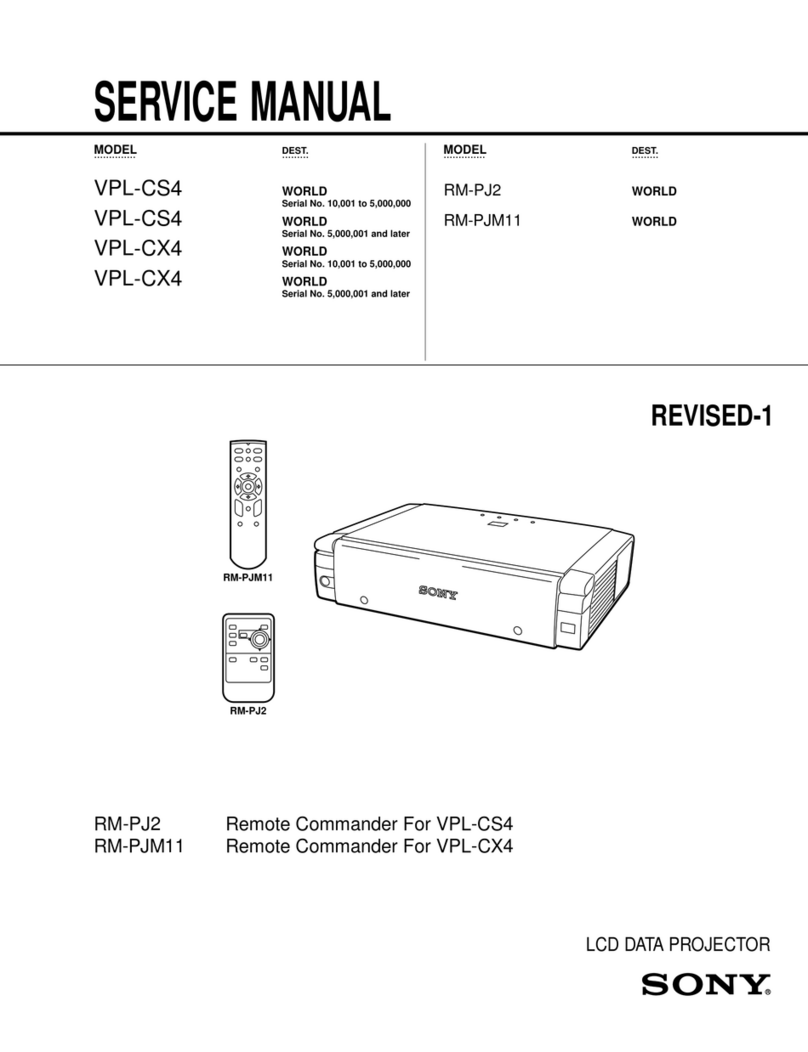
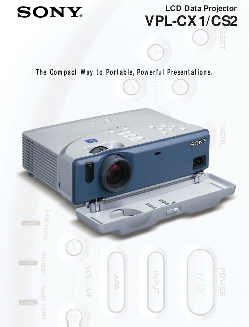
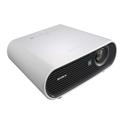
Sony VPL-CS5 User manual

.............. ......... ....................
SERVICE MANUAL
.............. ......... ....................
MODEL DEST. CHASSIS NO. MODEL DEST. CHASSIS NO.
VPL-CS5 WORLD
VPL-CX5 WORLD
RM-PJM12 WORLD
DATA PROJECTOR

VPL-CS5/CX5
!WARNING
This manual is intended for qualified service personnel only.
To reduce the risk of electric shock, fire or injury, do not perform any servicing other than that
contained in the operating instructions unless you are qualified to do so. Refer all servicing to
qualified service personnel.
!WARNUNG
Die Anleitung ist nur für qualifiziertes Fachpersonal bestimmt.
Alle Wartungsarbeiten dürfen nur von qualifiziertem Fachpersonal ausgeführt werden. Um die
Gefahr eines elektrischen Schlages, Feuergefahr und Verletzungen zu vermeiden, sind bei
Wartungsarbeiten strikt die Angaben in der Anleitung zu befolgen.Andere als die angegeben
Wartungsarbeiten dürfen nur von Personen ausgeführt werden, die eine spezielle Befähigung
dazu besitzen.
!AVERTISSEMENT
Ce manual est destiné uniquement aux personnes compétentes en charge de l’entretien.Afin
de réduire les risques de décharge électrique, d’incendie ou de blessure n’effectuer que les
réparations indiquées dans le mode d’emploi à moins d’être qualifié pour en effectuer d’autres.
Pour toute réparation faire appel à une personne compétente uniquement.
WARNING!!
AN INSULATEDTRANSFORMER SHOULD BE USED DURING
ANY SERVICE TO AVOID POSSIBLE SHOCK HAZARD, BE-
CAUSE OF LIVE CHASSIS.
THE CHASSIS OFTHIS RECEIVER IS DIRECTLY CONNECTED
TO THE AC POWER LINE.
SAFETY-RELATED COMPONENTWARNING !!
COMPONENTS IDENTIFIED BYA !!
!!
!MARKONTHESCHEMATIC
DIAGRAMS, EXPLODEDVIEWS AND INTHE PARTS LIST ARE
CRITICAL TO SAFE OPERATION. REPLACE THESE COMPO-
NENTSWITH SONY PARTSWHOSE PART NUMBERS APPEAR
AS SHOWN IN THIS MANUAL OR IN SUPPLEMENTS PUB-
LISHED BY SONY.
ATTENTION!!
AFIN D’ÉVITER TOUT RISQUE D’ÉLECTROCUTION
PROVENANT D’UN CHÂSSIS SOUS TENSION, UN
TRANSFORMATEURD’ISOLEMENTDOITETREUTILISÉLORS
DE TOUT DÉPANNAGE.
LE CHÂSSIS DE CE RÉCEPTEUR EST DIRECTEMENT
RACCORDÉ Á L’ALIMENTATION SECTEUR.
ATTENTION AUX COMPOSANTS RELATIFS Á LA
SÉCURITÉ!!
LES COMPOSANTS IDENTIFIÉS PAR UNE MAPQUE !!
!!
!SUR
LES SCHÉMAS DE PRINCIPE, LES VUES EXPLOSÉES ET LES
LISTES DE PIECES SONT D’UNE IMPORTANCE CRITIQUE
POUR LA SÉCURITÉ DU FONCTIONNEMENT. NE LES
REMPLACER QUE PAR DES COMPOSANTS SONY DONT LE
NUMÉRO DE PIÈCE EST INDIQUÉ DANS LE PRÉSENT
MANUEL OU DANS DES SUPPLÉMENTS PUBLIÉS PAR SONY.

VPL-CS5/CX5
For the customers in the Netherlands
Voor de klanten in Nederland
Hoe u de batterijen moet verwijderen, leest u in de tekst
van deze handleiding.
Gooi de batterij niet weg maar lever deze in als klein
chemisch afval (KCA).
Für Kunden in Deutschland
Entsorgungshinweis:Bitte werfen Sie nur entladene
Batterien in die Sammelboxen beim Handel oder den
Kommunen.Entladen sind Batterien in der Regel dann,
wenn das Gerät abschaltet und signalisiert “Batterie
leer”oder nach längerer Gebrauchsdauer der Batterien
“nicht mehr einwandfrei funktioniert”. Um
sicherzugehen, kleben Sie die Batteriepole z.B.mit
einem Klebestreifen ab oder geben Sie die Batterien
einzeln in einen Plastikbeutel.
1 (P)


1
VPL-CS5/CX5
Table of Contents
1. Service Information
1-1. Board Layout...............................................................................................1-1
1-2. Disassembly ................................................................................................1-2
1-2-1. Top Panel Assy Removal ...........................................................1-2
1-2-2. Side Panel Assy and L, NR, H2, Q Boards Removal ................1-2
1-2-3. Power Block (Lamp) Removal...................................................1-3
1-2-4. DC Fan Removal ........................................................................1-3
1-2-5. Lens Gear Removal ....................................................................1-4
1-2-6. Speaker Assy and DC Fan (Sirocco) Removal .........................1-4
1-2-7. C Board Removal .......................................................................1-5
1-2-8. MSC and MS (VPL-CX5) Boards Removal ..............................1-5
1-2-9. GA and GB Boards Removal .....................................................1-6
1-2-10. Optics Block Assy and Lamp Assy Removal ............................1-7
1-2-11. PS Com Aperture and In-polarizer (R), (G), (B) Removal ........1-8
1-2-12. Lens Projection Assy and Lamp Duct Assy Removal ...............1-9
1-2-13. Prism Block Assy and
Out-pre-polarizer (R), (G), (B) Removal .................................1-10
1-2-14. DC Fan (Sirocco) and V Board Removal ................................1-11
1-2-15. Adjustor Unit Removal ............................................................1-11
1-2-16. Extension Board and Extension Connectors ............................1-12
1-2-17. Extension Board and Extension Connectors Connection.........1-13
1-2-18. Warning on Power Connection ................................................1-14
2. Electrical Adjustments
2-1. Preparation ..................................................................................................2-1
2-1-1. Required Equipment...................................................................2-1
2-1-2. Optical Unit Adjustment ............................................................2-1
2-1-3. How to Enter the Factory Mode .................................................2-2
2-2. V COM Adjustment ....................................................................................2-2
2-3. Initial Values of Adjustment Items .............................................................2-3
2-4. Service Know-How .....................................................................................2-8
2-4-1. When the Prism Block Is Replaced............................................2-8
2-4-2. When the C Board Is Replaced ..................................................2-8
2-5. White Balance Adjustment .........................................................................2-8
2-5-1. HIGH Mode of INPUT-A ..........................................................2-8
2-5-2. LOW Mode of INPUT-A ...........................................................2-9
2-5-3. HIGH Mode of VIDEO..............................................................2-9
2-5-4. LOW Mode of VIDEO...............................................................2-9
2-6. Memory Structure .....................................................................................2-10

2VPL-CS5/CX5
3. Semiconductors................................................................................. 3-1
4. Spare Parts
4-1. Notes on Spare Parts ...................................................................................4-1
4-2. Exploded Views ..........................................................................................4-2
4-3. Electrical Parts List ...................................................................................4-14
5. Block Diagrams
Overall ....................................................................................................................5-1
C (1/4), Q................................................................................................................5-2
C (2/4).....................................................................................................................5-3
C (3/4), H1, H2, L, V, U, NR .................................................................................5-4
C (4/4).....................................................................................................................5-5
MS, MSC ................................................................................................................5-6
GA, GB...................................................................................................................5-7
6. Diagrams
6-1. Frame Schematic Diagrams ........................................................................6-2
Frame (1/2) ...............................................................................................6-2
Frame (2/2) ...............................................................................................6-3
6-2. Schematic Diagrams and Printed Wiring Boards........................................6-4
Schematic Diagrams
Q................................................................................................................6-4
C (1/10) .....................................................................................................6-6
C (2/10) .....................................................................................................6-7
C (3/10) .....................................................................................................6-8
C (4/10) .....................................................................................................6-9
C (5/10) ...................................................................................................6-10
C (6/10) ...................................................................................................6-11
C (7/10) ...................................................................................................6-12
C (8/10) ...................................................................................................6-13
C (9/10) ...................................................................................................6-14
C (10/10) .................................................................................................6-15
H1............................................................................................................6-20
H2............................................................................................................6-20
L ..............................................................................................................6-22
NR ...........................................................................................................6-22
U..............................................................................................................6-22
V..............................................................................................................6-22
MSC (1/2) ...............................................................................................6-24
MSC (2/2) ...............................................................................................6-25
3
VPL-CS5/CX5
MS (1/3) ..................................................................................................6-27
MS (2/3) ..................................................................................................6-28
MS (3/3) ..................................................................................................6-29
GA...........................................................................................................6-31
GB ...........................................................................................................6-34
Printed Wiring Boards
Q................................................................................................................6-5
C ..............................................................................................................6-16
H1............................................................................................................6-21
H2............................................................................................................6-21
L ..............................................................................................................6-23
NR ...........................................................................................................6-23
U..............................................................................................................6-23
V..............................................................................................................6-23
MSC ........................................................................................................6-26
MS...........................................................................................................6-30
GA...........................................................................................................6-32
GB ...........................................................................................................6-35


1-1
VPL-CS5/CX5
Section 1
Service Information
1-1. Board Layout
C
H1 NR
H2
MSC
MS
(VPL-CX5)
V
U
Q
Power block (Lamp)
GB
GA
L

1-2 VPL-CS5/CX5
1Six shafts
4H1 board
3Button (H1) assy
5Top panel assy
2Two screws
(+B 3 x6)
1-2. Disassembly
1-2-1. Top Panel Assy Removal
1-2-2. Side Panel Assy and L, NR, H2, Q Boards Removal
7Button (H2)
2Two screws
(+B 3 x6)
6Screw
(+B 3 x6)
9Screw
(+B 3 x6)
3Side panel assy
8H2 board
1Connector cover
!- Q board
0Video sleeve
4L board
5NR board
CN914
CN915
CN201

1-3
VPL-CS5/CX5
1-2-3. Power Block (Lamp) Removal
3Holder (LPS2)
4Holder (LPS1)
5Sheet (LPS)
6Power block (Lamp)
1Two screws
(+PTPWH 3 x10)
CN1
CN1
CN907
2Two screws
(+B 3 x6)
1-2-4. DC Fan Removal
4Fan holder (EX)
CN908
CN909
3Two DC fans
2Four screws
(+B 3 x20)
1Screw
(+B 3 x6)

1-4 VPL-CS5/CX5
1-2-5. Lens Gear Removal
2Lens gear
1Two screws
(+BTB 3 x12)
1-2-6. Speaker Assy and DC Fan (Sirocco) Removal
1Two screws
(+B 3 x6)
5Two screws
(+B 3 x6)
6Screw
(+B 3 x6)
3Two screws
(+BTB 3 x12)
9Speaker assy
7Speaker holder
8Speaker bracket
CN1102
CN912
4DC fan (Sirocco)
2Fan (RE) holder

1-5
VPL-CS5/CX5
1-2-7. C Board Removal
**
**
*: VPL-CX5
1Three screws
(+B 3 x6)
Flat connector assy
2C board
CN904
CN202 (VPL-CX5)
CN907
CN913
CN1101
CN901
CN911
CN910
CN914
CN912
CN909
CN908
CN1102
CN903
CN601*
CN602
CN501*
CN502
CN202*
CN904
CN701*
CN702
1-2-8. MSC and MS (VPL-CX5) Boards Removal
To remove the MS board, remove the C board beforehand.
2MSC board
4MS board
CN1303
CN1301
CN1002
CN1001
(VPL-CX5)
Flat connector assy
(12P) Flat connector assy
(50P)
3Two screws
(+B 3 x6)
1Screw
(+B 3 x6)

1-6 VPL-CS5/CX5
CN3301
CN3501
CN3201
CN2001CN2002
Flat connector assy
(24P)
7GB board
5GA board
6Holder GB
1Two screws
(+B 3 x6)
3Screw
(+B 3 x6)
2Screw
(+B 3 x6)
4Holder (GA),
Shield (GA)
1-2-9. GA and GB Boards Removal
To remove the GA and GB boards, remove the C board beforehand.

1-7
VPL-CS5/CX5
1-2-10.Optics Block Assy and Lamp Assy Removal
To remove the optics block assy and lamp assy, remove the DC fan beforehand.
4Four screws
(+)P M4x12
5Optics block
assy
1Two screws
(+PWHTP 3 x10)
6Lamp house,
Lamp top cover
2Connector
(Lamp)
7Lamp assy
3Two screws
(+B 3 x6)
Optics block assy

1-8 VPL-CS5/CX5
Note :Do not disassemble the optical block unless
specified by the above views.
!- In-polarizer (B)
5P/S converter
0In-polarizer (R)
9In-polarizer (G)
6PS com aperture
7Lens-2 fly eye
4Lens-1 fly eye
3UV-cut filter
2Unit cover (B), Four cushions
Optics block assy
1Two screws
(+B 2 x6)
8Three screws
(+B 2 x6)
1-2-11.PS Com Aperture and In-polarizer (R), (G), (B) Removal

1-9
VPL-CS5/CX5
1-2-12.Lens Projection Assy and Lamp Duct Assy Removal
To remove the lens projection assy and lamp duct assy , remove the C board, optics block assy and lamp assy
beforehand.
5Lamp duct assy
3Lens projection assy
1Four screws
(+B 4 x12)
2Four screws
(+BSW M3 x8)
4Two screws
(+B 3 x6)
6Screw
(+B 3 x6)
7Holder U
8U board

1-10 VPL-CS5/CX5
0Out-pre-polarizer (G)
7Out-pre-polarizer (B)
9Fastener (OP)
6Fastener (OP)
!- Prism block assy
4Out-pre-polarizer (R)
3Fastener (OP)
1Two screws
(+PS 3 x6)
8Screw
(+PAP 2 x5)
5Screw
(+PAP 2 x5)
2Screw
(+PAP 2 x5)
1-2-13.Prism Block Assy and Out-pre-polarizer (R), (G), (B) Removal
n
Do not touch the flexible cable, glass surface of prism and especially the conductor surface of flexible cables.

1-11
VPL-CS5/CX5
1-2-14.DC Fan (Sirocco) and V Board Removal
To remove the DC fan (sirocco) and V board, remove the C board, optics block assy, lamp assy
and prism block assy beforehand.
2Prism duct
8DC fan (sirocco)
7Two screws
(+BTB 3 x12)
1Two screws
(+B 3 x6)
3Screw (+B 3 x6)
6DC fan (sirocco)
9Fan holder (IN)
4V board
5Two screws
(+BTB 3 x12)
1Screw (+B 3 x6)
2Adjustor unit, Lens gear
1-2-15.Adjustor Unit Removal
To remove the adjustor unit, remove the C board, lamp assy, prism block assy and DC fan
(sirocco) beforehand.

1-12 VPL-CS5/CX5
Five ZH connectors assy (3P)
ZH connector assy (5P)
VH connector assy (3P)
SR connector assy (4P)
SR connector assy (7P)
SR connector assy (14P)
Flat connector assy (24P)
Three flat connectors assy (32P)
(VPL-CX5)
Three flat connectors assy (24P)
(VPL-CS5)
X1 board
X5 board
X kit assy
(A-1603-729-A)
Three X2 boards
(VPL-CX5)
Three X3 boards
(VPL-CS5) X4 board
SR connector assy (5P)
SR connector assy (12P)
1-2-16.Extension Board and Extension Connectors
Other manuals for VPL-CS5
3
This manual suits for next models
2
Table of contents
Other Sony Projector manuals

Sony
Sony KP-53XBR45 - 53" Projection Tv User manual

Sony
Sony VPL-BW7 User manual

Sony
Sony VPL-VW695ES Service manual

Sony
Sony VPL-HW65ES Service manual

Sony
Sony VPL-CX70 User manual

Sony
Sony BRAVIA VPL-VW70 User manual

Sony
Sony VPH-G70VRU User manual

Sony
Sony VPL-PX1 User manual

Sony
Sony KPR-4110 User manual

Sony
Sony VPD-MX10 User manual

Sony
Sony VPL-FHZ61 User manual

Sony
Sony VPL-FX500L User manual

Sony
Sony SRX-R320 User manual

Sony
Sony VPL-VW760/B Service manual

Sony
Sony VPL-VW290ES User manual

Sony
Sony VPL-CS10 User manual

Sony
Sony VPL-EX130 User manual

Sony
Sony VPL-CX125 User manual

Sony
Sony VPL-EW575 User manual

Sony
Sony VPLFH31/B User manual