2
Table of Contents
Overview
Location and Function of Controls .................... 4
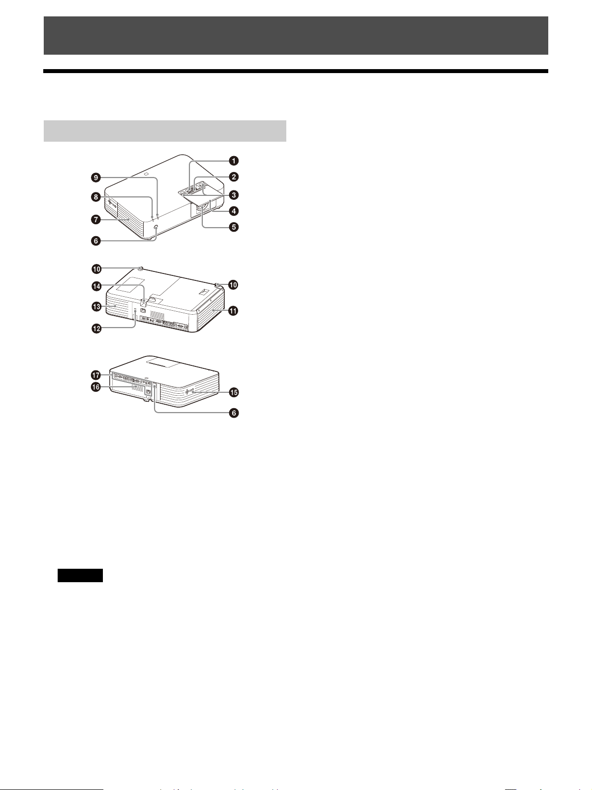
Main Unit ....................................................... 4
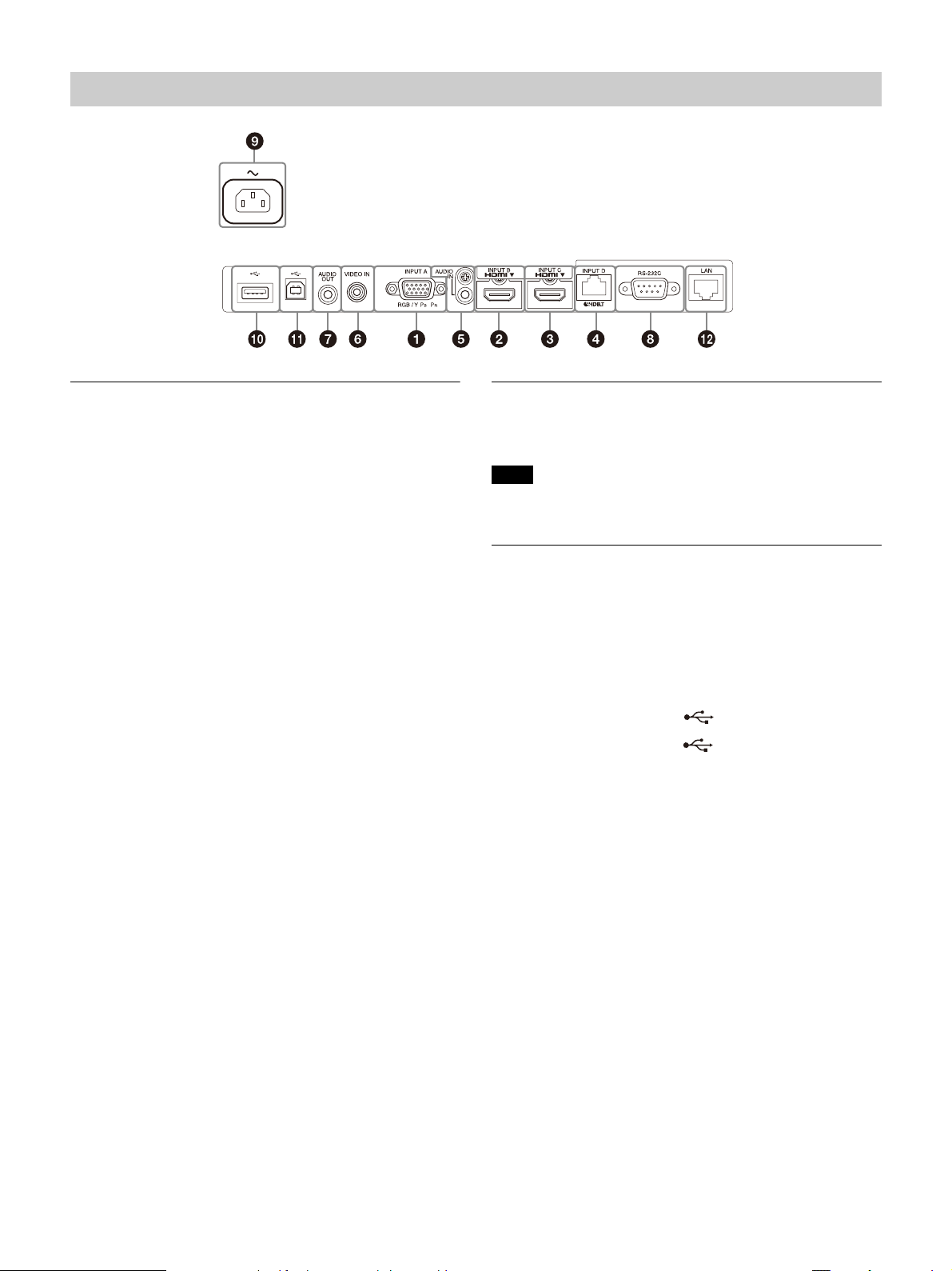
Terminals ....................................................... 5
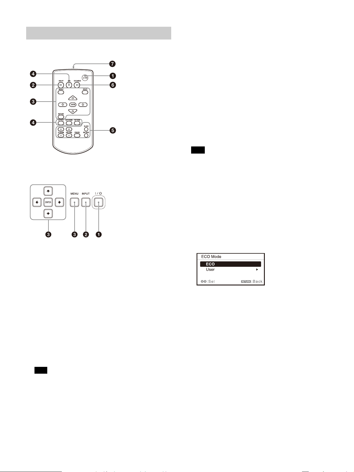
Remote Commander and Control Panel
Keys ............................................................ 6
Preparation
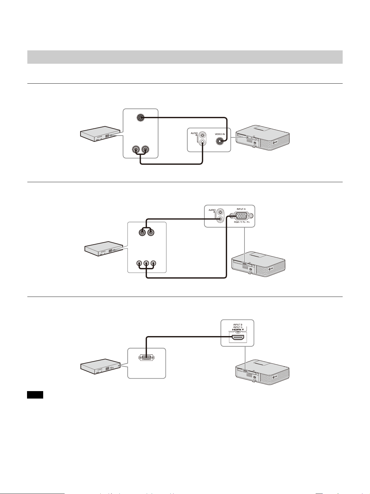
Connecting the Projector .................................. 8
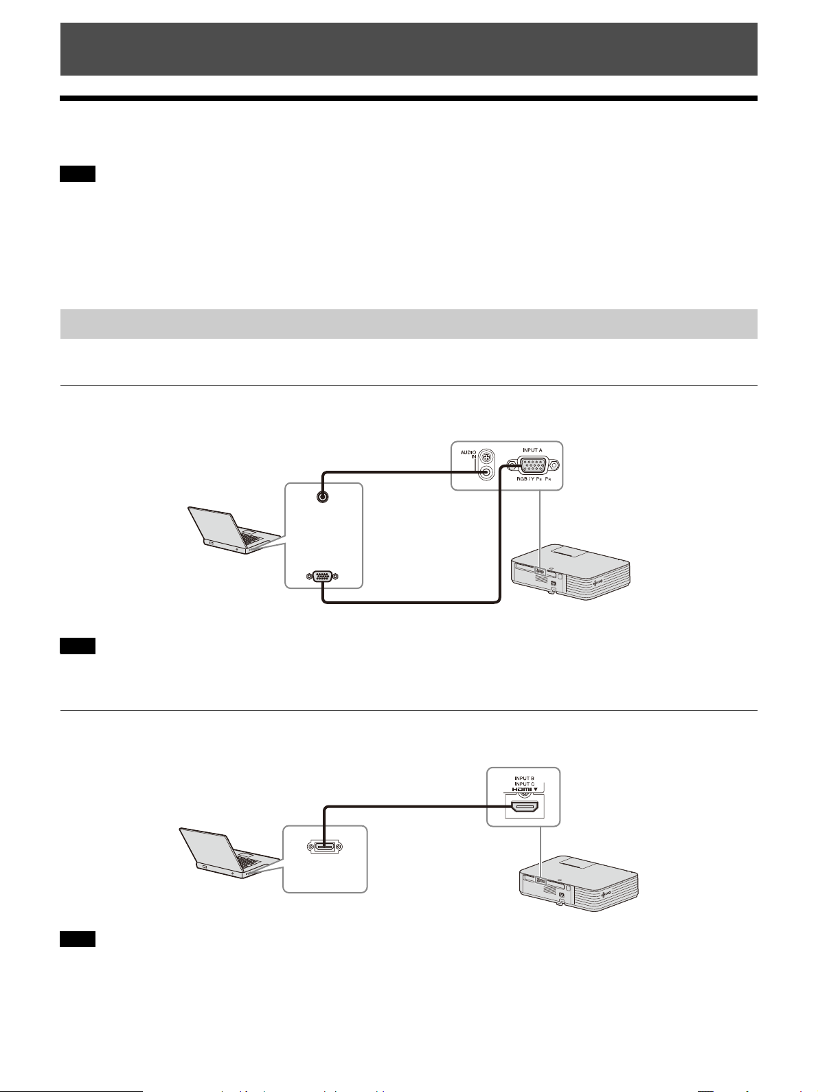
Connecting a Computer ................................ 8
Connecting a Video equipment ..................10
Connecting a HDBaseT™ equipment ...........11
Connecting Audio Equipment ..................... 13
Projecting/Adjusting an Image
Projecting an Image .........................................14
Adjusting the Focus, Size, and Position of the
Projected Image ........................................ 15
Turning Off the Power ................................. 17
Adjustments and Settings Using a Menu
Using a MENU ...................................................18
Projection Setting Menu ...................................19
The Screen Menu .............................................. 21
The Function Menu ...........................................23
The Operation Menu ....................................... 24
The Connection/Power Menu ......................... 25
The Installation Menu .......................................27
The Information Menu .................................... 28
Network
Using Network Features .................................. 29
Displaying the Control Window of the
Projector with a Web Browser ................. 29
Confirming the Information regarding the
Projector ................................................... 30
Operating the Projector from a
Computer ................................................. 30
Using the e-mail report Function ............... 30
Setting the LAN Network of the
projector .................................................... 31
Setting the WLAN Network of the
projector ....................................................32
Setting the Custom Labels for the Input
Terminals of the Projector ........................ 34
Setting the Control Protocol of the
Projector ................................................... 34
Using the Software Update Function ..........37
Presentation Function via Network
Using Presentation Function via Network ...... 38
Installing Projector Station for Network
Presentation ............................................. 38
Starting Projector Station for Network
Presentation ............................................. 38
Projecting an Image .................................... 38
Connection Settings .................................... 40
Using the Controller .................................... 40
One-Click projecting function .................... 40
Option format ..............................................41
Use Projector Station for Network
Presentation without installing it to the
computer. ..................................................41
Error code list of Projector Station for Projector
Station for Network Presentation ............ 42
Playing Video and Audio using USB
Connection
Playing Video and Audio using USB
Connection .................................................... 43
Starting USB Display ................................... 43
Playing Video and Audio ............................ 43
Using the Controller .................................... 43
Error Handling
Indicators ......................................................... 44
Messages List .................................................. 46
Troubleshooting ...............................................47