Sony HCD-ZX80D User manual

SERVICE MANUAL
DVD DECK RECEIVER
US Model
HCD-ZX80D
E Model
HCD-ZX80D/ZX100D
HCD-ZX80D/ZX100D
Ver. 1.2 2007.08
SPECIFICATIONS
9-887-251-03
2007H05-1
© 2007.08
Sony Corporation
Personal Audio Division
Published by SonyTechno Create Corporation
•HCD-ZX80D is the amplifier, disc player, tape deck
and tuner section in FST-ZX80D/LBT-ZX80D.
•HCD-ZX100D is the amplifier, disc player, tape deck
and tuner section in FST-ZX100D/LBT-ZX100D.
DVD Model Name Using Similar Mechanism NEW
Section DVD Mechanism Type CDM74HF-DVBU101
Optical Pick-up Block Name KHM-310CAB or KHM-313CAB
Tape deck Model Name Using Similar Mechanism NEW
Section Tape Transport Mechanism Type CWN42RR603
– Continued on next page –
Photo: HCD-ZX80D
This system incorporates Dolby* Digital, Dolby
Pro Logic (II) adaptive matrix surround decoder,
and the DTS** Digital Surround System.
* Manufactured under license from Dolby
Laboratories.
“Dolby”, “Pro Logic”, and the double-D
symbol are trademarks of Dolby
Laboratories.
**Manufactured under license from Digital
Theater Systems, Inc.
“DTS” and “ DTS Digital Surround” are
registered trademarks of Digital Theater
Systems, Inc.
Amplifier section
HCD-ZX100D
The following are measured atAC 120, 127, 220,
240V 50/60 Hz
DIN power output (rated): 130 W + 130 W
(6 ohms at 1 kHz, DIN)
Continuous RMS power output (reference)
Front speaker: 170 W + 170 W
(6 ohms at 1 kHz, 10% THD)
Center speaker: 80 W
(16 ohms at 1 kHz, 10%
THD)
Surround speaker: 170 W + 170 W
(6 ohms at 1 kHz, 10%
THD)
Subwoofer: 180 W (8 ohms at 100 Hz,
10% THD)
HCD-ZX80D
The following are measured atAC 120, 127, 220,
240V 50/60 Hz
DIN power output (rated):155 W + 155 W
(6 ohms at 1 kHz, DIN)
Continuous RMS power output (reference)
Front speaker: 200 W + 200 W
(6 ohms at 1 kHz, 10%
THD)
Center speaker: 80 W
(16 ohms at 1 kHz, 10%
THD)
Surround speaker: 200 W + 200 W
(6 ohms at 1 kHz, 10%
THD)
Inputs
VIDEO INPUT (phono jacks):
VIDEO: 1 Vp-p, 75 ohms
AUDIO L/R: Voltage
250 mV, impedance 47
kilohms
TV/SAT AUDIO IN L/R (phono jacks):
Voltage 250 mV/450 mV,
impedance 47 kilohms
MIC 1 or 2 (phone jack): Sensitivity 1 mV,
impedance 10 kilohms
Outputs
AUDIO OUT (phono jacks):
Voltage 250 mV,
impedance 1 kilohm
VIDEO OUT (phono jack):Max. output level 1 Vp-p,
unbalanced, Sync.
negative load impedance
75 ohms
COMPONENT VIDEO OUT:
Y: 1 Vp-p, 75 ohms
PB/CB: 0.7 Vp-p, 75 ohms
PR/CR: 0.7 Vp-p, 75 ohms
AUDIO POWER SPECIFICATION
(HCD-ZX80D USA model only)
POWER OUTPUT AND TOTAL HARMONIC
DISTORTION:
With 6-ohm loads, both channels driven, from
120 Hz −10 kHz; rates 160 watts per channel
minimum RMS power, with no more than 10% total
harmonic distortion from 250 milliwatts to rated output.
Continuous RMS power output (reference)
Front speaker: 200 W + 200 W
(6 ohms at 1 kHz, 10% THD)
Center speaker: 80 W
(16 ohms at 1 kHz, 10%
THD)
Surround speaker: 200 W + 200 W
(6 ohms at 1 kHz, 10% THD)

2
HCD-ZX80D/ZX100D
SAFETY-RELATED COMPONENT WARNING!!
COMPONENTS IDENTIFIED BY MARK 0 OR DOTTED LINE
WITH MARK 0ON THE SCHEMATIC DIAGRAMS AND IN
THE PARTS LIST ARE CRITICAL TO SAFE OPERATION.
REPLACE THESE COMPONENTS WITH SONY PARTS WHOSE
PART NUMBERS APPEAR AS SHOWN IN THIS MANUAL OR
IN SUPPLEMENTS PUBLISHED BY SONY.
Tuner section
FM stereo, FM/AM superheterodyne tuner
FM tuner section
Tuning range 87.5 −108.0 MHz
(50 kHz step)
Antenna FM lead antenna
Antenna terminals 75 ohms unbalanced
Intermediate frequency 10.7 MHz
AM tuner section
Tuning range
PanAmerican models: 530 −1,710 kHz
(with the interval set at
10 kHz)
531 −1,710 kHz
(with the interval set at
9 kHz)
Other models: 531 −1,602 kHz
(with the interval set at
9 kHz)
530 −1,710 kHz
(with the interval set at
10 kHz)
Antenna AM loop antenna
Antenna terminals External antenna terminal
Intermediate frequency 450 kHz
General
Power requirements
Mexican model: 127 V AC, 60 Hz
US model: 120 V AC, 60 Hz
Other models: 120 V, 220 V or
230 −240 V AC, 50/60 Hz
Adjustable with voltage
selector
Power consumption
HCD-ZX100D 430 W
HCD-ZX80D 390 W
Dimensions (w/h/d) (Approx.)
281 ×379 ×404.5 mm
(11 1/8 ×15 ×16 in.)
Mass (Approx.) 16.3 kg
(35 lb 15 oz)
Design and specifications are subject to change
without notice.
Frequency response DVD (PCM 48 kHz):
2 Hz −22 kHz (±1dB)
CD: 2 Hz −20 kHz
(±0.5 dB)
Video color system format
Pan American models: NTSC
Other models: NTSC and PAL
Tape deck section
Recording system 4-track 2-channel stereo
Frequency response 50 −13,000 Hz (±3 dB),
using Sony TYPE I tape
Disc player section
System Compact disc and digital
audio and video system
Laser Semiconductor laser
(DVD: λ = 650 nm,
CD: λ= 790 nm)
Emission duration:
continuous
CENTER SPEAKER: Use only the supplied
speaker
SUBWOOFER OUT:
HCD-ZX100D: Use only the supplied
subwoofer
HCD-ZX80D (phono jacks):
Voltage 250 mV,
impedance 1 kilohm
SURR SPEAKER: Use only the supplied
speakers
PHONES (stereo mini jack):
accepts headphones of
8 ohms or more
FRONT SPEAKER: Use only the supplied
speakers
S VIDEO OUT (4-pin/mini-DIN jack):
Y: 1 Vp-p, unbalanced,
Sync. negative
C: 0.286 Vp-p, load
impedance 75 ohms
Ver. 1.1

3
HCD-ZX80D/ZX100D
Notes on chip component replacement
•Never reuse a disconnected chip component.
•Notice that the minus side of a tantalum capacitor may be
damaged by heat.
Flexible Circuit Board Repairing
•Keep the temperature of the soldering iron around 270 ˚C
during repairing.
•Do not touch the soldering iron on the same conductor of the
circuit board (within 3 times).
•Be careful not to apply force on the conductor when soldering
or unsoldering.
CAUTION
Use of controls or adjustments or performance of procedures
otherthan thosespecifiedherein may result in hazardous radiation
exposure.
SELF DIAGNOSIS FUNCTION
(When letters/numbers appear in the
display)
When the self-diagnosis function is activated to
prevent the system from malfunctioning, a
5-character service number (e.g. C 13 50) with a
combination of a letter and 4 digits appears on
the TV screen and the front panel display. In this
case, check the following table.
When displaying the version number on the
TV screen
When you turn on the system, the version
number [VER.X.XX] (X is a number) may
appear on the TV screen.Although this is not a
malfunction and for Sony service use only,
normal system operation will not be possible.
Turn off the system, and then turn on the system
again to operate.
Self-diagnosis Function
First 3
characters of
the service
number
Cause and corrective action
C 13 This disc is dirty.
• Clean the disc with a soft cloth.
C 31 The disc is not inserted correctly.
• Restart the system, then re-insert
the disc correctly.
E XX
(XX is a
number)
To prevent a malfunction, the system
has performed the self-diagnosis
function.
• Contact your nearest Sony dealer or
local authorized Sony service
facility and give the 5-character
service number.
Example: E 61 10
VER.X.XX
This appliance is
classified as a CLASS 1
LASER product. This
label is located on the
rear exterior.
The following caution label is located inside the
apparatus.
Ver. 1.1
SAFETY CHECK-OUT
After correcting the original service problem, perform the following
safety check before releasing the set to the customer:
Check the antenna terminals, metaltrim, “metallized” knobs, screws,
and all other exposed metal parts forAC leakage.
Check leakage as described below.
LEAKAGE TEST
The AC leakage from any exposed metal part to earth ground and
from all exposed metal parts to any exposed metal part having a
return to chassis, must not exceed 0.5 mA (500 microamperes.).
Leakage current can be measured by any one of three methods.
1. A commercial leakage tester, such as the Simpson 229 or RCA
WT-540A. Follow the manufacturers’instructions to use these
instruments.
2. A battery-operatedAC milliammeter. The Data Precision 245
digital multimeter is suitable for this job.
3. Measuring the voltage drop across a resistor by means of a
VOMor battery-operatedACvoltmeter.The “limit” indication
is 0.75V, so analog meters must have an accurate low-voltage
scale. The Simpson 250 and Sanwa SH-63Trd are examples
of a passive VOM that is suitable. Nearly all battery operated
digital multimeters that have a 2VAC range are suitable. (See
Fig. A)
Fig. A. Using an AC voltmeter to check AC leakage.
1.5 k
Ω
0.15
µ
FAC
voltmete
r
(0.75 V)
To Exposed Metal
Parts on Set
Earth Ground

4
HCD-ZX80D/ZX100D
TABLE OF CONTENTS
1. SERVICING NOTES ............................................... 5
2. GENERAL ................................................................... 7
3. DISASSEMBLY
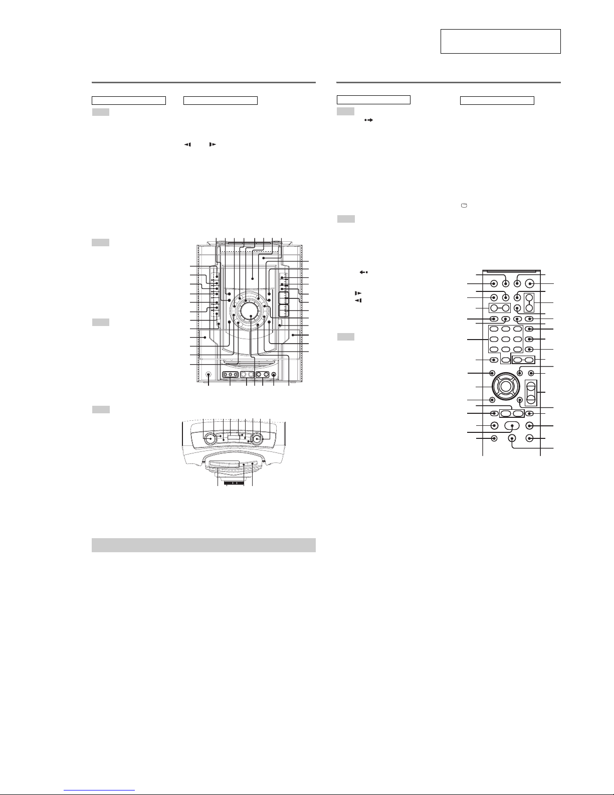
3-1. Disassembly Flow ........................................................... 8
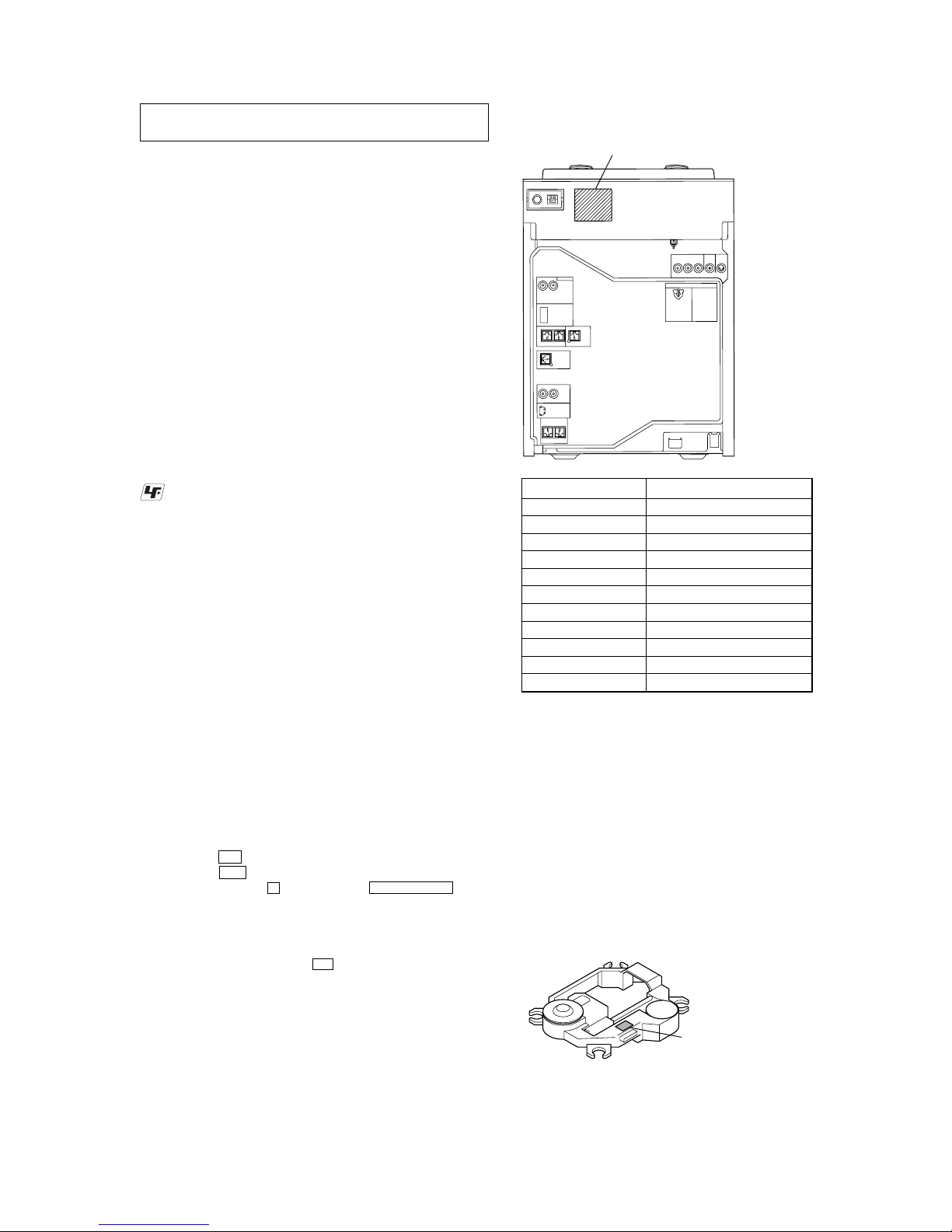
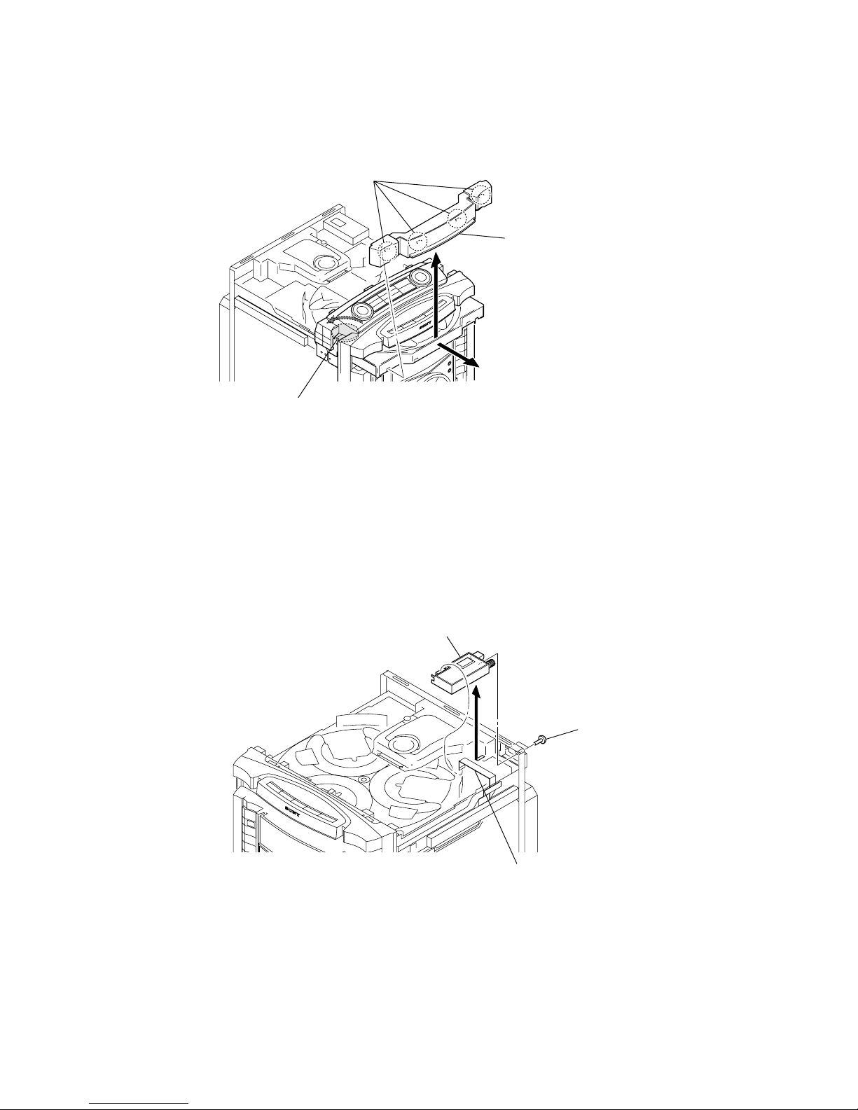
3-2. Case ................................................................................. 9
3-3. Escution Top Block ......................................................... 9
3-4. Loading Panel .................................................................. 10
3-5. Tuner (FM/AM) (TM10SE) ............................................ 10
3-6. DVD Mechanism Deck Block ......................................... 11
3-7. Front Panel Block ............................................................ 11
3-8. Back Panel Block ............................................................ 12
3-9. MAIN Board Block ......................................................... 12
3-10. MAIN Board.................................................................... 13
3-11. Cover (CDM)................................................................... 13
3-12. DRIVER Board, SW Board............................................. 14
3-13. Optical Pick-Up Block
(KHM-310CAB or KHM-313CAB) ............................... 14
3-14. SENSOR Board ............................................................... 15
3-15. MOTOR (TB) Board ....................................................... 15
3-16. MOTOR (LD) Board ....................................................... 16
4. TEST MODE.............................................................. 17
5. MECHANICAL ADJUSTMENTS ....................... 21
6. ELECTRICAL ADJUSTMENTS ......................... 21
7. DIAGRAMS
7-1. Block Diagram – RF SERVO/VIDEO Section – ............ 23
7-2. Block Diagram – MIC/EFFECTOR Section –................ 24
7-3. Block Diagram – TUNER/TAPE Section – .................... 25
7-4. Block Diagram – AUDIO Section – ................................ 26
7-5. Block Diagram – AMP Section – .................................... 27
7-6. Block Diagram
– PANEL/POWER SUPPLY Section – ........................... 28
7-7. Printed Wiring Board – DMB15 Board (SideA) – ......... 30
7-8. Printed Wiring Board – DMB15 Board (Side B) – ......... 31
7-9. Schematic Diagram – DMB15 Board (1/4) –.................. 32
7-10. Schematic Diagram – DMB15 Board (2/4) –.................. 33
7-11. Schematic Diagram – DMB15 Board (3/4) –.................. 34
7-12. Schematic Diagram – DMB15 Board (4/4) –.................. 35
7-13. Printed Wiring Boards – CHANGER Section – .............. 36
7-14. Schematic Diagram – CHANGER Section – .................. 37
7-15. Printed Wiring Board – VIDEO Board –......................... 38
7-16. Schematic Diagram – VIDEO Board – ........................... 39
7-17. Printed Wiring Board – MIC Board – ............................. 40
7-18. Schematic Diagram – MIC Board – ................................ 41
7-19. Printed Wiring Board – EFFECTOR Board – ................. 42
7-20. Schematic Diagram – EFFECTOR Board –.................... 43
7-21. Printed Wiring Board – KARAOKE Board – ................. 44
7-22. Schematic Diagram – KARAOKE Board – .................... 44
7-23. Printed Wiring Board – MAIN Board – .......................... 45
7-24. Schematic Diagram – MAIN Board (1/6) – .................... 46
7-25. Schematic Diagram – MAIN Board (2/6) – .................... 47
7-26. Schematic Diagram – MAIN Board (3/6) – .................... 48
7-27. Schematic Diagram – MAIN Board (4/6) – .................... 49
7-28. Schematic Diagram – MAIN Board (5/6) – .................... 50
7-29. Schematic Diagram – MAIN Board (6/6) – .................... 51
7-30. Printed Wiring Board – PA Board – ................................ 52
7-31. Schematic Diagram – PA Board – ................................... 53
7-32. Printed Wiring Board – SURROUND Board – ............... 55
7-33. Schematic Diagram – SURROUND Board (1/2) – ......... 56
7-34. Schematic Diagram – SURROUND Board (2/2) – ......... 57
7-35. Printed Wiring Board – PANEL Board – ........................ 58
7-36. Schematic Diagram – PANEL Board – ........................... 59
7-37. Printed Wiring Boards – FRONT KEY Section – ........... 60
7-38. Schematic Diagram – FRONT KEY Section – ............... 61
7-39. Printed Wiring Boards – TOP KEY Section – ................ 62
7-40. Schematic Diagram – TOP KEY Section –..................... 63
7-41. Printed Wiring Board – TRANSFORMER Board – ....... 64
7-42. Printed Wiring Board – PRIMARY Board – ................... 65
7-43. Schematic Diagram – POWER SUPPLY Section – ........ 66
8. EXPLODED VIEWS
8-1. Case, Escutcheon Top Section......................................... 81
8-2. PANEL Board Section..................................................... 82
8-3. Tape Mecha Deck Section ............................................... 83
8-4. Back Panel Section .......................................................... 84
8-5. DMB15/KARAOKE/VIDEO Boards Section................. 85
8-6. MAIN/PA/SURROUND Boards Section ........................ 86
8-7. Power Transformer Section ............................................. 87
8-8. DVD Mechanism Deck Section-1
(CDM74HF-DVBU101).................................................. 88
8-9. DVD Mechanism Deck Section-2
(CDM74HF-DVBU101).................................................. 89
9. ELECTRICAL PARTS LIST................................ 90
Note: Refer to SUPPLEMENT-1 for the MAIN board of printed
wiring board, schematic diagram and electrical parts list of
US model.
Ver. 1.1

5
HCD-ZX80D/ZX100D
MODEL IDENTIFICATION
– Back Panel –
Label indication Model
2-661-760-5[] E2 ZX80D: E2
2-661-760-6[] E2 ZX100D: E2
2-661-761-3[] MX ZX100D: MX
2-661-761-4[] MX ZX80D: MX
2-672-142-0[] E3 ZX100D: E3
2-672-142-1[] E3 ZX80D: E3
2-675-973-2[] E51 ZX80D: E51
2-675-973-3[] E51 ZX100D: E51
2-686-974-1[] SP2/6 ZX100D: SP, MY
2-686-106-0[] E13 ZX80D: E3
2-899-693-0[] U2 ZX80D: US
•Abbreviation
E2 : 120V AC area in E model
E3 : 240V AC area in E model
E13 : Russian model and 220V – 230VAC area in E model
E51 : Chilean and Peruvian models
MX : Mexican model
MY : Malaysia model
SP : Singapore model
HOW TO IDENTIFY OPTICAL PICK-UP BLOCK
There are two kinds of OPTICAL PICK-UP BLOCK in this set.
Whenreplacing the OPTICALPICK-UP BLOCK, makesure which
OPTICAL PICK-UP BLOCK it is following the “How to Identify”
in the figure shown below.
SECTION 1
SERVICING NOTES
NOTES ON HANDLING THE OPTICAL PICK-UP
BLOCK OR BASE UNIT
The laser diode in the optical pick-up block may suffer electrostatic
break-down because of the potential difference generated by the
charged electrostatic load, etc. on clothing and the human body.
During repair, pay attention to electrostatic break-down and also
use the procedure in the printed matter which is included in the
repair parts.
The flexible board is easily damaged and should be handled with
care.
NOTES ON LASER DIODE EMISSION CHECK
The laser beam on this model is concentrated so as to be focused on
the disc reflective surface by the objective lens in the optical pick-
up block. Therefore, when checking the laser diode emission,
observe from more than 30 cm away from the objective lens.
UNLEADED SOLDER
Boards requiring use of unleaded solder are printed with the lead-
free mark (LF) indicating the solder contains no lead.
(Caution: Some printed circuit boards may not come printed with
the lead free mark due to their particular size)
: LEAD FREE MARK
Unleaded solder has the following characteristics.
•Unleaded solder melts at a temperature about 40 °C higher
than ordinary solder.
Ordinary soldering irons can be used but the iron tip has to be
applied to the solder joint for a slightly longer time.
Soldering irons using a temperature regulator should be set to
about 350 °C.
Caution: The printed pattern (copper foil) may peel away if
the heated tip is applied for too long, so be careful!
•Strong viscosity
Unleaded solder is more viscou-s (sticky, less prone to flow)
than ordinary solder so use caution not to let solder bridges
occur such as on IC pins, etc.
•Usable with ordinary solder
It is best to use only unleaded solder but unleaded solder may
also be added to ordinary solder.
RELEASING THE DVD TRAY LOCK
The disc tray lock function for the antitheft of an demonstration
disc in the store is equipped.
Releasing Procedure :
1. Press the I/1button to turn the power on.
2. Press the DVD button to select “DVD”.
3. Whilepressing the xbutton, press the ZOPEN/CLOSE button
until “UNLOCKED” displayed on the fluorescent indicator
tube (around 5 seconds).
Note: When “LOCKED” is displayed, the disc tray lock is not released by
turning power on/off with the I/1button.
NOTES ON REPLACEMENT OF THE DMB15 BOARD
New part of EEPROM (IC103) on the DMB15 board cannot be
used.Therefore, if the mounted DMB15 board is replaced, exchange
new EEPROM with that used before the replacement.
Model number label
Printed of KHM-310CAB or KHM-313CAB.
KHM-310CA
B
or
KHM-313CA
B
Ver. 1.1

6
HCD-ZX80D/ZX100D
You can play back the following discs on this
system. Other discs cannot be played back.
List of playable discs
“DVD+RW”, “DVD-RW”, “DVD+R”,
“DVD VIDEO”, and the “CD” logos are
trademarks.
Notes on discs
The system can play back the following disc:
• CD-ROMs/CD-Rs/CD-RWs recorded in the
following formats:
– VIDEO CD format
– AUDIO CD format
– CD Graphics (Latin American models
only)
– DATA CD format which contains MP3
audio tracks, JPEG image files and DivX
1)
video files of format conforming to ISO
2)
9660 Level 1, Level 2 or Joliet in
3)
expansion format
•DVD-ROMs/DVD-Rs/DVD-RWs/DVD+Rs/
DVD+RWs recorded in the following
formats:
– DVD VIDEO format
– DATA DVD format which contains MP3
audio tracks, JPEG image files and DivX
1)
video files of format conforming to UDF
2)
(Universal Disk Format)
– VR (Video Recording) format (DVD-Rs/
DVD-RWs only)
The system cannot play back the following
discs:
1)
MP3 audio tracks must be in MPEG 1 Audio
Layer 3 format.
2)
DivX video files must be recorded in DivX format
with the extension “.AVI” or “.DIVX”. (Except US model)
3)
ISO 9660 Format
A logical format of files and folders on CD-ROMs,
defined by ISO (International Organization for
Standardization).
Playable discs
Format of discs Disc logo
DVD VIDEO
DVD-RW/DVD-R
DVD+RW/
DVD+R
VIDEO CD
AUDIO CD
CD Graphics
(CDG)
(Latin American
models only)
CD-R/CD-RW
4)
CD-Extra: This format records audio (AUDIO CD
data) on the tracks in session 1 and data on the tracks
in session 2.
5)
Mixed CD: This format records data on the first track
and audio (AUDIO CD data) on the second and
subsequent tracks of a session.
Region code of DVD VIDEOs
you can play back on this
system
Your system has a region code printed on the
back of the unit and will only play back DVD
VIDEOs labeled with identical region code.
DVD VIDEOs labeled will also be played
back on this system.
If you try to play back any other region code
DVD VIDEO, the message “Playback
prohibited by area limitations.” will appear on
the TV screen. Depending on the DVD VIDEO,
no region code indication may be labeled even
though playing the DVD VIDEO is prohibited
by area restrictions.
Example:
Note on DualDiscs
A DualDisc is a two sided disc product which
mates DVD recorded material on one side with
digital audio material on the other side.
However, since the audio material side does not
conform to Compact Disc (CD) standard,
playback on this product is not guaranteed.
ALL
DVD DECK RECEIVER
MODELN0. HCD-ZX100D
SERIAL NO.
AC:120-127/220/230-240V 50/60Hz430W
Region code
Notes on CD-R/CD-RW/DVD-R/
DVD-RW/DVD+R/DVD+RW
• In some cases, CD-Rs/CD-RWs/DVD-Rs/
DVD-RWs/DVD+Rs/DVD+RWs cannot be
played back on this system due to the
recording quality or physical condition of the
disc, or the characteristics of the recording
device and authoring software. The disc will
not be played back if it has not been correctly
finalized. For more information, see the
operation instructions for the recording
device.
• Note that some playback functions may not
work with some DVD+RWs/DVD+Rs, even
if they have been correctly finalized. In this
case, view the disc by normal playback.
•Adisc created in Packet Write format cannot
be played back.
Note on playback operations
of DVD VIDEOs and VIDEO
CDs
Some playback operations of DVD VIDEOs and
VIDEO CDs may be intentionally set by
software producers. Since this system play back
DVD VIDEOs and VIDEO CDs according to
the disc contents the software producers
designed, some playback features may not be
available. Also, refer to the instructions supplied
with the DVD VIDEOs or VIDEO CDs.
Note on PBC (Playback
Control) (VIDEO CDs)
This system conforms to Ver. 1.1 and Ver. 2.0 of
VIDEO CD standards. You can enjoy two kinds
of playback depending on the disc type.
Disc type You can
VIDEO CDs
without PBC
functions
(Ver. 1.1 discs)
Enjoy video playback (moving
pictures) as well as music.
Music discs encoded with
copyright protection
technologies
This product is designed to play back discs that
conform to the Compact Disc (CD) standard.
Recently, various music discs encoded with
copyright protection technologies are marketed
by some record companies. Please be aware that
among those discs, there are some that do not
conform to the CD standard and may not be
playable by this product.
Notes on Multi Session disc
• This system can play back Multi Session discs
when an MP3 audio track is contained in the
first session. Any subsequent MP3 audio
tracks recorded in later sessions can also be
played back.
• This system can play back Multi Session discs
when a JPEG image file is contained in the
first session. Any subsequent JPEG image
files recorded in later sessions can also be
played back.
• If the first session is recorded in AUDIO CD
or VIDEO CD format, only the first session
will be played back.
VIDEO CDs
with PBC
functions
(Ver. 2.0 discs)
Play back interactive software
using menu screens displayed on
the TV screen (PBC Playback), in
addition to the video playback
functions of Ver. 1.1 discs.
Moreover, you can play back high-
resolution still pictures, if they are
included on the disc.
Disc type You can
•The system will recognize a Multi Session
disc as an AUDIO CD if there is a session
recorded in AUDIO CD format on the disc.
However, the system will only play back the
disc if the first session is recorded in AUDIO
CD format.
•With DATA CD or DATA DVD, the system
will only play back DivX video files even if it
contains MP3 audio tracks or JPEG image
files.
• CD-ROMs recorded in PHOTO CD format
• Data part of CD-Extras
4)
• Data part of Mixed CDs
5)
• Super Audio CDs
•DVD Audio discs
•DVD-RAMs
•ADVD VIDEO with a different region code.
•Adisc that has a non-standard shape (e.g.,
heart, square, star).
•Adisc that has the adhesive cellophane tape
or a sticker still left on it.
Ver. 1.1

7
HCD-ZX80D/ZX100D
SECTION 2
GENERAL This section is extracted from
instruction manual.
LOCATION OF CONTROLS
Remote control
ADVANCE wf
ALBUM +/– qa
ANGLE q;
AUDIO 8
CLEAR wk
DISC SKIP 3
DISPLAY ed
ENTER wh
FM MODE 7
FUNCTION +/– 4
KARAOKE MODE ea
KARAOKE PON e;
KEY CONTROL #/2 es
MENU qs
Numeric Buttons
1)
wl
PICTURE NAVI 6
PRESET + qh
PRESET – wd
REPEAT 7
REPLAY wf
SCORE 5
SLEEP eg
SLOW qj
SLOW ws
SOUND FIELD qd
STEP C wf
SUBTITLE 9
THEATRE SYNC 1
TIMER MENU eh
TIME/TEXT ef
TOP MENU wj
TUNING + qj
TUNING – ws
TV w;
TV CH + qh
TV CH – wd
TV/VIDEO eg
TV VOL +/– qf
1)
TV &/1 (on/standby) 2
VOLUME +/– qf
1)
?/1 (on/standby) 2
x(stop) qk
X(pause) ql
H
1)
(play) wa
>(go forward) qh
.(go backward) wd
M(fast forward) qj
m(rewind) ws
V
/
v
/
B
/
b
wh
10/0 wl
-/-- wk
ORETURN wg
DISPLAY qg
c STEP wf
1)
Thenumericbutton5,TVVOL
+, VOLUME + and H
buttons have a tactile dot. Use
the tactile dot as a reference
when operating the system.
ALPHABETICAL ORDER
A – L
M – S
T – Z
NUMBERS AND SYMBOLS
Unit
AMP MENU e;
BALANCE rh
BEAT JUMP rs
BEAT MAX ra
BEAT PAD r;
CD SYNC q;
CHORUS wl
Deck A ea
Deck B qk
DELAY wk
DIRECTION ql
DISC 1 ~ 3 ts
Disc tray 8
DISPLAY 2
Display 6
DVD ej
ECHO LEVEL ws
ENTER wa
EQ BAND w;
EX-CHANGE/DISC SKIP t;
FADER rg
FLANGER 3
GROOVE qh
ILLUMINATION 1
IR Receptor ek
MASTER VOLUME wf
MIC 1/2 (jack) wg
MIC 1/2 LEVEL wd
OPERATION DIAL ta
PHONES (jack) wj
Power illuminator 5
PRESET +/– qf
PROGRESSIVE 7
RANDOM rd
REC PAUSE/START 9
SOUND FIELD 4
SPEAKERS rj
TAPE A/B eg
TUNER/BAND eh
TUNING +/– qg
TV/SAT ef
VIDEO INPUT (jacks) wh
VIDEO ed
X-ROUND JOG rk
X-ROUND OFF rj
WAVE rf
?/1 (on/standby) el
ZOPEN/CLOSE rl
nN (play) qa
.> (gobackward/forward) qf
mM (rewind/fast forward) qg
X(pause) qs
x(stop) qd
AZ(Eject A) es
BZ(Eject qj
ALPHABETICAL ORDER
A – D
E – L
M – R
S – Z
SYMBOLS
Front Panel
Top Panel
1234 5678
9
q;
qa
qs
qd
qf
qg
qh
qj
qk
w
a
w;
ql
w
s
w
d
w
f
w
g
w
h
w
j
e;
wl
wk
ea
es
ed
ef
eg
eh
ej
ek
el
rg
rf
rdrsrar;
tsta t; rl
rjrh rk
7
5
q;
qh
qj
qk
ql
wa
wd
wf
wh
wj
wk
wl
ea
es
edef
eg
eh
e;
qg
qf
qs
qa
9
8
6
4
3
1
2
w;
ws
wg
qd
1Press ?/1 to turn on the system.
2PressTIMER MENU.
The hour indication flashes in the display.
3Press
V
or
v
repeatedly to set the
hour.
4Press ENTER.
The minute indication flashes in the
display.
5Press
V
or
v
repeatedly to set the
minute.
6Press ENTER.
The clock starts functioning.
To adjust the clock
1Press TIMER MENU.
“PLAY SET?” flashes in the display.
2Press
V
or
v
repeatedly to select “CLOCK
SET?”, then press ENTER.
The hour indication flashes in the display.
3Do the same procedures as step 3 to 6
above.
Notes
•The clock settings are canceled when you disconnect
the power cord or if a power failure occurs.
•You cannot set the clock in Power Saving Mode.
Setting the clock

8
HCD-ZX80D/ZX100D SECTION 3
DISASSEMBLY
•This set can be disassembled in the order shown below.
3-1. DISASSEMBLY FLOW
SET
3-2. CASE
(Page 9)
3-3. ESCUTCHEON TOP BLOCK
(Page 9) 3-4. LOADING PANEL
(Page 10)
3-9. MAIN BOARD BLOCK
(Page 12) 3-12. DRIVER BOARD,
SW BOARD
(Page 14)
3-13. OPTICAL PICK-UP BLOCK
(KHM-310CAB or KHM-313CAB)
(Page 14)
3-10. MAIN BOARD
(Page 13)
3-15. MOTOR (TB) BOARD
(Page 15)
3-16. MOTOR (LD) BOARD
(Page 16)
3-7. FRONT PANEL BLOCK
(Page 11)
3-5. TUNER (FM/AM) (TM10SE)
(Page 10)
3-6. DVD MECHANISM DECK BLOCK
(Page 11)
3-14. SENSOR BOARD
(Page 15)
3-8. BACK PANEL BLOCK
(Page 12) 3-11. COVER (CDM)
(Page 13)
Note 1: The process described in can be performed in any order.
Note 2: Without completing the process described in , the next process can not be performed.

9
HCD-ZX80D/ZX100D
Note: Follow the disassembly procedure in the numerical order given.
3-2. CASE
3-3. ESCUTCHEON TOP BLOCK
3
screw
(case 3 TP2)
5
case
2
two screws
(BVTP 3
×
10)
1
three screws
(BVTP 3
×
10)
3
screw (case 3 TP2
)
2
two screws
(BVTP 3
×
10)
4
two screws
(case 3 TP2)
4
two screws
(case 3 TP2)
3
wire (flat type) (7 core)
(CN1153)
2
boss
4
escutcheon top block
2
bos
s
1
screw
(BVTP 3
×
12)
1
screw
(BVTP 3
×
12)

10
HCD-ZX80D/ZX100D
3-5. TUNER (FM/AM) (TM10SE)
3-4. LOADING PANEL
3
four claws
1
Turn the gear (loading A)
to the direction of the arrow.
2
4
loading panel
3
tuner (FM/AM) (TM10SE)
2
two
screws
(BVTT 3
×
8
)
1
wire (flat type) (9 core)

11
HCD-ZX80D/ZX100D
8
DVD mechanisim deck block
3
wire (flat type) (21 core)
(CN302)
4
three
connectors
(CN401, CN800, NO2000)
4
connector
(CN802)
1
wire (flat type) (13 core)
(CN106)
6
7
2
wire (flat type) (13 core)
(CN701)
5
four
screws
(BVTT 3
×
10)
5
three
screws
(BVTT 3
×
10
)
4
six screws
(BVTP 3
×
8)
3
connector
(CN1102)
6
wire (flat type) (17 core)
(CN508)
2
ground
wire
1
screw
(BV3 (3-CR))
7
wire (flat type) (11 core)
(CN509)
8
three connectors
(CN100, CN503, CN504)
9
front panel block
5
3-6. DVD MECHANISM DECK BLOCK
3-7. FRONT PANEL BLOCK

12
HCD-ZX80D/ZX100D
3-8. BACK PANEL BLOCK
3-9. MAIN BOARD BLOCK
2
connector
(CN1204)
2
connector
(CN1202)
2
connector
(CN1200)
5
connector
(CN580)
4
3
screw
(BVTT 3
×
10)
3
four
screws
(BVTT 3
×
10)
3
three
screws
(BVTT 3
×
10)
3
two
screws
(BVTT 3
×
10)
6
back panel block
1
wire (flat type) (19 core)
(CN1502)
3
three
screws
(BV3 (3-CR))
3
screw
(BV3 (3-CR))
6
MAIN board bloc
k
5
two
screws
(BVTT 3
×
8)
4
screw
(BVTT 3
×
10)
1
screw
(BVTT 3
×
8)
2
ground wire

13
HCD-ZX80D/ZX100D
3-10. MAIN BOARD
3
MAIN boar
d
2
two
connectors
(CN513, CN514)
1
screw
(BVTT 3
×
8)
2
two
connectors
(CN501, CN502)
3-11. COVER (CDM)
2
KARAOKE board
1
two
screws
(BVTT 3
×
10)
8
three
screws
(BVTT 3
×
10)
7
connector
(CN201)
9
cover (CDM)
6
wire (flat type) (24 core)
(CN101)
4
two
screws
(BVTT 3
×
10)
3
wire (flat type) (13 core)
(CN801)
5
VIDEO board

14
HCD-ZX80D/ZX100D
3-12. DRIVER BOARD, SW BOARD
3-13. OPTICAL PICK-UP BLOCK (KHM-310CAB or KHM-313CAB)
3
connector
(CN703)
4
DRIVER
board
6
SW board
2
wire (flat type) (5 core)
(CN702)
1
two
screws
(BTTP (M2.6))
5
screw
(BTTP (M2.6))
1
floating screw
(PTPWH M2.6)
5
connector
2
holder (310) assy
6
wire (flat type
)
(24 core)
7
optical pick-up block
(KHM-310CAB or
KHM-313CAB)
4
two
insulators
3
two
insulator
screws
3
two
insulator
screws
4
two insulators

15
HCD-ZX80D/ZX100D
3-14. SENSOR BOARD
2
t
ray
3
b
elt (table)
5
p
ulley (table)
8
s
crew
(BTTP (M2.6))
0
SENSOR board
7
g
ear (geneva)
9
connector
(
CN731)
1
floating
screw
(PTPWH M2.6)
6
floating
screw
(PTPWH M2.6)
4
floating
screw
(PTPWH M2.6)
3-15. MOTOR (TB) BOARD
6
Remove the two solderings of motor.
8
MOTOR (TB) board
7
t
able motor assy (M741)
5
two
screws
(BTTP (M2.6))
4
3
wire (flat type) (5 core) (CN742)
1
stopper
2
stopper

16
HCD-ZX80D/ZX100D
3-16. MOTOR (LD) BOARD
3
Remove the two solderings of motor.
4
MOTOR (LD) board
1
b
elt (loading)
5
l
oading motor assy (M751)
2
two
screws
(BTTP (M2.6))

17
HCD-ZX80D/ZX100D
PANEL TEST MODE
This mode is used to check the fluorescent indicator tube, LEDs,
keys, MASTER VOLUME knob, OPERATION DIAL knob, X-
ROUND JOG knob, model, destination, software version andVACS
level.
Procedure:
1. Pressthreebuttonsof x,[ENTER] and[DISC 2] simultaneously.
2. All LEDs except I/1LED (green color) and segments in
fluorescent indicator tube are lighted up.
3. When you want to enter the software version display mode,
press the [DISC 1] button. The model information appears on
the fluorescent indicator tube.
4. Each time the [DISC 1] button is pressed, the display changes
from destination information, MC version, GC version, SYS
version, DVD version, ST version, TC version, TA version,
TM version in this order, and returns to the model information
display.
5. When the [DISC 3] button is pressed while theversion numbers
are being displayed except model information and destination
information, the date of the software creation appears. When
the [DISC 3] button is pressed again, the display returns to the
software version display. When the [DISC 1] button is pressed
while the date of the software creation is being displayed, the
date of the software creation is displayed in the same order of
software version display.
6. Press the [DISC 2] button, the key check mode is activated.
7. In the key check mode, the fluorescent indicator tube displays
“K 0 V0J0 X0”. Each time a button is pressed, “K 0” value
increases. However, once a button has been pressed, it is no
longer taken into account.
8. “V” value increases in the manner of 0, 1, 2, 3 ... if the
[MASTER VOLUME] knob is turned clockwise, or it decreases
in the manner of 0, 9, 8, 7 ... if the [MASTER VOLUME] knob is
turned counterclockwise.
“J” value increases in the manner of 0, 1, 2, 3 ... if the
[OPERATION DIAL] knob is turned clockwise, or it decreases
in the manner of 0, 9, 8, 7 ... if the [OPERATIONDIAL] knob is
turned counterclockwise.
“X” value increases in the manner of 0, 1, 2, 3 ... if the [X-
ROUND JOG] knob is turned clockwise, or it decreases in the
manner of 0, 9, 8, 7 ... if the [X-ROUNDJOG] knob is turned
counterclockwise.
9. Whenthe[DISC 3] buttonispressedafterallLEDsexcept I/1LED
(green color) and segments in fluorescent indicator tube light
up, the fluorescent indicator tube displays “VACS A+B F
APC”. A is conventional VACS level which is triggered by
signal level. B is thermal VACS level which is triggered by
temperature F is shown if the fan is turned in high speed and
vice-versa. C is VACS level which is triggered by APVACS
(Abuse ProtectionVACS).The signal level , which will trigger
VACS A is shown in the center area of the fluorescent
indicator tube.
10. When [EX-CHANGE/DISC SKIP] buttonispressed afterall LEDs
except I/1LED (green color) and segments in fluorescent
indicator tube light up, alternate segments in fluorescent
indicator tube and LEDs would light up. If you press [EX-
CHANGE/DISC SKIP] button again, another half of alternate
segments in fluorescent indicator tube and LEDs would light
up. Press [EX-CHANGE/DISC SKIP] button again would cause
all LEDs except I/1LED (green color) and segments in
fluorescent indicator tube lights up.
11. To release from this mode, press three buttons in the same
manner as step 1 or disconnect the power cord.
SECTION 4
TEST MODE
COMMON TEST MODE
This mode is used to check operations of the respective sections of
amplifier and tape.
Procedure:
•To enter common test mode
1. Pressthreebuttonsof x, [ENTER] and[DISC 3] simultaneously.
2. The DVD ring indicators, tapeA and B indicators and the line
below DVD ring indicators and tapeA and B indicators flash
synchronously on the fluorescent indicator tube. The function
is changed to “TV”.
•Check of amplifier
1. Press the [EQ BAND] button repeatedly until a message “GEQ
MAX” appears on the fluorescent indicator tube. GEQ
increases to its maximum.
2. Press the [EQ BAND] button repeatedly until a message “GEQ
MIN” appears on the fluorescent indicator tube. GEQ
decreases to its minimum.
3. Press the [EQ BAND] button repeatedly until a message “GEQ
FLAT” appears on the fluorescent indicator tube. GEQ is set
to flat.
4. When the [MASTER VOLUME] knob is turned clockwise even
slightly, the sound volume increases to its maximum and a
message “VOLUME MAX” appears on the fluorescent
indicator tube.
5. When the [MASTER VOLUME] knobis turned counterclockwise
even slightly, the sound volume decreases to its minimum and
a message “VOLUME MIN” appears on the fluorescent
indicator tube.
•Tape function
1. When a tape is inserted in deck-B and recording is started, the
function is changed to “TV” automatically. When the [CD
SYNC] button is pressed during recording in function, ALC
(Automatic Logic Control) is turned on.
2. During recording, press the mbutton will stop the recording
and the function is changed to “TAPE B” and rewind the tape
in deck-B until the recording start position and playback of
thetape is started. If the[REC PAUSE/START] buttonis pressed
for a pause and pressed again to resume recording during
recording time, when thetape is rewind,the tape will be rewind
until the position where the pause is applied.
•To release common test mode
1. To release from this mode, press the I/1button.
2. The cold reset is enforced at the same time.
COLD RESET
The cold reset clears all data including preset data stored in the
RAM to initial conditions.
Procedure:
1. Press the I/1button to turn on the system.
2. Press three buttons of x, [ENTER] and I/1simultaneously.
3. The message “COLD RESET“ appears on the fluorescent
indicator tube. Then, the fluorescent indicator tube becomes
blink for a while , and the system is reset.
VACS ON/OFF
This mode is used to switch on and off the VACS (Variable
Attenuation Control System).
Procedure:
1. Press the I/1button to turn on the system.
2. Press two buttons of xand [ILLUMINATION] simultaneously.
The message “VACS OFF” or “VACS ON” appears on the
fluorescent indicator tube.

18
HCD-ZX80D/ZX100D
TUNER STEP CHANGE
The step interval of AM channels can be toggled between 9 kHz
and 10 kHz. This mode is not available for Russian model.
Procedure:
1. Press the I/1button to turn on the system.
2. Press the [TUNER/BAND] buttonrepeatedly to select the “AM”.
3. Press the I/1button to turn off the system.
4. Press two buttons of [ENTER] and I/1simultaneously. The
system will turn on automatically. The message “AM 9k
STEP” orAM 10k STEP” appears on the fluorescent indicator
tube and thus the channel step is changed.
DVD SHIP MODE (WITH MEMORY CLEAR)
This mode moves the optical pick-up to the position durable to
vibration and clears all data including preset data stored in the RAM
to initial conditions. Use this mode when returning the set to the
customer after repair.
Procedure:
1. Press the I/1button to turn on the system.
2. Press the [DVD] button to select the “DVD”.
3. Press three buttons of x, [DELAY] and I/1simultaneously
during “DVD No Disc” condition. The system will turn off
automatically.
4. After the “STANDBY” blinking display finishes, a message
“MECHA LOCK” appears on the fluorescent indicator tube
and the DVD ship mode is set.
DVD SHIP MODE (WITHOUT MEMORY CLEAR)
This mode moves the optical pick-up to the position durable to
vibration.
Procedure:
1. Press the I/1button to turn on the system.
2. Press the [DVD] button to select the “DVD”.
3. Press two buttons of [DVD] and I/1simultaneously during
“DVD No Disc” condition. The system will turn off
automatically.
4. After the “STANDBY” blinking display finishes, a message
“MECHA LOCK” appears on the fluorescent indicator tube
and the DVD ship mode is set.
DVD TRAY LOCK MODE
This mode is used to lock the disc tray.When this mode is activated,
the disc tray will not open when ZOPEN/CLOSE button or [EX-
CHANGE/DISC SKIP] button is pressed. The message “LOCKED”
appears on the fluorescent indicator tube.
Procedure:
1. Press the I/1button to turn on the system.
2. Press the [DVD] button to select the “DVD”.
3. Press two buttons of xand ZOPEN/CLOSE simultaneously
and hold down until “LOCKED” or “UNLOCKED” appears
on the fluorescent indicator tube (around 5 seconds).
TV/SAT SWITCHING
This mode let you switch from TV to SAT and vice-versa.
Procedure:
1. Press the I/1button to turn on the system.
2. Press the [TV/SAT] button to select the “TV”.
3. Press two buttons of [TV/SAT] and I/1simultaneously. The
function will changed to SAT. Press the same buttons again to
change from SAT to TV.
DVD COLOR SYSTEM
This mode let you change the color system of the video output from
PAL to NTSC or vice-versa. This mode is not available for Latin
American model and Russian models.
Procedure:
1. Press the I/1button to turn on the system.
2. Press the [DVD] button to select the “DVD”.
3. Press the I/1button to turn off the system.
4. Press two buttons of Xand I/1simultaneously. The system
will turn on automatically. The message “COLOR PAL” or
“COLOR NTSC” appears on the fluorescent indicator tube.
REMOTE DISABLE MODE
This mode let you disable the remote commander reception. When
this mode is activated, the system will not response if the button on
the remote commander is pressed. The message “RemoteDisable”
appears on the fluorescent indicator tube. This mode is essential
for conducting test and repairing when no interruption from the
other remote commander is expected. This mode is cancelled
automatically when the AC power supply is cutoff.
Procedure:
1. Press the I/1button to turn on the system.
2. Press three buttons of x, [FLANGER] and [DISC 2]
simultaneously until “RemoteDisable” or “RemoteEnable”
appears on the fluorescent indicator tube.
TCM OFFLINE MODE
This mode is used to prevent the system from turning off
automaticallywhenTCM is not connected.Therefore, measurements
can be done even when TCM is not connected during production.
Procedure:
1. When the system is turned off, press three buttons of [EQ
BAND], [TAPE A/B] and I/1simultaneously. The system will
turn on automatically.
2. The message “TCM OFFLINE” appears on the fluorescent
indicator tube.
MTK FIRMWARE DISPLAY
This mode is used to display the MTK firmware version.
Procedure:
1. Press the I/1button to turn on the system.
2. Press the [DVD] button to select the “DVD”.
3. Press the I/1button to turn off the system.
4. Press two buttons of xand I/1simultaneously. The system
will turn on automatically.
5. The version of MTK firmware appears on the TV screen.
MTK OFFLINE
This mode is used to enable audio output from the function other
than DVD function in order to check the audio output from the
system without connecting MTK.
Procedure:
1. Press the I/1button to turn on the system.
2. Press three buttons of x, [FLANGER] and [DISC 1]
simultaneously and the message “MTK OFFLINE” appears
on the fluorescent indicator tube.

19
HCD-ZX80D/ZX100D
DVD SECTION
1. DVD SERVICE MODE GENERAL DESCRIPTION
This mode let you make diagnosis and adjustment easily by using
the remote commander and the TV screen. The instructions,
diagnostic results, etc. are given on the on-screen display.
2. ENTERING DVD SERVICE MODE
Procedure:
1. Press the I/1button to turn on the system.
2. Press the [DVD] button to select the “DVD”.
3. Presstwo buttons xand ZOPEN/CLOSE simultaneouslyand
then turn the [MASTER VOLUME] knob clockwise.
4. The message “SERVICE IN” appears on the fluorescent
indicator tube and top menu of the Remocon Diagnosis Menu
appears on the on-screen display on the TV screen as follows.
The model name, IF-con version and Syscon version are
displayed at the bottom of the on-screen display.
Remocon Diagnosis Menu
0. External Chip Check
1. Servo Parameter Check
2. Drive Manual Operation
3. Emergency History
4. Version Information
Model Name :xxxxxxxxxx
IF-con:Ver.xx.xx(xxxx)
Syscon:Ver.x.xxx
5. To execute each function, press its number by using numeric
button on the remote commander.
6. To release from this mode, press the I/1button to turn off the
system.
3. EXECUTING IOP MEASUREMENT
In order to execute IOP measurement, the following standard
procedures must be followed.
Procedure:
1. From the top menu of Remocon Diagnosis Menu, select “2
Drive Manual Operation” by pressing the [2] button on the
remote commander. The following screen appears on the on-
screen display
Drive Manual Operation
1. Servo Control
2. Track/Layer Jump
3. Manual Adjustment
4. Mecha Test Mode
5. MIRR time Adjust
0. Return to Top Menu
2. Select “3. Manual Adjustment” by pressing the [3] button on
the remote commander. The following screen appears on the
on-screen display.
Manual Adjust
1. Track Balance Adjust:
2. Track Gain Adjust:
3. Focus Balance Adjust:
4. Focus Gain Adjust:
5. Eq boost Adjust:
6. Iop:
7. TRV. Level:
8. S curve(FE) Level:
9. RFL(PI) Level:
0. MIRR Time:
VvChange Value
[RETURN]Return to previous menu
3. Select “6. Iop:” by pressing [6] button on the remote
commander.
4. Wait until a hexadecimal number appear in the on-screen
display as below.
Manual Adjust
1. Track Balance Adjust:
2. Track Gain Adjust:
3. Focus Balance Adjust:
4. Focus Gain Adjust:
5. Eq boost Adjust:
6. Iop: ED:
7. TRV. Level:
8. S curve(FE) Level:
9. RFL(PI) Level:
0. MIRR Time:
VvChange Value
[RETURN]Return to previous menu
5. Convertdata from hexadecimal to decimal by using conversion
table.
6. Please find the label on the rear of the BU (Base Unit). The
default IOP values is written in the label.
7. Subtract between these two values.
8. Ifthe valueis smaller than93 (decimal),then it is OK. However
if the value is higher than 93, then BU (base unit) is defective
and need to be change.
9. Press the ORETURN button on the remote commander to
return to previous menu.
10. Press the [0] button on the remote commander to return to the
top menu of Remocon Diagnosis Menu.
11. Press the I/1button to turn off the system.
Ver. 1.2

20
HCD-ZX80D/ZX100D
4. CHECKING EMERGENCY HISTORY
To check the emergency history, please follow the following
procedure.
Procedure:
1. From the top menu of Remocon Diagnosis Menu, select “3.
Emergency History” by pressing the [3] button on the remote
commander. The following screen appears on the on-screen
display.
Emg. History Check
Laser Hours CD 999h 59min
DVD 999h 59min
01. 01 05 04 04 00 92 46 00
00 00 00 00 00 00 23 45
02. 02 02 01 01 00 A9 4B 00
00 00 00 00 00 00 23 45
[Next]Next page [Prev]Prev page
[0]Return to Top Menu
2. You can check the total time when the laser is turned on during
playbackof DVDand CDfrom the abovemenu.The maximum
time, which can be displayed are 999h 59min.
3. You can check the error code of latest 10 emergency history
from the above menu. To view the previous or next page of
emergency history, press the .or >button on the
remote commander. The error code consists of three kinds of
error codes.
A. Error code
Example of Error code
01. 01 05 04 04 00 92 46 00
00 00 00 00 00 00 23 45
The meaning of error code is as below:
01: Communication error (No reply from syscon)
02: Syscon hung up
03: Power OFF request when syscon hung up
19: Thermal shutdown
24: MoveSledHome error
25: Mechanical move error (5 changer)
26: Mechanical move stack error
30: DC motor adjustment error
31: DPD offset adjustment error
32: TE balance adjustment error
33. TE sensor adjustment error
34. TE loop gain adjustment error
35. FE loop gain adjustment error
36. Bad jitter after adjustment
40. Focus NG
42. Focus layer jump NG
52. Open kick spindle error
51: Spindle stop error
60: Focus on error
61: Seek fail error
62: Read Q data/ID error
70: Lead in data read fail
71: TOC read time out (CD)
80: Can’t buffering
81: Unknown media type
B. Parameter of error code
This is the detail of error code.
Example of Error code
01. 01 05 04 04 00 92 46 00
00 00 00 00 00 00 23 45
C. Time of error code
This is the laser time when an error occurred.
Example of Error code
01. 01 05 04 04 00 92 46 00
00 00 00 00 00 00 23 45
To Clear the Laser Hour
Press the [ DISPLAY] button on the remote commander and then
press the [CLEAR] button on the remote commander. The data for
both CD and DVD data are reset.
Emg. History Check
Laser Hours CD 0h 0min
DVD 0h 0min
01. 01 05 04 04 00 92 46 00
00 00 00 00 00 00 23 45
02. 02 02 01 01 00 A9 4B 00
00 00 00 00 00 00 23 45
[Next]Next page [Prev]Prev page
[0]Return to Top Menu
To Clear the Emergency History
Press the [DVD TOP MENU] button on the remote commander and
then press the [CLEAR] button on the remote commander. The error
code for all emergency history would be reset.
Emg. History Check
Laser Hours CD 999h 59min
DVD 999h 59min
01. 00 00 00 00 00 00 00 00
00 00 00 00 00 00 00 00
02. 00 00 00 00 00 00 00 00
00 00 00 00 00 00 00 00
[Next]Next page [Prev]Prev page
[0]Return to Top Menu
Ver. 1.2
This manual suits for next models
1
Table of contents
Other Sony Receiver manuals

Sony
Sony STR-DH770 User manual

Sony
Sony AVD-S50 User manual

Sony
Sony STR-DG800 User manual

Sony
Sony STR-DG910 User manual

Sony
Sony icf 2010 User manual

Sony
Sony 3-284-083-41(1) User manual

Sony
Sony SAT-A55 RM-Y802 User guide

Sony
Sony HCD-S300 - System Components User manual

Sony
Sony STR-DE835 Operating manual

Sony
Sony ROOMLINK PCNA-MR10 User manual

Sony
Sony DWR-R01D User manual

Sony
Sony STR-AV780 User manual

Sony
Sony STR-DE197 User manual

Sony
Sony STR-DA3200ES - Es Receiver User manual

Sony
Sony HCD-DZ777K User manual

Sony
Sony STR-GX57ES User manual

Sony
Sony WX-C570R User manual

Sony
Sony ICF-2001 User manual

Sony
Sony STR-DH520 User manual

Sony
Sony STR-W777 User manual