Sony HT-CT800 User manual

SERVICE MANUAL
Sony Video & Sound Products Inc.
Amplifier section
(US)
POWER OUTPUT AND TOTAL HARMONIC
DISTORTION:
(FTC)
Front L + Front R:
With 4 ohms loads, both channels
driven, from 200 - 20,000 Hz; rated
35 W per channel minimum RMS
power, with no more than 1% total
harmonic distortion from 250 mW to
rated output.
(Except US)
POWER OUTPUT (rated)
Front L + Front R: 60 W + 60 W
(at 4 ohms, 1 kHz, 1% THD) (Except LA, CH)
(per channel at 4 ohms, 1 kHz, 1% THD) (LA)
(at 4 ohms, 1 kHz) (CH)
POWER OUTPUT (reference) (Except CH)
Front L/Front R speaker blocks: 110 W
(per channel at 4 ohms, 1 kHz)
Inputs
HDMI IN 1/2/3*
ANALOG IN
TV IN (OPTICAL)
Outputs
HDMI OUT (TV (ARC))*
* HDMI IN 1/2/3 and HDMI OUT (TV (ARC))
jacks support HDCP 2.2 protocol. HDCP
2.2 is newly enhanced copyright
protection technology that is used to
protect content such as 4K movies.
HDMI Section
Connector
Type A (19pin)
USB section
(USB) port:
Type A (For connecting USB memory)
LAN section
LAN(100) terminal
100BASE-TX Terminal
Wireless LAN section
Communication system
IEEE 802.11 a/b/g/n
Frequency band (Except CH)
2.4 GHz, 5 GHz
Frequency band (CH)
2.4 GHz - 2.4835 GHz
5.15 GHz - 5.35 GHz
5.725 GHz - 5.85 GHz
Front L/Front R speaker block section
Speaker system
Full range speaker system, Acoustic
suspension
Speaker
60 mm (2 3/8 in) cone type
General
Power requirements
120 V AC, 60 Hz (US, CND)
120 V AC, 50 Hz/60 Hz (TW)
120 V - 240 V AC, 50 Hz/60 Hz (EA3, LA)
Power consumption
On: 42 W
Dimensions* (approx.) (w/h/d)
1,030 mm × 52 mm × 126 mm
(40 5/8 in x 2 1/8 in x 5 in)
(without wall mounting brackets)
1,030 mm × 120 mm × 68.5 mm
(40 5/8 in x 4 3/4 in x 2 3/4 in)
(with wall mounting brackets)
1,030 mm × 62 mm × 126 mm
(40 5/8 in x 2 1/2 in x 5 in)
(with feet)
*Not including projection portion
Mass (approx.)
2.8 kg (6 lb 2 3/4 oz)
Compatible iPod/iPhone models
The compatible iPod/iPhone models are as
follows. Update your iPod/iPhone with the
latest software before using with the
system.
BLUETOOTH technology works with:
Communication system
Wireless Sound Specification version
2.0
Frequency band
2.4 GHz (2.4000 GHz - 2.4835 GHz)
Modulation method
Pi/4 DQPSK
Wireless transmitter section
iPhone 7 Plus/iPhone 7/iPhone SE/iPhone
6s Plus/iPhone 6s/iPhone 6 Plus/
iPhone 6/iPhone 5s/iPhone 5c/iPhone 5/
iPhone 4s
iPod touch (6th generation)/iPod touch
(5th generation)
220 V - 240 V AC, 50 Hz/60 Hz
(AEP, UK, E3, SP1, AR, TH, AUS, CH)
(CH) 3) Codec: Audio signal compression and
conversion format
4) Abbreviation for Subband Codec
5) Abbreviation for Advanced Audio
Coding
(CH)
BLUETOOTH section
Communication system
BLUETOOTH Specification version 4.1
Output
BLUETOOTH Specification Power
Class 1
Maximum communication range
Line of sight approx. 30 m1)
Maximum number of devices to be
registered
9 devices
Frequency band
2.4 GHz band (2.4 GHz - 2.4835 GHz)
Modulation method
FHSS (Freq Hopping Spread Spectrum)
Compatible BLUETOOTH profiles2)
A2DP 1.2 (Advanced AudioDistribution
Profile)
AVRCP 1.5 (Audio Video Remote
Control Profile)
Supported Codecs3)
SBC4), AAC5), LDAC
T
ransmission range (A2DP)
20 Hz - 40,000 Hz (LDAC sampling
frequency 96 kHz with 990 kbps
transmission)
20 Hz - 20,000 Hz (Sampling frequency
44.1 kHz)
(CH)
HT-CT800
SA-CT800
SPECIFICATIONS
HT-CT800
SOUND BAR
SA-CT800
ACTIVE SPEAKER SYSTEM
9-896-351-04
2017J33-1
© 2017.10
US Model
Canadian Model
AEP Model
UK Model
E Model
Australian Model
Chinese Model
Ver. 1.3 2017.10
• All of the units included in
the HT-CT800 (SA-CT800/
SA-WCT800/Remote con-
trol) are required to confirm-
ing operation of SA-CT800.
Check in advance that you
have all of the units.
COMPONENT MODEL NAME
HT-CT800
Bar Speaker (Active Speaker System) SA-CT800
Subwoofer (Active Subwoofer) SA-WCT800
• Please refer to service manual separately issued for Subwoofer.
Note:
Be sure to keep your PC used for service and
checking of this unit always updated with the
latest version of your anti-virus software.
In case a virus affected unit was found during
service, contact your Service Headquarters.
Photo: SA-CT800
⌵⭨∃䋫
Ŭ!31!eCn!)FJSQ*!
\3/5!HI{!.!3/5946!HI{^
Ŭ!34!eCn!)FJSQ*!
\6/26!HI{!.!6/46!HI{^
Ŭ!44!eCn!)FJSQ*!
\6/836!HI{!.!6/96HI{^
柵䋫剧♘
3/5!HI{!.!3/5946!HI{
⌵⭨∃䋫
Ŭ31!eCn 濃FJSQ濄
1) The actual range will vary depending on
factors such as obstacles between
devices, magnetic fields around a
microwave oven, static electricity,
cordless phone use, reception
sensitivity, the operating system,
software applications, etc.
2) BLUETOOTH standard profiles indicate
the purpose of BLUETOOTH
communication between devices.
⌵⭨∃䋫
Ŭ21!nX 濃FJSQ濄
Design and specifications are subject to
change without notice.
What’s in the Box
s"AR3PEAKER
s7ALLMOUNTINGBRACKET
s!#PLUGADAPTOR,!
s&OOT
s3CREW
s3UBWOOFER
s2EMOTECONTROL
s2SIZE!!!BATTERY
s($-)CABLESUPPORTSTHESPECIFICATION
EQUALTO0REMIUM(IGH3PEED($-)
CABLEWITH%THERNET%XCEPT!%05+
s7!,,-/5.44%-0,!4%
s/PTICALDIGITALCABLE!%05+
s3TARTUP'UIDE
s/PERATING)NSTRUCTIONS
SYSSET
2019/09/2422:06:08(GMT+09:00)

HT-CT800
2
NOTES ON CHIP COMPONENT REPLACEMENT
• Never reuse a disconnected chip component.
• Notice that the minus side of a tantalum capacitor may be dam-
aged by heat.
FLEXIBLE CIRCUIT BOARD REPAIRING
• Keep the temperature of soldering iron around 270 °C during
repairing.
• Do not touch the soldering iron on the same conductor of the
circuit board (within 3 times).
• Be careful not to apply force on the conductor when soldering
or unsoldering.
SAFETY CHECK-OUT
After correcting the original service problem, perform the follow-
ing safety check before releasing the set to the customer:
Check the antenna terminals, metal trim, “metallized” knobs,
screws, and all other exposed metal parts for AC leakage.
Check leakage as described below.
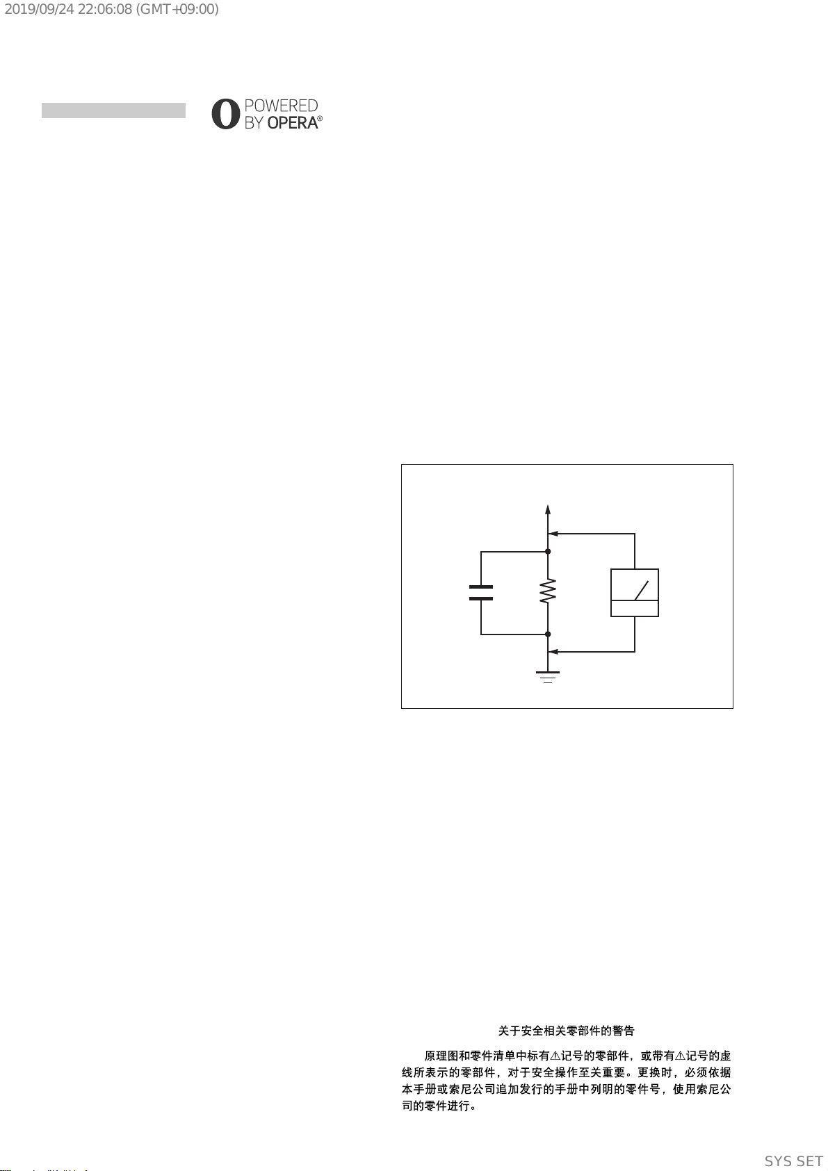
LEAKAGE TEST
The AC leakage from any exposed metal part to earth ground and
from all exposed metal parts to any exposed metal part having a
return to chassis, must not exceed 0.5 mA (500 microamperes.).
Leakage current can be measured by any one of three methods.
1. A commercial leakage tester, such as the Simpson 229 or RCA
WT-540A. Follow the manufacturers’ instructions to use these
instruments.
2. A battery-operated AC milliammeter. The Data Precision 245
digital multimeter is suitable for this job.
3. Measuring the voltage drop across a resistor by means of a
VOM or battery-operated AC voltmeter. The “limit” indication
is 0.75 V, so analog meters must have an accurate low-voltage
scale. The Simpson 250 and Sanwa SH-63Trd are examples
of a passive VOM that is suitable. Nearly all battery operated
digital multimeters that have a 2 V AC range are suitable. (See
Fig. A)
1.5 kΩ0.15 μF
AC
voltmeter
(0.75 V)
To Exposed Metal
Parts on Set
Earth Ground
Fig. A. Using an AC voltmeter to check AC leakage.
This system incorporates Dolby* Digital
and the DTS** Digital Surround System.
* Manufactured under license from Dolby
Laboratories.
Dolby and the double-D symbol are
trademarks of Dolby Laboratories.
**For DTS patents, see http://
patents.dts.com. Manufactured under
license from DTS Licensing Limited. DTS,
DTS-HD, the Symbol, & DTS and the
Symbol together are registered
trademarks of DTS, Inc. © DTS, Inc. All
Rights Reserved.
The BLUETOOTH®word mark and logos are
registered trademarks owned by Bluetooth
SIG, Inc. and any use of such marks by Sony
Corporation is under license. Other
trademarks and trade names are those of
their respective owners.
This system incorporates High-Denition
Multimedia Interface (HDMI™) technology.
The terms HDMI and HDMI High-Denition
Multimedia Interface, and the HDMI Logo
are trademarks or registered trademarks of
HDMI Licensing, LLC in the United States
and other countries.
The N Mark is a trademark or registered
trademark of NFC Forum, Inc. in the United
States and in other countries.
Android, Google Play and Chromecast are
trademarks of Google Inc.
Apple, the Apple logo, iPhone, iPod, iPod
touch, and Retina are trademarks of Apple
Inc., registered in the U.S. and other
countries. App Store is a service mark of
Apple Inc.
“Made for iPod,” and “Made for iPhone”
mean that an electronic accessory has
been designed to connect specically to
iPod or iPhone, respectively, and has been
certied by the developer to meet Apple
performance standards. Apple is not
responsible for the operation of this device
or its compliance with safety and
regulatory standards. Please note that the
use of this accessory with iPod or iPhone
may aect wireless performance.
“BRAVIA” logo is a trademark of Sony
Corporation.
“ClearAudio+” is a trademark of Sony
Corporation.
WALKMAN® and WALKMAN® logo are
registered trademarks of Sony
Corporation.
“PlayStation” is a registered trademark or
trademark of Sony Interactive
Entertainment Inc.
MPEG Layer-3 audio coding technology
and patents licensed from Fraunhofer IIS
and Thomson.
Windows Media is either a registered
trademark or trademark of Microsoft
Corporation in the United States and/or
other countries.
This product is protected by certain
intellectual property rights of Microsoft
Corporation. Use or distribution of such
technology outside of this product is
prohibited without a license from Microsoft
or an authorized Microsoft subsidiary.
Opera® Devices SDK from Opera Software
ASA. Copyright 1995-2016 Opera Software
ASA. All rights reserved.
Wi-Fi®, Wi-Fi Protected Access® and Wi-Fi
Alliance® are registered trademarks of Wi-
Fi Alliance.
Wi-Fi CERTIFIED™, WPA™, WPA2™ and Wi-
Fi Protected Setup™ are trademarks of Wi-
Fi Alliance.
Copyrights and Trademarks
LDAC™ and LDAC logo are trademarks of
Sony Corporation.
LDAC is an audio coding technology
developed by Sony that enables the
transmission of High-Resolution (Hi-Res)
Audio content, even over a Bluetooth
connection. Unlike other Bluetooth
compatible coding technologies such as
SBC, it operates without any down-
conversion of the Hi-Res Audio content*,
and allows approximately three times
more data** than those other technologies
to be transmitted over a Bluetooth wireless
network with unprecedented sound
quality, by means of ecient coding and
optimized packetization.
*excludingDSDformatcontents
**in comparison with SBC (Subband
Coding) when the bitrate of 990 kbps
(96/48 kHz) or 909 kbps (88.2/44.1 kHz) is
selected
This product contains software that is
subject to the GNU General Public License
(“GPL”) or GNU Lesser General Public
License (“LGPL”). These establish that
customers have the right to acquire,
modify, and redistribute the source code of
said software in accordance with the terms
of the GPL or the LGPL.
For details of the GPL, LGPL and other
software licenses, please refer to [Software
License Information] in [System Settings] of
the [Setup] menu on the product.
The source code for the software used in
this product is subject to the GPL and LGPL,
and is available on the Web. To download,
please access the following:
URL:
http://oss.sony.net/Products/Linux
Please note that Sony cannot answer or
respond to any inquiries regarding the
content of this source code.
“DSEE” is a trademark of Sony Corporation.
DLNA™, the DLNA Logo and DLNA
CERTIFIED™ are trademarks, service marks,
or certication marks of the Digital Living
Network Alliance.
“TRILUMINOS” and “TRILUMINOS” logo are
a registered trademark of Sony
Corporation.
This product incorporates Spotify software
which is subject to 3rd party licenses found
here*:
https://developer.spotify.com/esdk-
third-party-licenses/
Spotify andSpotify logos aretrademarks of
the Spotify Group.*
* Depending on the country and region,
this function may not be available.
All other trademarks are trademarks of
their respective owners.
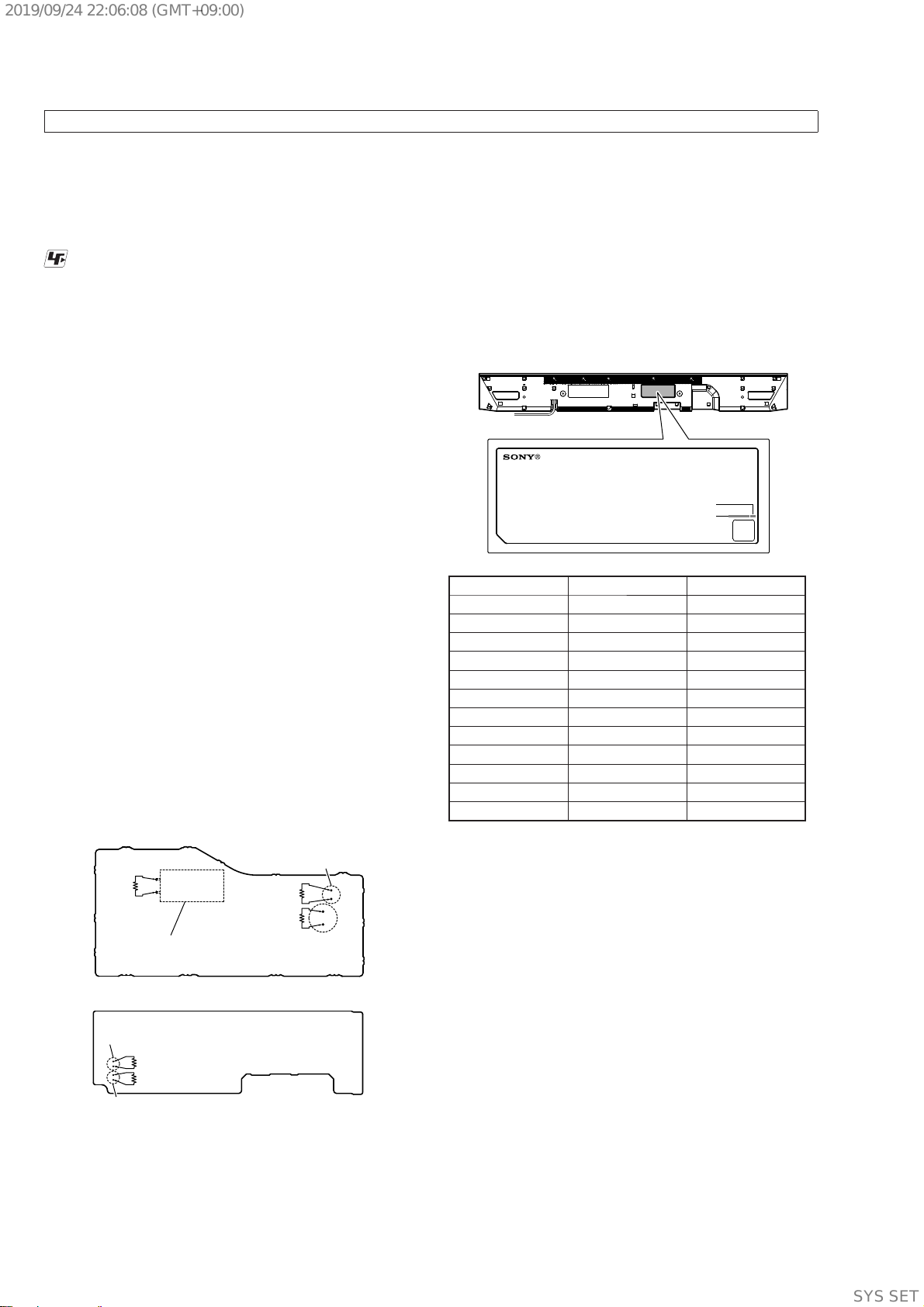
SAFETY-RELATED COMPONENT WARNING!
COMPONENTS IDENTIFIED BY MARK 0OR DOTTED LINE
WITH MARK 0ON THE SCHEMATIC DIAGRAMS AND IN
THE PARTS LIST ARE CRITICAL TO SAFE OPERATION.
REPLACE THESE COMPONENTS WITH SONY PARTS
WHOSE PART NUMBERS APPEAR AS SHOWN IN THIS
MANUAL OR IN SUPPLEMENTS PUBLISHED BY SONY.
ATTENTION AU COMPOSANT AYANT RAPPORT
À LA SÉCURITÉ!
LES COMPOSANTS IDENTIFIÉS PAR UNE MARQUE 0SUR
LES DIAGRAMMES SCHÉMATIQUES ET LA LISTE DES
PIÈCES SONT CRITIQUES POUR LA SÉCURITÉ DE FONC-
TIONNEMENT. NE REMPLACER CES COMPOSANTS QUE
PAR DES PIÈCES SONY DONT LES NUMÉROS SONT DON-
NÉS DANS CE MANUEL OU DANS LES SUPPLÉMENTS
PUBLIÉS PAR SONY.
Ver. 1.1
SYSSET
2019/09/2422:06:08(GMT+09:00)

HT-CT800
3
1. SERVICING NOTES ............................................. 4
2. DISASSEMBLY
2-1. Disassembly Flow........................................................... 9
2-2. Top Cabinet Block .......................................................... 10
2-3. TOUCH Board................................................................ 11
2-4. DISPLAY Board Block................................................... 11
2-5. SIRCS Board................................................................... 12
2-6. DISPLAY Board ............................................................. 12
2-7. Organic EL Indicator Element (OLED1)........................ 13
2-8. Loudspeaker (R-ch) (SP2) .............................................. 14
2-9. Loudspeaker (L-ch) (SP1) .............................................. 15
2-10. USB-CHUKEI Board Block........................................... 16
2-11. USB-CHUKEI Board ..................................................... 17
2-12. NFC Board...................................................................... 17
2-13. BTW (WIFI) Board Block.............................................. 18
2-14. BTW (WIFI) Board......................................................... 19
2-15. BTW (BT) Board Block.................................................. 20
2-16. BTW (BT) Board ............................................................ 21
2-17. WLAN/BT Combo Card (WIFI1) .................................. 22
2-18. Insulation Top Assy......................................................... 23
2-19. Power Cord (AC1) .......................................................... 23
2-20. POWER Board................................................................ 24
2-21. RF Modulator Block ....................................................... 24
2-22. RF Modulator (RF1) ....................................................... 25
2-23. Shield (Main) Block-1 .................................................... 26
2-24. Shield (Main) Block-2 .................................................... 27
2-25. MB-1612 Board .............................................................. 28
2-26. Bottom Chassis Block..................................................... 29
2-27. Service Position (Side A)................................................ 30
2-28. Service Position (Side B)................................................ 30
TABLE OF CONTENTS
3. TEST MODE ............................................................ 31
4. TROUBLESHOOTING .......................................... 40
5. DIAGRAMS
5-1. Block Diagram - HDMI Section -................................... 44
5-2. Block Diagram - MAIN Section -................................... 45
5-3. Block Diagram - AMP Section - ..................................... 46
5-4. Block Diagram
- PANEL/POWER SUPPLY Section -............................ 47
5-5. Printed Wiring Board - MB-1612 Board - ...................... 49
5-6. Printed Wiring Board - USB-CHUKEI Board - ............. 50
5-7. Schematic Diagram - USB-CHUKEI Board - ................ 50
5-8. Printed Wiring Boards - ANTENNA Section -............... 51
5-9. Schematic Diagram - ANTTENA Section -.................... 51
5-10. Printed Wiring Boards - DISPLAY/SIRCS Boards -...... 52
5-11. Schematic Diagram - DISPLAY/SIRCS Boards - .......... 53
5-12. Printed Wiring Board - POWER Board -........................ 54
5-13. Schematic Diagram - POWER Board - .......................... 55
5-14. Printed Wiring Board - TOUCH Board -........................ 56
5-15. Schematic Diagram - TOUCH Board -........................... 56
6. EXPLODED VIEWS
6-1. Overall Section ............................................................... 59
6-2. Top Cabinet Section........................................................ 60
6-3. Bottom Cabinet Section .................................................. 61
6-4. Chassis Section ............................................................... 62
6-5. MAIN Board Section ...................................................... 63
7. ELECTRICAL PARTS LIST .............................. 64
Accessories are given in the last of the electrical parts list.
SYSSET
2019/09/2422:06:08(GMT+09:00)

HT-CT800
4
SECTION 1
SERVICING NOTES
UNLEADED SOLDER
Boards requiring use of unleaded solder are printed with the lead-
free mark (LF) indicating the solder contains no lead.
(Caution: Some printed circuit boards may not come printed with
the lead free mark due to their particular size)
: LEAD FREE MARK
Unleaded solder has the following characteristics.
• Unleaded solder melts at a temperature about 40 °C higher
than ordinary solder.
Ordinary soldering irons can be used but the iron tip has to be
applied to the solder joint for a slightly longer time.
Soldering irons using a temperature regulator should be set to
about 350 °C.
Caution: The printed pattern (copper foil) may peel away if
the heated tip is applied for too long, so be careful!
• Strong viscosity
Unleaded solder is more viscous (sticky, less prone to flow)
than ordinary solder so use caution not to let solder bridges
occur such as on IC pins, etc.
• Usable with ordinary solder
It is best to use only unleaded solder but unleaded solder may
also be added to ordinary solder.
ADVANCE PREPARATION WHEN CONFIRMING OP-
ERATION
Alloftheunitsincluded in theHT-CT800(SA-CT800/SA-WCT800/
Remote control) are required to confirming operation of SA-
CT800. Check in advance that you have all of the units.
CAPACITOR ELECTRICAL DISCHARGE PROCESSING
Before checking the operation of the boards for the electric shock
prevention, perform the discharge processing by connecting the
resistor at both ends of capacitor with referring to the figure below.
Note 1: When the connector that connects the POWER board to the MB-
1612 board is disconnected before discharging, completely fin-
ish discharging both boards, and then reconnect the connector. If
discharging is not complete, sparking may occur when connecting
the connector and cause a blown fuse.
Note 2: Be sure to discharge using a resistor of 800 or higher.
– POWER Board (Conductor Side) –
– MB-1612 Board (Side B) –
C967
C6050
C6068
C970
800 :/2 W
800 :/2 W
C914 (US, CND, E3, EA3, TW)
C915 (AEP, UK, SP1, AR, TH, LA, AUS, CH)
800 :/2 W
800 :/2 W
800 :/2 W
NOTE OF PERFORMING THE OPERATION CHECK IN
THE STATE THAT HEAT SINK IS REMOVED
When performing the operation check in the state that this unit is
disassembled, it is possible to perform the operation check in the
state that heat sink is removed. However, don’t perform the opera-
tion check in the long time, and perform the operation check in the
volume state as low as possible.
The SERVICING NOTES contains important information for servicing. Be sure to read this section before repairing the unit.
“PRTCT”, “PUSH” AND “POWER” FLASH ALTER-
NATELY IN THE FRONT PANEL DISPLAY
qPress Æ(power) to turn off the
system. After the indicator
disappears, disconnect the AC power
cord (mains lead) and make sure
nothing is obstructing the ventilation
holes of the system.
MODEL IDENTIFICATION
Distinguish by Part No. and Destination code of the model number
label on the bottom side of the main unit.
– Bottom view –
MODEL NUMBER LABEL
Destination code
Part No.
Destination Part No. Destination code
US, CND models 4-684-824-0[] UC2
AEP model 4-684-826-0[] CEL
E3 model 4-684-827-0[] E3
TW model 4-690-898-0[] TW2
UK model 4-690-899-0[] CEK
CH model 4-690-900-0[] CN4
TH model 4-690-901-0[] TH1
AR model 4-690-902-0[] AR2
SP1 model 4-690-903-0[] SP1
AUS model 4-690-905-0[] AU1
EA3 model 4-690-906-0[] EA3
LA model 4-690-908-0[] LA9
DESTINATION ABBREVIATIONS
The following abbreviations for model destinations are used in this
service manual.
• Abbreviations
AEP : European (Except for Ireland, UK), Eastern Europe area,
CIS area (Moldova) and Middle East area (Jordan) models
AR : Argentina model
AUS : Australian and New Zealand models
CH : Chinese model
CND : Canadian and Latin American area (Puerto Rico) models
E3 : Middle East area (Lebanon, Syria, Yemen) and African
area (Except for Kenya, Nigeria, Tanzania) models
EA3 : Middle East area (Except for Jordan, Lebanon, Syria, Ye-
men) and African area (Kenya, Nigeria, Tanzania) models
LA : Latin American area (Except for Argentina and Puerto Rico)
model
SP1 : Southeastern Asian area (Except for Thai) and East Asia
area (Hong Kong) models
TH : Thai model
TW : Taiwan model
UK : UK and Ireland models
Ver. 1.3
SYSSET
2019/09/2422:06:08(GMT+09:00)

HT-CT800
5
NOTE OF REPLACING THE MB-1612 BOARD OR
WLAN/BT COMBO CARD
When the MB-1612 board or WLAN/BT combo card is replaced,
be sure to perform with referring to the following item.
When replacing the MB-1612 board:
• NETWORK INFORMATION WRITING METHOD (refer to
this page)
• NETWORK AND NFC CONNECTION CHECKING METH-
OD (refer to page 6)
• NOTICE OF MAC ADDRESS CHANGE TO CUSTOMERS
(refer to page 6)
• WIRELESS CONNECTION (LINK) WORK OF BAR
SPEAKER AND SUBWOOFER (refer to page 7)
When replacing the WLAN/BT combo card:
• NETWORK INFORMATION WRITING METHOD (refer to
this page)
• NETWORK AND NFC CONNECTION CHECKING METH-
OD (refer to page 6)
• NOTICE OF MAC ADDRESS CHANGE TO CUSTOMERS
(refer to page 6)
NETWORK INFORMATION WRITING METHOD
When the MB-1612 board or WLAN/BT combo card is replaced,
perform the writing work of the network information in the service
mode.
Procedure:
1. Connect this unit with TV monitor.
2. Touch the [1] button to turn the power on.
3. Press button on the remote commander in order of the follow-
ing.
[
x] →[DISPLAY] →[X] →[V]
(Make the interval when each button is pressed within one sec-
ond)
4. Enter the service mode. The OSD menu on TV monitor can be
operated by remote commander.
5. Press the [v] button on the remote commander to select
“Diag”, and press the [ ] button on the remote commander.
6. Press the [b] button on the remote commander to select “Wire-
less LAN Test” (refer to Screen 1).
7. Press the [v] button on the remote commander to select “[5]
Write P2P address to Registry”.
8. Press the [ ] button on the remote commander, wait until the
display show “Status: Write Successful!” (refer to Screen 2).
9. Press the [BACK] button on the remote commander to return
to category select screen, and press the [b] button on the re-
mote commander to select “Bluetooth Device Test” (refer to
Screen 3).
10. Press the [ ] button on the remote commander to select “(1)
Bluetooth Enable”.
11. Press the [ ] button on the remote commander, wait until the
display show “Status: Bluetooth Enable Successful!” (refer to
Screen 4).
12. Press the [v] button on the remote commander to select “(3)
Write Bluetooth device address to Registry”.
13. Press the [ ] button on the remote commander, wait until the
display show “Status: Write Successful!” (refer to Screen 5).
14. Touch the [1] button to turn the power off.
Diag
Diag
Category: Wireless LAN Test
[2] Connect to AccessPoint
[3] Start Display RSSI Value
[4] Start Ping Test
P2P device address: 32:52:cb:15:e7:95
HELP: [UP] [DOWN] [ENT] [RET]
Status: Write Successful!
(Screen 1)
(Screen 2)
Category: Wireless LAN Test
[1] Show WLAN HwInfo
(Screen 5)
Status: Write Successful!
Diag
Category: Bluetooth Device Test
(2) Bluetooth Disable
(3) Write Bluetooth device address to Registry
(4) Bluetooth Inquiry Test
Bluetooth Device address: 32:52:CB:15:E7:95
HELP: [UP] [DOWN] [ENT] [RET]
(1) Bluetooth Enable
[5] Write P2P address to Registry
[6] P2P Registry Check
Diag
Diag
Category: Bluetooth Device Test
(2) Bluetooth Disable
(3) Write Bluetooth device address to Registry
(4) Bluetooth Inquiry Test
HELP: [UP] [DOWN] [ENT] [RET]
(Screen 3)
(Screen 4)
Category: Bluetooth Device Test
(1) Bluetooth Enable
Status: Bluetooth Enable Successful!
SYSSET
2019/09/2422:06:08(GMT+09:00)

HT-CT800
6
NETWORK AND NFC CONNECTION CHECKING METH-
OD
When the MB-1612 board or WLAN/BT combo card is replaced,
check the connection of wireless/wired LAN and NFC.
1. Checking method of wireless LAN connection
Necessary equipment:
• TV monitor
• Access point supporting WPS
Procedure:
1. Connect this unit with TV monitor.
2. Touch the [1] button to turn the power on.
3. Press the [HOME] button on the remote commander, display
the home screen.
4. Press the [V]/[v] buttons on the remote commander to select
the “ Setup”, and press the [ ] button on the remote com-
mander.
5. Press the [V]/[v] buttons on the remote commander to select
the “Network Settings”, and press the [ ] button on the remote
commander.
6. Press the [V]/[v] buttons on the remote commander to select
the “Internet Settings”, and press the [ ] button on the remote
commander.
7. Press the [V]/[v] buttons on the remote commander to select
the “Wireless Setup”, and press the [ ] button on the remote
commander.
8. Press the [V]/[v] buttons on the remote commander to select
the “Wi-Fi Protected Setup™ (WPS)”, and press the [ ] but-
ton on the remote commander.
9. The message “Start” is displayed.
10. Press the [ ] button on the remote commander, and press the
[WPS] button on the access point.
11. When wireless LAN connection is completed, “Wireless Con-
nection: OK” and “Internet Access: OK” is displayed.
Note: Refer to the Operating Instructions about details of the connection
method.
2. Checking method of wired LAN connection
Necessary equipment:
• TV monitor
• Router
• Network LAN cable
Procedure:
1. Connect this unit with TV monitor.
2. Connect this unit to the router with the network LAN cable.
3. Touch the [1] button to turn the power on.
4. Press the [HOME] button on the remote commander, display
the home screen.
5. Press the [V]/[v] buttons on the remote commander to select
the “ Setup”, and press the [ ] button on the remote com-
mander.
6. Press the [V]/[v] buttons on the remote commander to select
the “Network Settings”, and press the [ ] button on the remote
commander.
7. Press the [V]/[v] buttons on the remote commander to select
the “Internet Settings”, and press the [ ] button on the remote
commander.
8. Press the [V]/[v] buttons on the remote commander to select
the “Wired Setup”, and press the [ ] button on the remote
commander.
9. Press the [V]/[v] buttons on the remote commander to select
the “Auto”, and press the [b] button on the remote command-
er.
10. The “The network will be configured with the following set-
tings” screen is display, and press the [b] button on the remote
commander.
11. Press the [V]/[v] buttons on the remote commander to select
the “Save & Connect”, and press the [ ] button on the remote
commander.
12. When wired LAN connection is completed, “Physical Connec-
tion: OK” and “Internet Access: OK” is displayed.
Note: Refer to the Operating Instructions about details of the connection
method.
3. Checking method of NFC connection
Necessary equipment:
• NFC-compatible mobile device such as a smartphone, tablet or
music player
(OS: Android™ 2.3.3 or later, excluding Android 3.x)
Procedure:
1. Touch the [1] button to turn the power on.
2. Touch the N mark on this unit with the mobile device.
BLUETOOTH indicator
– Front view –
3. Make sure that the BLUETOOTH indicator lights in blue.
(A connection between the system and mobile device has been
established)
4. Start audio playback with the music application on the con-
nected mobile device.
Note: After checking of NFC connection, be sure to delete the pairing
information before returning this unit to the customer.
NOTICE OF MAC ADDRESS CHANGE TO CUSTOM-
ERS
When the MB-1612 board or WLAN/BT combo card is replaced,
the MAC address has been changed.
Print the following explanations, and pass it to the customer with
the repaired unit when returning the customer repaired unit.
Note of the MAC address change:
The MAC address of this unit was changed along with this repair.
Please set it again if you are using the MAC address filtering function
of access point device of connection destination.
MAC address can be confirmed from the settings menu screen of this
unit. Please refer to the “Using the Various Functions/Settings” of Op-
erating Instructions for details.
SYSSET
2019/09/2422:06:08(GMT+09:00)

HT-CT800
7
INITIALIZING METHOD
It can return all settings to the initial state of factory shipment.
Note 1: Disconnect the following connections when using this mode.
USB
LAN
HDMI IN 1
HDMI IN 2
HDMI IN 3
Note 2: The operation in this mode must use the remote commander and
TV monitor.
Procedure:
1. Connect this unit with TV monitor.
2. Touch the [1] button to turn the power on
3. Press the [HOME] button on the remote commander, and the
home menu is displayed.
4. Press the [V]/[v] buttons on the remote commander to select
the “ Setup”, and press the [ ] button on the remote com-
mander.
5. Press the [V]/[v] buttons on the remote commander to select
the “Resetting”, and press the [ ] button on the remote com-
mander.
6. Select “Reset to Factory Default Settings”, and press the [ ]
button on the remote commander.
7. Press the [V]/[v] buttons on the remote commander to select
the “All Settings”, and press the [ ] button on the remote com-
mander.
8. Press the [B]/[b] buttons on the remote commander to select
the “Start”, and press the [ ] button on the remote commander.
9. Turn the power off automatically, and initialization ends.
Note 3: By perform resetting, the link with the subwoofer may be lost. In
this case, refer to “WIRELESS CONNECTION (LINK) WORK
OF BAR SPEAKER AND SUBWOOFER” on this page.
NOTE OF REPLACING THE NFC BOARD FOR RE-
PAIRING
When the NFC board is defective, replace the complete mounted
board.
The mounted parts cannot be replaced with single for repairing.
NOTE OF REPAIRING THE MB-1612 BOARD
Among mounted parts on the MB-1612 board, only parts that are
described in the electrical parts list can be replaced for repair.
When the parts that are not described in the electrical parts list are
defective, replace the complete mounted board.
In this service manual, the schematic diagram of the MB-1612
board is not described.
NOTE OF REPLACING THE ELECTRICAL PARTS ON
EACH BOARDS FOR REPAIRING
Among mounted electrical parts on each boards, only parts that
are described in the electrical parts list can be replaced for repair.
The parts that are not described in the electrical parts list cannot be
replaced with single for repairing.
WIRELESS CONNECTION (LINK) WORK OF BAR SPEAK-
ER AND SUBWOOFER
When the parts below is replaced, the wireless connection (LINK)
of the Bar speaker and Subwoofer will be disconnected.
Before returning repaired products to the customer, follow the pro-
cedure below to LINK the Bar speaker and Subwoofer.
Also, if only the Bar speaker or Subwoofer is brought in for repair
and the parts below are replaced, be sure to inform the customer
when returning the repaired products that the customer must LINK
the Bar speaker and Subwoofer.
(Indicate that the LINK procedure is described in the operating
instructions)
Parts in which the LINK will be disconnected due to re-
placement:
• MB-1612 board
• RF modulator (SWA12-4V TX)
Link method:
1Press HOME.
The home menu appears on the TV
screen.
2Select [Setup] from the home
menu.
The setup display appears on the TV
screen.
3Select [System Settings] -
[Wireless Subwoofer Connection].
The [Wireless Subwoofer
Connection] screen appears on the
TV screen.
LINK
Power indicator
4Press LINK on the rear of the
subwoofer.
The power indicator of the
subwoofer flashes in green.
Proceed to the next step within 1
minute.
5Select [Start].
The link setting starts.
To return to the previous display,
select [Cancel].
6Complete the link setting by
following the on-screen message.
The power indicator of the
subwoofer lights in green.
• If the message [Cannot set Link.] appears,
follow the on-screen instructions.
• When [Bluetooth Mode] is set to
[Transmitter] and the BLUETOOTH device
is connected to the system, the wireless
subwoofer connection cannot be
established.
Notes
SYSSET
2019/09/2422:06:08(GMT+09:00)

HT-CT800
8
BOND FIXED POSITION OF ELECTRICAL PARTS
When the parts that fixed on the board by the bond have been removed, fix the parts by using the bond (ADHESIVE (SC608Z2)) in the
mounting to the board. (Refer to the figure below)
[ ]: Bond application portion
– POWER Board
(Component Side) –
C914 or C915
C941
C935 or C938
C967
F931 T901
C976
C970 C977
C969
C980
T901 T901
R914
C914 or C915
D901
C905
TH901
C907 or C988
LF901
VDR901
R944
– MB-1612 Board (Side A) –
C6068C6050
ET306
ET308
ET303
ET302
ET304
Adhesion of the
bond to this place
is prohibited.
CONTACT
TERMINAL
C902 or C989 C903 or C990
Note: Please use the bond of low viscosity in the
bond to be used to ET302, ET303, ET304,
ET306 and ET308. These are different
from the bond to be used for other parts.
Also a contact surface (refer to left figure)
of the CONTACT TERMINAL, be careful
absolutely bond does not adhere.
MALFUNCTION PREVENTION OF THE BUTTON (TOUCH
PANEL SWITCH)
When the button portion on the top side of the main unit are
touched with something such as the floor surface, there is a pos-
sibility of occurring the malfunction.
When performing the operation check in the state that the top side
on this unit is under, set the stand etc. to the position that avoids the
button portion as shown in the figure below, perform in the state
that the button portion does not touch anything.
bottom side
stand stand
button portion
SPREADING OF COMPOUND
When the IC6005 on the MB-1612 board or the MB-1612 board is
replaced, spread the compound to the touching portion between the
IC6005 and the heat sink.
– MB-1612 Board (Side A) –
IC6005
compound
SYSSET
2019/09/2422:06:08(GMT+09:00)

HT-CT800
9
SECTION 2
DISASSEMBLY
• This set can be disassembled in the order shown below.
2-1. DISASSEMBLY FLOW
SET
2-23. SHIELD (MAIN) BLOCK-1
(Page 26)
2-28. SERVICE POSITION (SIDE B)
(Page 30)
2-27. SERVICE POSITION (SIDE A)
(Page 30)
2-19. POWER CORD (AC1)
(Page 23)
2-26. BOTTOM CHASSIS BLOCK
(Page 29)
2-2. TOP CABINET BLOCK
(Page 10)
2-3. TOUCH BOARD
(Page 11)
2-4. DISPLAY BOARD BLOCK
(Page 11)
2-8. LOUDSPEAKER (R-CH) (SP2)
(Page 14)
2-9. LOUDSPEAKER (L-CH) (SP1)
(Page 15)
2-5. SIRCS BOARD
(Page 12)
2-6. DISPLAY BOARD
(Page 12)
2-7. ORGANIC EL INDICATOR ELEMENT (OLED1)
(Page 13)
2-12. NFC BOARD
(Page 17)
2-17. WLAN/BT COMBO CARD (WIFI1)
(Page 22)
2-18. INSULATION TOP ASSY
(Page 23)
2-10. USB-CHUKEI BOARD BLOCK
(Page 16)
2-11. USB-CHUKEI BOARD
(Page 17)
2-13. BTW (WIFI) BOARD BLOCK
(Page 18)
2-15. BTW (BT) BOARD BLOCK
(Page 20)
2-14. BTW (WIFI) BOARD
(Page 19)
2-16. BTW (BT) BOARD
(Page 21)
2-20. POWER BOARD
(Page 24)
2-21. RF MODULATOR BLOCK
(Page 24)
2-22. RF MODULATOR (RF1)
(Page 25)
2-24. SHIELD (MAIN) BLOCK-2
(Page 27)
2-25. MB-1612 BOARD
(Page 28)
SYSSET
2019/09/2422:06:08(GMT+09:00)

HT-CT800
10
Note: Follow the disassembly procedure in the numerical order given.
2-2. TOP CABINET BLOCK
Note 1: Lay a soft piece of cloth under the unit
to avoid damaging the top cabinet assy.
1twelve screws
(BVTP3 u8)
bottom cabinet block
rear side
bottom side
right side
1twelve screws
(BVTP3 u8)
3FFC 18P
(CN5003)
terminal side
2Open the top cabinet block
in the direction of the arrow.
right side
rear side
6top cabinet block
top side
Note 2: Take care not to crush
the front grille.
5R-ch speaker cable
connector (CN6003)
4L-ch speaker cable
connector (CN6002)
guide line
top cabinet block
top side
L-ch speaker cable
R-ch speaker cable
rear side
6SHDNHUFDEOHVHWWLQJ
left side
SYSSET
2019/09/2422:06:08(GMT+09:00)

HT-CT800
11
2-3. TOUCH BOARD
2-4. DISPLAY BOARD BLOCK
3FFC 6P
(CN1901)
FFC 6P
rear side
right side
4W-adhesive
tape
W-adhesive tape W-adhesive tape
5TOUCH board TOUCH
board
TOUCH board TOUCH board
2Peel off the TOUCH
board block.
1filament tape
(sub material)
filament tape
(sub material)
terminal
side
top cabinet block
Note 2: Take care not to crush
the front grille.
Note 1: Lay a soft piece of cloth under the unit
to avoid damaging the top cabinet assy.
3DVWLQJSRVLWLRQRIWKHILODPHQWWDSH
VXEPDWHULDO
$IIL[LQJWKH:DGKHVLYHWDSH
front side
OK NG
right side
2two screws
(PTP2 u5)
rear side
right side
top cabinet block
3
5DISPLAY board block
DISPLAY board
Note 1: Lay a soft piece of cloth under the unit
to avoid damaging the top cabinet assy.
Note 2: Take care not to crush
the front grille.
terminal
side
1filament tape
(sub material)
filament tape
(sub material)
4FFC 6P
(CN1301)
front side
FFC 6P
3DVWLQJSRVLWLRQRIWKHILODPHQWWDSH
VXEPDWHULDO
right side
SYSSET
2019/09/2422:06:08(GMT+09:00)

HT-CT800
12
2-5. SIRCS BOARD
2-6. DISPLAY BOARD
top side
left side
right side
Bend the wire.
:LUHVHWWLQJ
bottom side
hook
SIRCS board
DISPLAY board block
2claw
3
rib
groove
4SIRCS board
Note: When installing the SIRCS board,
align the groove and rib.
1DISPLAY board
cable connector
(CN891)
–5HDUYLHZ–
:LUHVHWWLQJ
bottom side
right side
DISPLAY board block
boss
boss
hole
groove
3two screws
(PTP2 u5)
9FFC 18P
(CN1303)
1connector
(CN891) hook
2Remove the wire
from the hook.
4Open the DISPLAY board block
in the direction of the arrow.
8connector
(CN1304)
terminal
side
0DISPLAY board
Note: When installing the DISPLAY board, align
the groove and hole with the two bosses.
5Unlock
CN1302
Bend the wire.
hook
SIRCS board
bottom side
terminal side
6Insert a tweezers etc. in
the hole of the FPC.
tweezers etc.
hole
7Pull out the FPC from the
connector horizontally.
FPC
SYSSET
2019/09/2422:06:08(GMT+09:00)

HT-CT800
13
2-7. ORGANIC EL INDICATOR ELEMENT (OLED1)
top side
right side
left side
DISPLAY bracket block
2Peel the organic EL indicator
element off of the adhesive sheet.
3organic EL indicator element
(OLED1)
1cushion (OLED)
SYSSET
2019/09/2422:06:08(GMT+09:00)

HT-CT800
14
2-8. LOUDSPEAKER (R-CH) (SP2)
255 mm
Note 3: When connecting the terminals of the
connection cable to the loudspeaker, be
careful of the direction of the terminals.
loudspeaker (R-ch)
5two screws
(BVTP3.5)
6loudspeaker
(R-ch) (SP2)
loudspeaker (R-ch) (SP2)
3 terminal (wide)
[red]
wide
3 terminal (narrow)
[black]
narrow
1 Draw the connection cable
out of the two grooves.
2 Draw the connection cable
out of the groove.
1 Draw the connection cable
out of the two grooves.
,QVWDOODWLRQGLUHFWLRQZKHQFRQQHFWLQJWKH
WHUPLQDOVRIWKHFRQQHFWLRQFDEOH5FK
,QVWDOODWLRQGLUHFWLRQIRUWKH
ORXGVSHDNHU5FK63
Note 1: Lay a soft piece of cloth under the unit
to avoid damaging the top cabinet assy.
rear side
rear side
right side
right side
,QVWDOODWLRQSRVLWLRQRIWKHSDFNLQJ&/
&RQQHFWLRQFDEOH5FKVHWWLQJ
5screw
(BVTP3.5)
5screw
(BVTP3.5)
top cabinet block
groove groove groove groove groove
packing (CL3)
packing (CL3) [red]
[black]
loudspeaker (R-ch) (SP2)
right side
4connection cable block (R-ch)
front side
Note 2: Take care not to crush
the front grille.
OK
NG
OK
NG
packing (CL3)
SYSSET
2019/09/2422:06:08(GMT+09:00)

HT-CT800
15
2-9. LOUDSPEAKER (L-CH) (SP1)
270 mm
loudspeaker (L-ch)
5two screws
(BVTP3.5)
6loudspeaker
(L-ch) (SP1)
3 terminal (wide)
[gray]
3 terminal (narrow)
[black]
2 Draw the connection cable
out of the groove.
Note 1: Lay a soft piece of cloth under the unit
to avoid damaging the top cabinet assy.
packing
(CL3)
5screw
(BVTP3.5)
5screw
(BVTP3.5)
top cabinet block
2
4
3
5
1
4connection
cable block
(L-ch)
rear side
left side
1tape
1two
tapes
,QVWDOODWLRQSRVLWLRQRIWKHSDFNLQJ&/
&RQQHFWLRQFDEOH/FKVHWWLQJ
groove
packing (CL3)
packing (CL3)
[gray]
[black]
loudspeaker (L-ch)
(SP1)
left side
tape two tapes
Press.
front side
Note 2: Take care not to crush
the front grille.
loudspeaker (L-ch) (SP1)
wide
narrow
,QVWDOODWLRQGLUHFWLRQIRUWKH
ORXGVSHDNHU/FK63
rear side
left side
OK
NG
OK
NG
Note 3: When connecting the terminals of the
connection cable to the loudspeaker, be
careful of the direction of the terminals.
,QVWDOODWLRQGLUHFWLRQZKHQFRQQHFWLQJWKH
WHUPLQDOVRIWKHFRQQHFWLRQFDEOH/FK
SYSSET
2019/09/2422:06:08(GMT+09:00)

HT-CT800
16
2-10. USB-CHUKEI BOARD BLOCK
front side
right side
1Remove the two USB-CHUKEI board
cables from the wiring stopper.
3leaf spring
3leaf spring
3leaf spring
6FFC 6P
(CN1453)
3leaf spring
0two
claws
4screw
(BVTP3 u8)
4screw
(BVTP3 u8) 5wire 9cushion
(CL3)
terminal side
groove
claw
leaf spring
slit
flathead screwdriver
:LUHVHWWLQJ
front side
right side
leaf spring
leaf spring
leaf spring
leaf spring USB-CHUKEI board
7connector
(CN501)
8connector
(CN5004)
bottom cabinet block
rib
2Insert a flathead screwdriver, etc. into
the slit, and slide the leaf spring in the
direction of the arrow while pushing
the claw to remove the leaf spring.
qa USB-CHUKEI board block
Note: When installing the
USB-CHUKEI board
block, align the rib
and groove.
wiring stopper
Pass the USB-CHUKEI board
cable between the RF modulator
and shield (main).
shield (main)
RF modulator
USB-CHUKEI
board cable
CN501
WLAN/BT combo
card cable
rear side
:LUHVHWWLQJ
CN5004
black line
SYSSET
2019/09/2422:06:08(GMT+09:00)

HT-CT800
17
2-11. USB-CHUKEI BOARD
2-12. NFC BOARD
7USB-CHUKEI board
4connector
(CN1451)
1connector
(CN1401)
3cushion (CZ2-A)
6cushion (T03)
6cushion (T03)
6cushion (T03)
white line
cushion (T03)
cushion (T03)
cushion (T03)
guide line
guide line
:LUHVHWWLQJ
3DVWLQJSRVLWLRQRIWKHFXVKLRQ7
,QVWDOODWLRQGLUHFWLRQIRUWKH0%ERDUGFRQQHFWLRQFDEOH3
2MB-1612 board
connection cable
(5P)
10 mm
–5HDUYLHZ–
Note 1: Arrange the cable along the white
line on the USB-CHUKEI board.
Note 2: When affixing the cushion (CZ2-A),
be careful that it does not obstruct
the screw hole.
USB-CHUKEI board
USB-CHUKEI board
screw hole
1 mm
to MB-1612 board to USB-CHUKEI board
–5HDUYLHZ–
guide line
cushion
(CZ2-A)
MB-1612 board
connection cable
(6P)
5MB-1612 board
connection cable
(6P)
front side
right side
2FFC 6P
(CN001)
terminal
side
bottom cabinet block 4NFC board
3double adhesive tape
rear side
right side
FFC 6P
rib
NFC board
USB-CHUKEI board
))&VHWWLQJ
1Peel the NFC board
block off of the bottom
cabinet block.
SYSSET
2019/09/2422:06:08(GMT+09:00)

HT-CT800
18
2-13. BTW (WIFI) BOARD BLOCK
front side
3three screws
(BVTP3 u8)
4BTW (WIFI) board block
bottom cabinet block
left side
1cushion (WIFI label)
2connector (No. 3)
[gray]
2connector (No. 2)
[white]
3DVWLQJSRVLWLRQRIWKHFXVKLRQ:,),ODEHO
guide line
guide line
Pressing the adhesive area.
cushion (WIFI label)
&RD[LDOKDUQHVV>ZKLWH@>JUD\@VHWWLQJ
front side
left side
BTW (WIFI-1) board
[white]: No. 2
Pass the coaxial harness
across the front side of
the screw hole.
[gray]: No. 3
BTW (WIFI-2) board
slot slot
front side
Pass the coaxial harness
across the front side of
the screw hole.
Pass the coaxial harness
across the front side of
the screw hole.
Note: This part is deleted from
the midway of production.
Ver. 1.3
SYSSET
2019/09/2422:06:08(GMT+09:00)

HT-CT800
19
2-14. BTW (WIFI) BOARD
6 ± 3 mm 6 ± 3 mm265 mm
6 ± 3 mm 6 ± 3 mm325 mm
,QVWDOODWLRQGLUHFWLRQIRUWKH%7::,),ERDUGDQGDQWHQQDKROGHU front side
left side
right side
Triangle shape.
marking marking
marking
Triangle shape. Triangle shape.
Upward arrow. Upward arrow.
3coaxial harness
block [gray]
3coaxial harness
block [white]
2connector
[gray]
2connector
[white]
coaxial harness
[gray] coaxial harness
[white]
1antenna holder
1antenna holder
1antenna holder
4BTW (WIFI-2) board
4BTW (WIFI-1) board
top side
left side
right side
3DVWLQJSRVLWLRQRIWKHFXVKLRQ7
coaxial harness [gray]
coaxial harness [white] cushion (T03)
cushion (T03)
3DVWLQJSRVLWLRQRIWKHFXVKLRQ7
BTW (WIFI-1) board BTW (WIFI-2) board
front side
rear side
rear side
SYSSET
2019/09/2422:06:08(GMT+09:00)

HT-CT800
20
2-15. BTW (BT) BOARD BLOCK
1cushion (WIFI label)
3two screws
(BVTP3 u8)
4BTW (BT) board block
2connector (No. 1)
[black]
front side
right
side
bottom cabinet block
[black]: No. 1
&RD[LDOKDUQHVV>EODFN@VHWWLQJ
Pass the coaxial harness
across the rear side of
the screw hole.
Pass the coaxial harness
across the front side of
the screw hole.
slit
rib
rib
rib
front side
right side
3DVWLQJSRVLWLRQRIWKHFXVKLRQ:,),ODEHO
guide line
guide line
Pressing the adhesive area.
cushion (WIFI label)
slot
BTW (BT) board
front side
Pass the coaxial harness
across the rear side of
the screw hole.
Note: This part is deleted from
the midway of production.
Ver. 1.3
SYSSET
2019/09/2422:06:08(GMT+09:00)
Other manuals for HT-CT800
5
This manual suits for next models
1
Table of contents
Other Sony Speakers System manuals

Sony
Sony SS-GN800 User manual

Sony
Sony SRS-Z30 User manual

Sony
Sony SRS-Z500 User manual

Sony
Sony SS-AR1 User manual

Sony
Sony HTG700CEK User manual

Sony
Sony SRS-Z750 User manual

Sony
Sony CMT-ED1 - Micro Hi Fi Component System User manual

Sony
Sony SS-GT4DB User manual

Sony
Sony SA-WMS345 User manual

Sony
Sony SRS-Z750 User manual