Sony SS-CT150 User manual

SERVICE MANUAL
Sony Corporation
Audio&Video Business Group
Published by Sony Techno Create Corporation
SS-CT150/CT350
SPECIFICATIONS
SPEAKER SYSTEM
9-889-811-01
2010C05-1
© 2010.03
US Model
Canadian Model
SS-CT150/CT350
AEP Model
UK Model
SS-CT350
Ver. 1.0 2010.03
• SS-CT150 is the speaker system in HT-CT150.
• SS-CT350 is the speaker system in HT-CT350.
• When the operation of the active subwoofer (SA-WCT150/
WCT350) or satellite speaker (SS-CT150/CT350) is confirmed,
it is necessary to connect both these set.
Confirm the active subwoofer (SA-WCT150/WCT350) and
satellite speaker (SS-CT150/CT350) are prepared beforehand
when you repair.
Speaker (SS-CT150)
Front speaker unit
Speaker system Full range, Bass reflex
Speaker units 50 mm × 90 mm (2 in ×
3 5/8in) cone type
Rated impedance 4 ohms
Center speaker unit
Speaker system Full range, Bass reflex
Speaker units 50 mm × 90 mm (2 in ×
3 5/8in) cone type
Rated impedance 4 ohms
Dimensions (approx.) 800 mm × 66 mm × 60 mm
(31 1/2in × 2 5/8in ×
2 3/8in) (w/h/d)
Mass (approx.) 1.3 kg (2 lb 14 oz)
Speaker (SS-CT350)
Front speaker unit
Speaker system Full range
Speaker unit 40 mm × 70 mm (1 5/8 in ×
2 7/8 in), cone type × 2
Rated impedance 4 ohms
Center speaker unit
Speaker unit 40 mm (1 5/8 in), cone type
× 2
Rated impedance 4 ohms
Dimensions (approx.) 996 mm × 66 mm × 72 mm
(39 1/4 in × 2 5/8 in × 2 7/8
in) (w/h/d)
Mass (approx.) 2.4 kg (5 lb 5 oz)
Speaker cords 3 m
Design and specifications are subject to change without
notice.
Photo: SS-CT150
Photo: SS-CT350

SS-CT150/CT350
2
SECTION 1
SERVICING NOTES
UNLEADED SOLDER
Boards requiring use of unleaded solder are printed with the lead-
free mark (LF) indicating the solder contains no lead.
(Caution: Some printed circuit boards may not come printed with
the lead free mark due to their particular size)
: LEAD FREE MARK
Unleaded solder has the following characteristics.
• Unleaded solder melts at a temperature about 40 °C higher
than ordinary solder.
Ordinary soldering irons can be used but the iron tip has to be
applied to the solder joint for a slightly longer time.
Soldering irons using a temperature regulator should be set to
about 350 °C.
Caution: The printed pattern (copper foil) may peel away if
the heated tip is applied for too long, so be careful!
• Strong viscosity
Unleaded solder is more viscous (sticky, less prone to flow)
than ordinary solder so use caution not to let solder bridges
occur such as on IC pins, etc.
• Usable with ordinary solder
It is best to use only unleaded solder but unleaded solder may
also be added to ordinary solder.
ADVANCE PREPARATION WHEN CONFIRMING OP-
ERATION
When the operation of the subwoofer (SA-WCT150/WCT350) or
satellite speaker (SS-CT150/CT350) is confirmed, it is necessary
to connect both these set.
Confirm the subwoofer (SA-WCT150/WCT350) and satellite
speaker (SS-CT150/CT350) are prepared beforehand when you
repair.
NOTE OF SS-CT150 DISASSEMBLING
Cutting of cloth grille is necessary for disassembling SS-CT150.
When assembling, exchange cloth grille and frame grille for new
grille frame assy.
• JIG
When disassembling the set, use the following jig (for speaker
removal).
Part No. J-2501-238-A JIG FOR SPEAKER REMOVAL

SS-CT150/CT350
3
SECTION 2
DISASSEMBLY
• This set can be disassembled in the order shown below.
2-1. DISASSEMBLY FLOW
Note: Follow the disassembly procedure in the numerical order given.
2-2. FRAME GRILLE (SS-CT150)
Note 1: Please set as shown in figure and work.
Note 2: When assembling, exchange cloth grille and frame grille for new grille frame assy.
SET
2-2. FRAME GRILLE (SS-CT150)
(Page 3)
2-3. GRILLE FRAME ASSY (SS-CT350)
(Page 4)
bottom side
total twelve bosses
1 Cut the cloth grille with cutter etc..
cutter
etc.
grille frame assy
cloth grille
3
4 frame grille
Note 4: Frame grille cannot re-used.
2 cloth grille
Note 3: Cloth grille cannot re-used.

SS-CT150/CT350
4
2-3. GRILLE FRAME ASSY (SS-CT350)
Note 1: Please set as shown in figure and work.
bottom side
total twenty-six bosses
total four slits
1 Insert a flat-head screwdriver into
a recess in the bottom of the set
to raise the grille frame assy a little.
1
1
1
2
3
3
3
4
3 All bosses are removed while
moving jig in the direction of
the arrow, and grille frame assy
is removed.
5 grille frame assy
grille frame assy
2 Insert the jig (Part No. J-2501-238-A) into a space
and raise the grille frame assy gradually.
Note 2: When using a jig, please work so as not
to injure grille frame assy and speaker
cabinet assy.

SS-CT150/CT350
5
For Schematic Diagrams.
Note:
• C: Panel designation.
• Signal path.
F: AUDIO
THIS NOTE IS COMMON FOR PRINTED WIRING BOARDS AND SCHEMATIC DIAGRAMS.
(In addition to this, the necessary note is printed in each block.)
For Printed Wiring Boards.
Note:
• X: Parts extracted from the component side.
• : Pattern from the side which enables seeing.
(The other layers’ patterns are not indicated.)
SECTION 3
DIAGRAMS
3-1. PRINTED WIRING BOARD - SS-SPEAKER Board -
3-2. SCHEMATIC DIAGRAM - SS-SPEAKER Board -
• : Uses unleaded solder.
JL891
JL893
JL894
JL895
JL896
JL897
137
TB891
TB892
CN892
CENTER
LR
1-881-169-
11
(11)
SS-SPEAKER BOARD
(FRONT R-ch)
SP891
(CENTER)
SP894
(CENTER)
SP893
(FRONT L-ch)
SP896
(CT350)
(CT350)
(CT350)
(FRONT L-ch)
SP895
A
B
C
1 2 3
(FRONT R-ch)
SP892
JL897
JL893
JL891
JL896
(+)
(-)
(+)
(-)
TB891
JL895
JL894
(-)
(+)
TB892
1
3
4
5
6
7
7P
CN892
FR-
FR+
2NC
C-
C+
FL-
FL+
L
CENTER
R
SS-SPEAKER BOARD
SP893
(CENTER)
SP895
(FRONT L-ch)
SP892
(FRONT R-ch)
SP896
(FRONT L-ch)
4
B
351
A
2
SP891
(FRONT R-ch)
(CT350)
(CT350)
(CT350)
SP894
(CENTER)

6
SS-CT150/CT350
SECTION 4
EXPLODED VIEWS
1 A-1744-565-A GRILLE FRAME ASSY
2 4-986-971-02 SCREW (3.5)
3 4-161-599-01 PANEL, FRONT
4 4-986-971-12 SCREW (3.5)
5 1-837-277-11 CORD WITH CONNECTOR
6 A-1744-564-A SPEAKER CABINET ASSY
7 2-653-226-01 KEY HOLE SEALED CAP
8 2-893-646-01 FOOT
SP891 1-858-312-11 LOUDSPEAKER (5X9 cm) (FRONT R-ch)
SP893 1-858-312-11 LOUDSPEAKER (5X9 cm) (CENTER)
SP895 1-858-312-11 LOUDSPEAKER (5X9 cm) (FRONT L-ch)
#1 7-685-648-79 SCREW +BVTP 3X12 TYPE2 IT-3
Ref. No. Part No. Description Remark Ref. No. Part No. Description Remark
Note:
• -XX and -X mean standardized parts, so
they may have some difference from the
original one.
• Items marked “*” are not stocked since
they are seldom required for routine ser-
vice. Some delay should be anticipated
when ordering these items.
• The mechanical parts with no reference
number in the exploded views are not sup-
plied.
• Color Indication of Appearance Parts Ex-
ample:
KNOB, BALANCE (WHITE) . . . (RED)
↑↑
Parts Color Cabinet’s Color
4-1. SS-CT150
2
3
4
5
not supplied
1
not
supplied
not
supplied
not supplied
not supplied
not supplied
SP895
SP893
SP891
4
4
8
7
6
#1
not supplied
(SS-SPEAKER board)

7
SS-CT150/CT350
4-2. SS-CT350
51 A-1761-084-A GRILLE FRAME ASSY
52 4-986-971-02 SCREW (3.5)
53 4-986-971-12 SCREW (3.5)
54 A-1760-737-A CABINET ASSY
55 4-235-399-01 CATCHER
56 4-174-685-01 COVER REAR
57 2-580-608-01 SCREW, +PSW M5X16
58 4-174-974-01 LABEL TERMINAL
59 4-972-322-01 FOOT (Y) (4 pieces, 1 set)
60 1-837-277-21 CORD WITH CONNECTOR
SP891 1-858-376-11 LOUDSPEAKER (4X7 cm) (FRONT R-ch)
SP892 1-858-376-11 LOUDSPEAKER (4X7 cm) (FRONT R-ch)
SP893 1-858-377-11 LOUDSPEAKER (4 cm) (CENTER)
SP894 1-858-377-11 LOUDSPEAKER (4 cm) (CENTER)
SP895 1-858-376-11 LOUDSPEAKER (4X7 cm) (FRONT L-ch)
SP896 1-858-376-11 LOUDSPEAKER (4X7 cm) (FRONT L-ch)
#1 7-685-648-79 SCREW +BVTP 3X12 TYPE2 IT-3
Ref. No. Part No. Description Remark Ref. No. Part No. Description Remark
52
52
51
55
56 57
59
60
53
54
#1
52
53
53
53
53
53
58
not supplied
not supplied
not supplied
not supplied
not supplied
not supplied
not supplied
not supplied
(SS-SPEAKER
board)
SP894
SP893
SP896
SP895
SP892
SP891

8
SS-CT150/CT350
SECTION 5
ELECTRICAL PARTS LIST
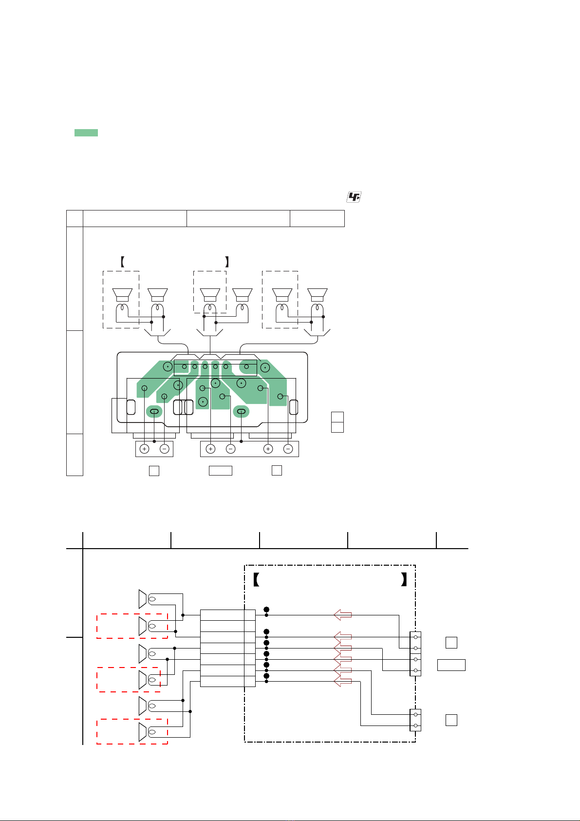
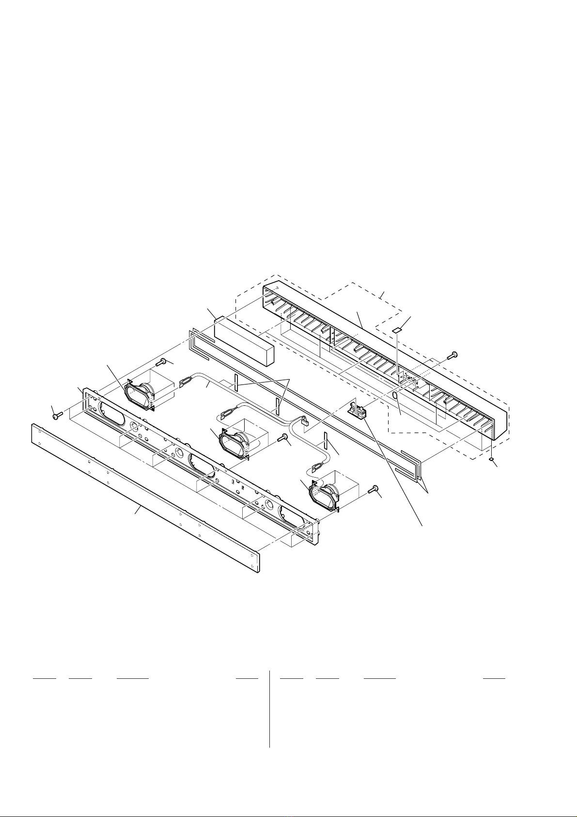
SS-SPEAKER BOARD
*****************
< CONNECTOR >
CN892 1-691-768-11 PLUG (MICRO CONNECTOR) 6P
< TERMINAL >
TB891 1-780-816-11 TERMINAL BOARD (SPEAKER) (R/CENTER)
TB892 1-780-815-11 TERMINAL BOARD (SPEAKER) (L)
*************************************************************
MISCELLANEOUS (SS-CT150)
**************
5 1-837-277-11 CORD WITH CONNECTOR
SP891 1-858-312-11 LOUDSPEAKER (5X9 cm) (FRONT R-ch)
SP893 1-858-312-11 LOUDSPEAKER (5X9 cm) (CENTER)
SP895 1-858-312-11 LOUDSPEAKER (5X9 cm) (FRONT L-ch)
*************************************************************
MISCELLANEOUS (SS-CT350)
**************
60 1-837-277-21 CORD WITH CONNECTOR
SP891 1-858-376-11 LOUDSPEAKER (4X7 cm) (FRONT R-ch)
SP892 1-858-376-11 LOUDSPEAKER (4X7 cm) (FRONT R-ch)
SP893 1-858-377-11 LOUDSPEAKER (4 cm) (CENTER)
SP894 1-858-377-11 LOUDSPEAKER (4 cm) (CENTER)
SP895 1-858-376-11 LOUDSPEAKER (4X7 cm) (FRONT L-ch)
SP896 1-858-376-11 LOUDSPEAKER (4X7 cm) (FRONT L-ch)
Ref. No. Part No. Description Remark
SS-SPEAKER
When indicating parts by reference num-
ber, please include the board name.
Note:
• Due to standardization, replacements in
the parts list may be different from the
parts specified in the diagrams or the com-
ponents used on the set.
• -XX and -X mean standardized parts, so
they may have some difference from the
original one.
• Items marked “*” are not stocked since
they are seldom required for routine ser-
vice. Some delay should be anticipated
when ordering these items.
• RESISTORS
All resistors are in ohms.
METAL: Metal-film resistor.
METAL OXIDE: Metal oxide-film resistor.
F: nonflammable
• CAPACITORS
uF: μF
• COILS
uH: μH
• SEMICONDUCTORS
In each case, u: μ, for example:
uA. . : μA. . , uPA. . , μPA. . ,
uPB. . : μPB. . , uPC. . , μPC. . ,
uPD. . : μPD. .

MEMO
SS-CT150/CT350
9

SS-CT150/CT350
REVISION HISTORY
Checking the version allows you to jump to the revised page.
Also, clicking the version at the top of the revised page allows you to jump to the next revised page.
Ver. Date Description of Revision
1.0 2010.03 New
This manual suits for next models
1
Table of contents
Other Sony Speakers System manuals

Sony
Sony SA-VE155 User manual

Sony
Sony HT-CT390 User manual

Sony
Sony SS-LAC305ED Installation instructions manual

Sony
Sony SS-CR300 User manual

Sony
Sony HT-ST3 User manual

Sony
Sony SS-TL20 User manual

Sony
Sony SS-RS155 User manual

Sony
Sony SA-S1 User manual

Sony
Sony SS-CN700ED User manual

Sony
Sony SS-DP1000DW User manual

Sony
Sony SRS-Z510C User manual

Sony
Sony SRS-Z750 User manual

Sony
Sony SS-TSB101 User manual

Sony
Sony SRS-Z500 User manual

Sony
Sony SRS-T57 User manual

Sony
Sony HT-NT5 User manual

Sony
Sony HT-A3000 User guide

Sony
Sony SS-CN295 User manual

Sony
Sony SS-DP1000DW User manual

Sony
Sony SRS-D4100 Operating Instructions (primary... User manual