4
If it still persists...
Check that there is no other source of
magnetism* near the TV set. Any other source
of magnetism can cause color irregularity due
to an interaction with the speaker.
* Examples of sources of magnetism: Rack,
magnets attached to secure the doors of the
TV stand, health tools, magnets used with
a toy, etc.
On installation
• Do not install the speaker near heat sources
such as radiators or air ducts, or in a place
subject to direct sunlight, excessive dust,
mechanical vibration or shock.
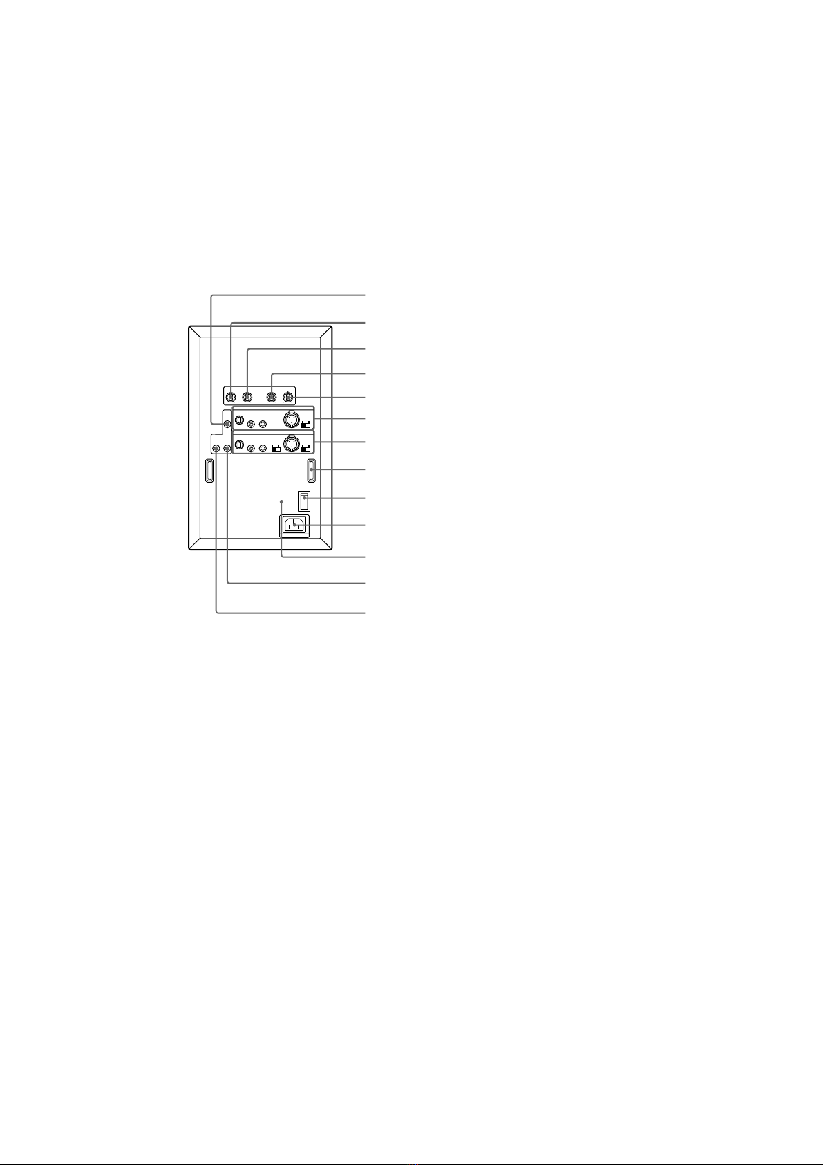
• Good ventilation is essential to prevent
internal heat buildup in the speaker. Place
the speaker in a location with adequate air
circulation. Do not place the speaker on a
soft surface or too close to a wall as this
may obstruct the ventilation hole on the
back.
On cleaning the cabinet
Clean the cabinet with a soft cloth lightly
moistened with water. Do not use any type
of abrasive pad, scouring powder or solvent
such as alcohol or benzine.
If you have any questions or problems
concerning your speaker that is not covered
in this manual, please consult your nearest
Sony dealer.
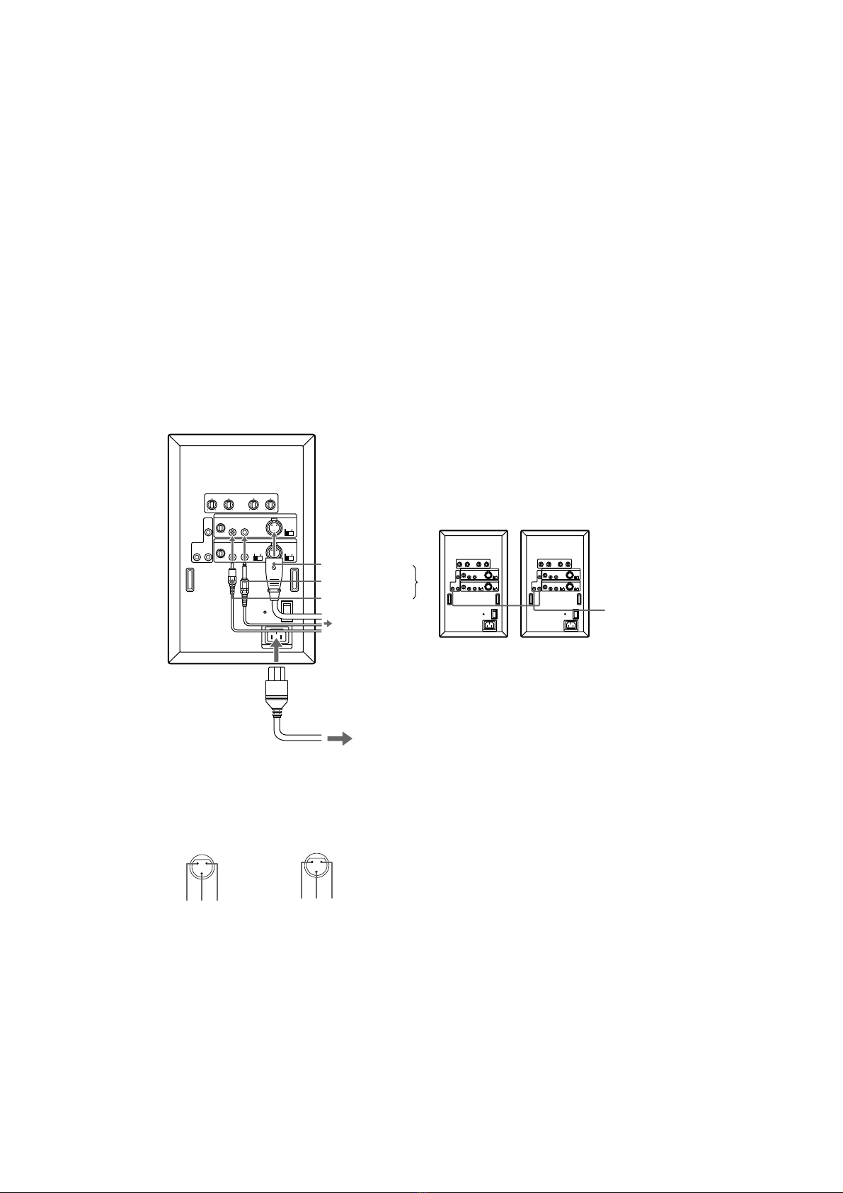
Precautions
• Remove the protective cover after you have
connected the speaker and placed it in its
final position.
• When listening at large volumes, we
recommend keeping the sound at a level
where it does not distort.
• To prevent damage to the speaker unit, be
sure to attatch the supplied protective
cover when moving the speaker or placing
it in storage.
on safety
• Do not attempt to open the enclosure or
modify the speaker unit.
• Before operating the speaker, be sure that
the operating voltage of your speaker is
identical with that of your local power
supply.
• Unplug the speaker from the wall outlet if
it is not to be used for an extended period
of time. To disconnect the cord, pull the
cord by grasping the plug. Never pull the
cord itself.
• Should any liquid or solid object fall into
the speaker, unplug the speaker and have
the speaker checked by qualified personnel
before operating it any further.
• AC power cord must be changed only at
the qualified service shop.
When turning on or off other
equipment
Lower the volume of the speaker to
minimum.
In case color irregularity is
observed on the nearby TV screen
With the magnetically shielded type of the
speaker system, the speakers can be installed
near a TV set. However, color irregularity
may still be observed on the TV screen
depending on the type of your TV set.
If color irregularity is observed...
Turn off the TV set once, then turn it on after
15 to 30 minutes.
If color irregularity is observed again...
Place the speakers further apart from the TV
set.