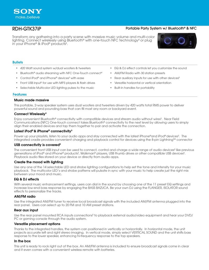
Sony SS-SHAKE10 User manual

SSSHAKEX70SS-SHAKE30/SSSHAKEX30SS-SHAKE10/SSSHAKEX10
SERVICE MANUAL
Sony Corporation
Published by Sony EMCS (Malaysia) PG Tec
SS-SHAKE10/SHAKE30/
SSSHAKEX10/SSSHAKEX30/SSSHAKEX70
SSSHAKEX10P/SSSHAKEX30P/SSSHAKEX70P
SPEAKER SYSTEM
• SS-SHAKE10 is front speakers in SHAKE-X10.
• SS-SHAKE30 is front speakers in SHAKE-X30.
• SSSHAKEX10 is front speakers in SHAKE-X10D.
• SSSHAKEX30 is front speakers in SHAKE-X30D.
• SSSHAKEX70 is front speakers in SHAKE-X70D.
• SSSHAKEX10P is the package speaker of front speakers in SHAKE-X10D.
• SSSHAKEX30P is the package speaker of front speakers in SHAKE-X30D.
• SSSHAKEX70P is the package speaker of front speakers in SHAKE-X70D.
Ver. 1.3 2019.10
9-890-689-04
2019J80-1
© 2019.10
SPECIFICATIONS
Speaker System
SSSHAKEX70
Speaker system:
3-way, Sound Pressure Horn
Speaker unit:
Woofers: 150 mm, cone type
Tweeters: 25 mm, horn type
Subwoofers: 380 mm, cone type
Rated impedance:
8 ohms
Dimensions (w/h/d) (Approx.):
510 mm × 773 mm × 491 mm
Mass (Approx.):
30.6 kg
SS-SHAKE30/SSSHAKEX30
Speaker system:
2-way, Sound Pressure Horn
Speaker unit:
Tweeters: 25 mm (1 in), horn type
Subwoofers: 250 mm (9 7/8 in), cone type
Rated impedance:
4 ohms
Dimensions (w/h/d) (Approx.):
368 mm × 585 mm × 391 mm
(14 1/2 in × 23 1/8 in × 15 1/2 in)
Mass (Approx.):
16.1 kg (35 lb 8 oz)
SS-SHAKE10/SSSHAKEX10
Speaker system:
2-way, Sound Pressure Horn
Speaker unit:
Tweeters: 25 mm (1 in), horn type
Subwoofers: 200 mm (7 7/8 in), cone type
Rated impedance:
4 ohms
Dimensions (w/h/d) (Approx.):
315 mm × 490 mm × 388 mm
(12 1/2 in × 19 3/8 in × 15 3/8 in)
Mass (Approx.):
12 kg (26 lb 8 oz)
Design and specifi cations are subject to change without notice.
• JIG
When disassembling the set, use the following jig (for front panel
removal).
Part No.: J-2501-238-A JIG FOR SPEAKER REMOVAL
US Model
Canadian Model
SS-SHAKE10/SHAKE30
AEP Model
Thai Model
SSSHAKEX30/SSSHAKEX70
UK Model
SSSHAKEX30
Russian Model
Australian Model
SSSHAKEX10/SSSHAKEX30
E Model
SSSHAKEX10/SSSHAKEX30/
SSSHAKEX70
SYSSET
2019/10/3100:01:58(GMT+09:00)

2
SS-SHAKE10/SHAKE30/SSSHAKEX10/SSSHAKEX30/SSSHAKEX70
SECTION 1
DIAGRAMS
For Schematic Diagrams.
Note:
• C: panel designation.
•Signal path
F: AUDIO
THIS NOTE IS COMMON FOR PRINTED WIRING BOARDS AND SCHEMATIC DIAGRAMS.
(In addition to this, the necessary note is printed in each block.)
For Printed Wiring Boards.
Note:
• X: Parts extracted from the component side.
• : Pattern from the side which enables seeing.
(The other layers' patterns are not indicated.)
1-1. PRINTED WIRING BOARD – SPK LED Board (SHAKE10/SHAKE30/SSSHAKEX10/SSSHAKEX30) –
• : Uses unleaded solder.
1-2. SCHEMATIC DIAGRAM – SPK LED Board (SHAKE10/SHAKE30/SSSHAKEX10/SSSHAKEX30) –
1
A
B
C
D
2345678
JL2702
JL2701
JR
JR2701
JR
JR2702
JR
JR2703
14
CN2700
D2700
JL2700
JL2703
1-888-253-
21
(21) 1-888-253-
21
(21)
SPK LED BOARD
(SHAKE10/SHAKE30/SSSHAKEX10/
SSSHAKEX30)
(COMPONENT SIDE)
SPK LED BOARD
(SHAKE10/SHAKE30/SSSHAKEX10/
SSSHAKEX30)
(CONDUCTOR SIDE)
GA
RA
BA
GK
RK
BK
GK
BK
RK
GA
BA
RA
D2700
LED
SPEAKER
L/R
1
A
B
C
D
2345678
SPK LED BOARD
SHAKE10/SHAKE30/SSSHAKEX10/SSSHAKEX30
JL2700
JL2703
JL2702
JL2701 1
2
3
4
4P
CN2700
M+5V
RED_LED
BLUE_LED
GREEN_LED
R
G
B
SMLVN6RGB1U17QYB
D2700
LED
SPEAKER
L/R
SYSSET
2019/10/3100:01:58(GMT+09:00)

3
SS-SHAKE10/SHAKE30/SSSHAKEX10/SSSHAKEX30/SSSHAKEX70
1-3. PRINTED WIRING BOARDS – SPK LED, SPK RGB AND SPLITTER Board (SSSHAKEX70) –
• : Uses unleaded solder.
1
A
B
C
D
E
F
G
H
I
J
K
2345678
14
CN1800
14 CN1801
16
CN1802
JL1803
JL1801
JL1800
JL1802
JL1804
JL1806
JL1805
R3001
D3001
14
56
CN3001
CL3001
R3002
R3003
CL3003
CL3002
CL3004
16
78
CN3101
CL3101
CL3102
CL3103
CL3104
CL3105
CL3106
D31001
1-887-624-
31
(31) 1-887-624-
31
(31)
1-894-347-
11
(11) 1-894-347-
11
(11)
1-894-346-
11
(11) 1-894-346-
11
(11)
SPK RGB BOARD
(SSSHAKEX70)
(COMPONENT SIDE)
SPLITTER BOARD
(SSSHAKEX70)
(COMPONENT SIDE)
SPLITTER BOARD
(SSSHAKEX70)
(CONDUCTOR SIDE)
SPK RGB BOARD
(SSSHAKEX70)
(CONDUCTOR SIDE)
SPK LED BOARD
(SSSHAKEX70)
(COMPONENT SIDE)
SPK LED BOARD
(SSSHAKEX70)
(CONDUCTOR SIDE)
GA
RA
BA
GK
RK
BK
GK
BK
RK
GA
BA
RA
D31001
GA
RA
BA
GK
RK
BK
GK
BK
RK
GA
BA
RA
D3001
LED
SPEAKER
L/R
SYSSET
2019/10/3100:01:58(GMT+09:00)

4
SS-SHAKE10/SHAKE30/SSSHAKEX10/SSSHAKEX30/SSSHAKEX70
1-4. SCHEMATIC DIAGRAM – SPK LED, SPK RGB AND SPLITTER Board (SSSHAKEX70) –
1
A
B
C
D
E
F
G
H
I
J
K
2345678
SPK LED BOARD
SPK RGB BOARD
SSSHAKEX70
SSSHAKEX70
SSSHAKEX70
SPLITTER BOARD
CL3004
CL3001
CL3002
4P
CN3001
1LED+5.2V
2RED
3BLUE
4GREEN
BLU
RED
GRN
SMLVN6RGB1U18QYA
D3001
CL3003
68R3001
68R3002
68R3003
LED
SPEAKER
L/R
6P
CN3101
1GREEN_K
2BLUE_K
3RED_K
4RED_A
5BLUE_A
6GREEN_A
CL3104
CL3105
CL3106
CL3102
CL3101
CL3103
BLU
RED
GRN N
SMLVN6RGB1U18QYA
D31001
1
2
3
4
5
6
6P
CN1802
GREEN
BLUE
RED
RED_LED
BLUE_LED
GREEN_LED
1
2
3
4
4P
CN1800
RGB +13V
RED
BLUE
GREEN
1
2
3
4
4P
CN1801
RGB +13V
RED_LED
BLUE_LED
GREEN_LED JL1800
JL1801
JL1802
JL1803
JL1804
JL1806
JL1805
SYSSET
2019/10/3100:01:58(GMT+09:00)

Ver. 1.3
5
SS-SHAKE10/SHAKE30/SSSHAKEX10/SSSHAKEX30/SSSHAKEX70
1-5. PRINTED WIRING BOARD – SPK PARTY GB Board
(SHAKE10/SHAKE30/SSSHAKEX10/SSSHAKEX30) –
• : Uses unleaded solder.
1
A
B
C
D
E
F
G
H
I
J
K
2345678
R3901
R3902
CL3904
CL3905
CL3906
14
56
CN3900
CL3805
CL3806
CL3803
CL3804
D3902 D3901
1-981-986-
12
(12)
1-981-986-
12
(12)
SPK PARTY GB BOARD
(SHAKE10/SHAKE30/SSSHAKEX10/SSSHAKEX30)
(COMPONENT SIDE)
SPK PARTY GB BOARD
(SHAKE10/SHAKE30/SSSHAKEX10/SSSHAKEX30)
(CONDUCTOR SIDE)
GA
RA
BA
GK
RK
BK
GK
BK
RK
GA
BA
RA
D3901, D3902
LED
SPEAKER
L/R
SYSSET
2019/10/3100:01:58(GMT+09:00)

Ver. 1.3
6
SS-SHAKE10/SHAKE30/SSSHAKEX10/SSSHAKEX30/SSSHAKEX70
1-6. PRINTED WIRING BOARD – SPK PARTY LED Board (SSSHAKEX70) – • : Uses unleaded solder.
1
A
B
C
D
E
F
G
H
I
J
K
2345678
D3800
D3801
D3802
CL3904
CL3905
CL3906
CL3805 CL3806
CL3803
CL3804
R3800
R3802
14
5
6
R3801
CN3800
1-981-986-
12
(12)
1-981-986-
12
(12)
SPK PARTY LED BOARD
(SSSHAKEX70)
(COMPONENT SIDE)
SPK PARTY LED BOARD
(SSSHAKEX70)
(CONDUCTOR SIDE)
GA
RA
BA
GK
RK
BK
GK
BK
RK
GA
BA
RA
D3800, D3801, D3802
LED
SPEAKER
L/R
SYSSET
2019/10/3100:01:58(GMT+09:00)

Ver. 1.3
7
SS-SHAKE10/SHAKE30/SSSHAKEX10/SSSHAKEX30/SSSHAKEX70
SECTION 2
EXPLODED VIEWS
The components identifi ed by mark 9 con-
tain confi dential information.
Strictly follow the instructions whenever the
components are repaired and/or replaced.
Les composants identifi és par la marque
9 contiennent des informations confi den-
tielles.
Suivre scrupuleusement les instructions
chaque fois qu’un composant est rem-
placé et / ou réparé.
2-1. SS-SHAKE10/SSSHAKEX10
1 4-874-614-12 SCREW (1) (3.5X14), TAPPING
2 4-558-070-01 CORNER PROTECTOR
3 4-176-619-01 FOOT, RUBBER
4 4-874-614-02 SCREW (1) (3.5X14), TAPPING
5 1-826-143-91 LOUDSPEAKER (2.5CM)
6 A-2184-904-A PANEL ASSY, FRONT
7 4-238-407-12 SCREW (1) (4X20), +BV TAPPING
8 1-002-856-11 LOUDSPEAKER (20CM)
9 4-558-820-01 + FLAT TAPPING SCREW - ED BK
10 A-2183-270-A SPK PARTY GB BOARD, COMPLETE
11 4-690-847-02 BRACKET, PARTY L
11 4-690-849-02 BRACKET, PARTY R
12 4-690-850-01 LENS, PARTY
13 4-690-851-02 COVER, PARTY L
13 4-690-852-02 COVER, PARTY R
#1 7-685-646-79 SCREW +BVTP 3X8 TYPE2 IT-3
#2 7-685-647-79 SCREW +BVTP 3X10 TYPE2 N-S
ns not supplied
Ref. No. Part No. Description Remark Ref. No. Part No. Description Remark
The components identified by mark 0
or dotted line with mark 0 are critical for
safety.
Replace only with part number specifi ed.
Les composants identifi és par une marque
0 sont critiques pour la sécurité.
Ne les remplacer que par une pièce por-
tant le numéro spécifi é.
Note:
• -XX and -X mean standardized parts, so
they may have some diff erence from the
original one.
• Items marked “*” are not stocked since they
are seldom required for routine service.
Some delay should be anticipated when
ordering these items.
• Abbreviation
AR : Argentina model
AUS : Australian model
CND : Canadian model
E4 : African model
E12 : 220 – 240 V AC area in E model
EA : Saudi Arabia model
LA9 : Latin-American model
MY : Malaysia model
RU : Russian model
TH : Thai model
ns
ns
ns
ns
SPK LED board
(ns)
#1
#2
#1
ns
#1
1
1
2
2
2
9
9
11 12
13
10
2
3
3
6
7
8
4
5
3
3
Note 1: This diagram is for R channel speaker.
The mechanical position of L channel is reversed.
Note 2:
LOUDSPEAKER (20CM) for this set has been changed in
the midway of production. LOUDSPEAKER (20CM) for L
channel and R channel in this set is synchronized. When
any of the loudspeaker replacement is needed, check the
part number and order the same part for both channels.
SYSSET
2019/10/3100:01:58(GMT+09:00)

Ver. 1.3
8
SS-SHAKE10/SHAKE30/SSSHAKEX10/SSSHAKEX30/SSSHAKEX70
51
51
#1
52
52
52
52
53
53
54
54
54
55
56
57 58
57
53
53
59
61 62
63
60
59
#1
#1
ns
ns
ns
ns
ns
SPK LED board
(ns)
2-2. SS-SHAKE30/SSSHAKEX30
51 4-874-614-12 SCREW (1) (3.5X14), TAPPING
52 4-558-070-01 CORNER PROTECTOR
53 4-176-619-01 FOOT, RUBBER
54 4-874-614-02 SCREW (1) (3.5X14), TAPPING
55 1-826-143-73 LOUDSPEAKER (2.5CM)
56 A-2184-903-A PANEL FRONT ASSY
57 4-238-407-12 SCREW (1) (4X20), +BV TAPPING
58 1-859-225-11 LOUDSPEAKER (25CM)
59 4-558-820-01 + FLAT TAPPING SCREW - ED BK
60 A-2183-270-A SPK PARTY GB BOARD, COMPLETE
61 4-690-847-02 BRACKET, PARTY L
61 4-690-849-02 BRACKET, PARTY R
62 4-690-850-01 LENS, PARTY
63 4-690-851-02 COVER, PARTY L
63 4-690-852-02 COVER, PARTY R
#1 7-685-646-79 SCREW +BVTP 3X8 TYPE2 IT-3
ns not supplied
Ref. No. Part No. Description Remark Ref. No. Part No. Description Remark
Note: This diagram is for R channel speaker.
The mechanical position of L channel is reversed.
SYSSET
2019/10/3100:01:58(GMT+09:00)

Ver. 1.3
9
SS-SHAKE10/SHAKE30/SSSHAKEX10/SSSHAKEX30/SSSHAKEX70
B
B
A
A
C
C
ns
ns
ns
ns
ns
ns
SPLITTER board
(ns)
SPK LED board
(ns)
SPK RGB board
(ns)
ns
ns
ns
101
112
112
116
117
118
119
112
112
106
107
110 111
102
102
102
112
112
113
113
113
103
104
110
105
113
115
115
114
114
114
114
112
112
101
101
102
#1
#1
ns
ns
ns ns
ns
ns
ns ns
– L channel speaker rear view – – R channel speaker rear view –
102
102
102
108 108
109 109
102
101 4-558-820-01 + FLAT TAPPING SCREW - ED BK
102 4-874-614-02 SCREW (1) (3.5X14), TAPPING
103 1-848-766-21 CABLE WITH CONNECTOR
104 1-848-766-11 CABLE WITH CONNECTOR
105 A-2184-902-A PANEL (SW) ASSY, FRONT
106 4-238-407-02 SCREW (1) (4X20), +BV TAPPING
107 1-002-854-11 LOUDSPEAKER (15CM)
108 1-826-143-73 LOUDSPEAKER (2.5CM)
109 A-2064-677-A PANEL (L) ASSY, FRONT
109 A-2064-678-A PANEL (R) ASSY, FRONT
110 4-569-090-21 SCR TPBV +4 (SW/W10) (HR) - 3B ZN
111 1-002-853-11 LOUDSPEAKER (38CM)
112 4-532-593-02 SCREW (4X13) (TR-184A)
113 4-548-810-01 PROTECTOR CORNER, FRONT
114 4-548-811-01 PROTECTOR CORNER, REAR
115 4-558-819-01 FOOT
116 A-2167-943-A SPK PARTY LED BOARD, COMPLETE
117 4-690-847-02 BRACKET, PARTY L
117 4-690-849-02 BRACKET, PARTY R
118 4-690-850-01 LENS, PARTY
119 4-690-851-02 COVER, PARTY L
119 4-690-852-02 COVER, PARTY R
#1 7-685-646-79 SCREW +BVTP 3X8 TYPE2 IT-3
ns not supplied
Ref. No. Part No. Description Remark Ref. No. Part No. Description Remark
2-3. SSSHAKEX70
Note 1: This diagram is for R channel speaker.
The mechanical position of L channel is reversed.
Note 2:
LOUDSPEAKER (15CM) for this set has been changed in
the midway of production. LOUDSPEAKER (15CM) for L
channel and R channel in this set is synchronized. When
any of the loudspeaker replacement is needed, check the
part number and order the same part for both channels.
Note 3:
LOUDSPEAKER (38CM) for this set has been changed in
the midway of production. LOUDSPEAKER (38CM) for L
channel and R channel in this set is synchronized. When
any of the loudspeaker replacement is needed, check the
part number and order the same part for both channels.
SYSSET
2019/10/3100:01:58(GMT+09:00)

SPK LED BOARD
*************
< CONNECTOR >
CN2700 1-580-057-11 PIN, CONNECTOR (SMD) 4P
(SHAKE10/SHAKE30/SSSHAKEX10/SSSHAKEX30)
CN3001 1-580-057-11 PIN, CONNECTOR (SMD) 4P (SSSHAKEX70)
< DIODE >
D2700 6-503-944-51 DI SMLVN6RGB1U17QYB
(SHAKE10/SHAKE30/SSSHAKEX10/SSSHAKEX30)
D3001 6-503-944-61 DI SMLVN6RGB1U18QYA (SSSHAKEX70)
< JUMPER RESISTOR >
JR2701 1-216-864-91 SHORT CHIP 0
(SHAKE10/SHAKE30/SSSHAKEX10/SSSHAKEX30)
JR2702 1-216-864-91 SHORT CHIP 0
(SHAKE10/SHAKE30/SSSHAKEX10/SSSHAKEX30)
JR2703 1-216-805-11 METAL CHIP 47 5% 1/10W
(SHAKE10/SHAKE30/SSSHAKEX10/SSSHAKEX30)
************************************************************
A-2183-270-A SPK PARTY GB BOARD, COMPLETE
(SHAKE10/SHAKE30/SSSHAKEX10/SSSHAKEX30)
****************************
************************************************************
A-2167-943-A SPK PARTY LED BOARD, COMPLETE
(SSSHAKEX70)
*****************************
************************************************************
SPK RGB BOARD (SSSHAKEX70)
**************
< CONNECTOR >
CN3101 1-580-789-21 PIN, CONNECTOR (SMD) 6P
< DIODE >
D31001 6-503-944-61 DI SMLVN6RGB1U18QYA
************************************************************
SPLITTER BOARD (SSSHAKEX70)
**************
< CONNECTOR >
CN1800 1-564-720-11 PIN, CONNECTOR (SMALL TYPE) 4P
CN1801 1-564-720-11 PIN, CONNECTOR (SMALL TYPE) 4P
CN1802 1-564-722-11 PIN, CONNECTOR (SMALL TYPE) 6P
Ver. 1.1
10
SS-SHAKE10/SHAKE30/SSSHAKEX10/SSSHAKEX30/SSSHAKEX70
SECTION 3
ELECTRICAL PARTS LIST
SPK LED
SPK PARTY LED
SPK PARTY GB
SPK RGB
SPLITTER
Ref. No. Part No. Description Remark Ref. No. Part No. Description Remark
When indicating parts by reference num-
ber, please include the board name.
Note:
• Due to standardization, replacements in
the parts list may be different from the
parts specified in the diagrams or the
components used on the set.
• -XX and -X mean standardized parts, so
they may have some difference from the
original one.
• RESISTORS
All resistors are in ohms.
METAL: Metal-fi lm resistor.
METAL OXIDE: Metal oxide-fi lm resistor.
F: nonfl ammable
• Items marked “*” are not stocked since
they are seldom required for routine ser-
vice.
Some delay should be anticipated when
ordering these items.
• SEMICONDUCTORS
In each case, u: μ, for example:
uA. . : μA. . , uPA. . , μPA. . ,
uPB. . : μPB. . , uPC. . , μPC. . ,
uPD. . : μPD. .
• CAPACITORS
uF: μF
• COILS
uH: μH
• Abbreviation
AR : Argentina model
AUS : Australian model
CND : Canadian model
E4 : African model
E12 : 220 – 240 V AC area in E model
EA : Saudi Arabia model
LA9 : Latin-American model
MY : Malaysia model
RU : Russian model
TH : Thai model
The components identified by mark 0
or dotted line with mark 0 are critical for
safety.
Replace only with part number specifi ed.
Les composants identifi és par une marque
0 sont critiques pour la sécurité.
Ne les remplacer que par une pièce por-
tant le numéro spécifi é.
The components identifi ed by mark 9 con-
tain confi dential information.
Strictly follow the instructions whenever the
components are repaired and/or replaced.
Les composants identifi és par la marque
9 contiennent des informations confi den-
tielles.
Suivre scrupuleusement les instructions
chaque fois qu’un composant est rem-
placé et / ou réparé.
SYSSET
2019/10/3100:01:58(GMT+09:00)
MEMO
11
SS-SHAKE10/SHAKE30/SSSHAKEX10/SSSHAKEX30/SSSHAKEX70
SYSSET
2019/10/3100:01:58(GMT+09:00)

SS-SHAKE10/SHAKE30/SSSHAKEX10/SSSHAKEX30/SSSHAKEX70
REVISION HISTORY
Ver. Date Description of Revision
1.0 2017.03 New
1.1 2017.06 Addition of Malaysia and Russian models (SSSHAKEX10).
Addition of 220-240 V AC area in E model, Malaysia, Russian and Thai models (SSSHAKEX30).
Addition of Malaysia and Thai models (SSSHAKEX70).
Change description of Ref. No. #1 in page 7, 8 and 9.
1.2 2018.09 Add Ref. No. 12 and 13 in page 7 (Service code changed).
Add Ref. No. 62 and 63 in page 8 (Service code changed).
Add Ref. No. 118 and 119 in page 9 (Service code changed).
1.3 2019.10 Add note for LOUDSPEAKER (15CM) and LOUDSPEAKER (38CM) in page 9.
Add note for LOUDSPEAKER (20CM) in page 7.
Change description of Ref. No. #1 in page 7, 8 and 9.
Change of SPK PARTY GB board and SPK PARTY LED board (suffi x 12).
Change P/N and description of Ref. No. 8 in page 7.
Change P/N and description of Ref. No. 107 and 111 in page 9.
How to search for a contact point of signal lines or the like in DIAGRAMS SECTION
If a contact point of a BLOCK DIAGRAM, PRINTED WIRING BOARD or SCHEMATIC DIAGRAM is shown in a diff erent page, use
the PDF fi le search function to fi nd one.
e.g.) If a contact point is shown as , follow the procedure below.
Procedure:
1. Press the [F] key while pressing the [Ctrl] key.
2. Input “>001Z” in the search box and press the [Enter] key.
3. The relevant part (page), where the contact point is shown, appears.
Note: If you still see the original page, press the [Enter] key again.
SYSSET
2019/10/3100:01:58(GMT+09:00)
This manual suits for next models
7
Table of contents
Other Sony Speakers manuals

Sony
Sony XS-A82P Product guide

Sony
Sony SRS-D2100 User manual

Sony
Sony SS-MB350H User manual

Sony
Sony XS-K1330 User manual

Sony
Sony HT-CT390 User guide

Sony
Sony XS-W4121 User manual

Sony
Sony LF-S50G User manual

Sony
Sony XSF-1021 Instructions (primary manual) User manual

Sony
Sony WS-IT1000F User manual

Sony
Sony XS-W6921 User manual