SS-NA8ES
2
SECTION 1
SERVICING NOTES
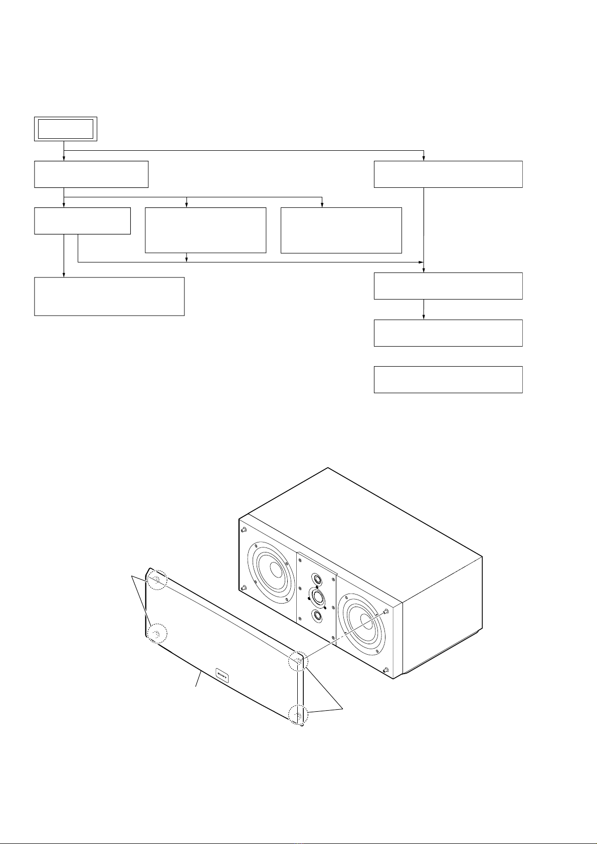
NOTE THE SPEAKER UNITS REPLACING
Refer to “2. DISASSEMBLY” (page 4 or subsequent) for the re-
placement procedure of each loudspeaker unit.
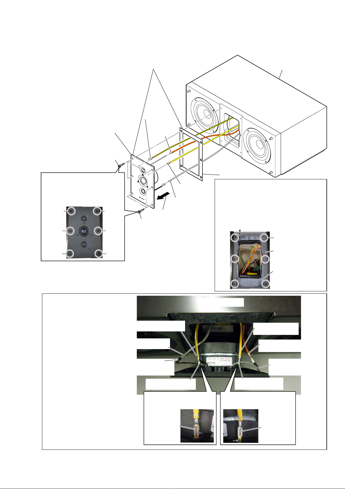
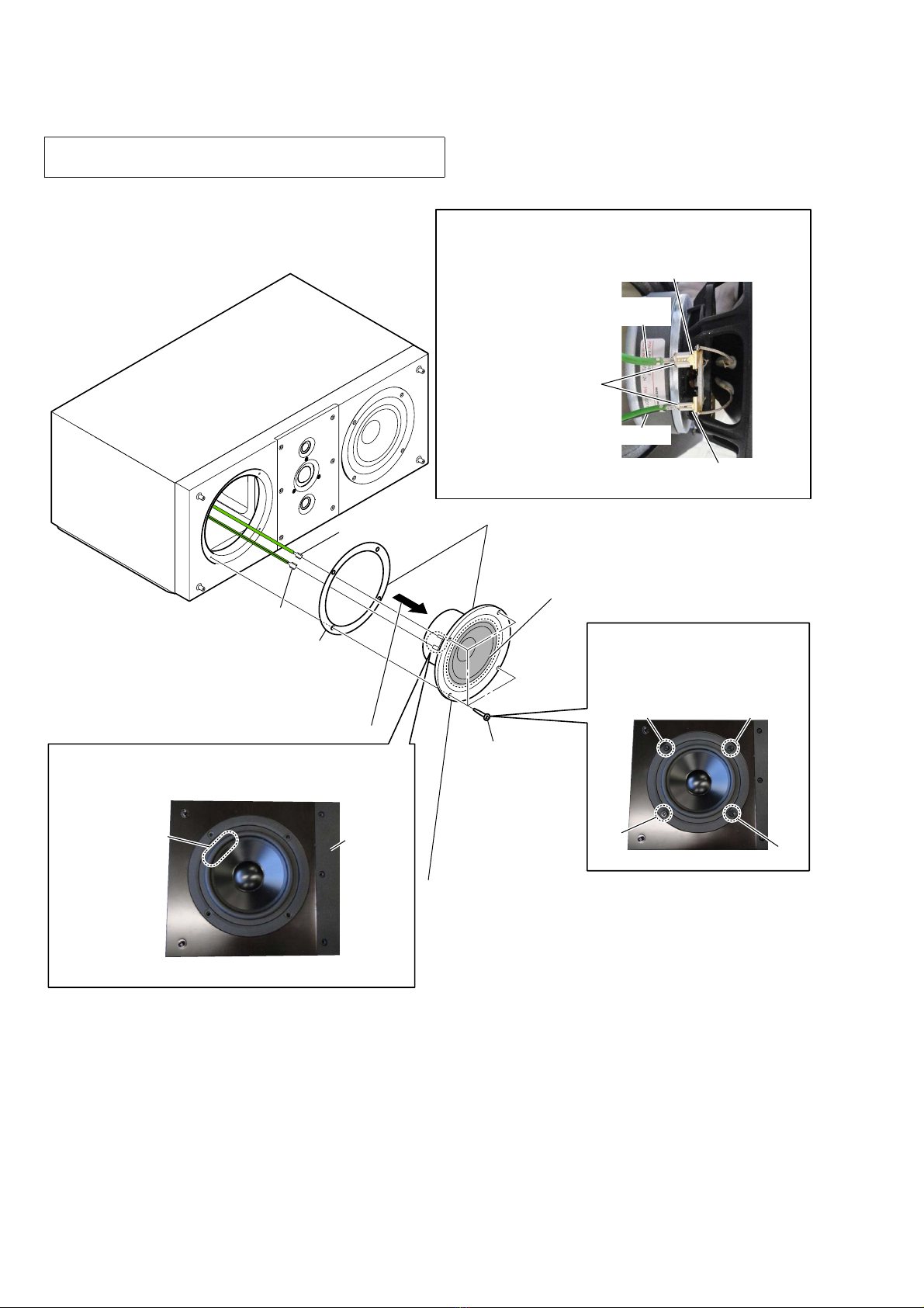
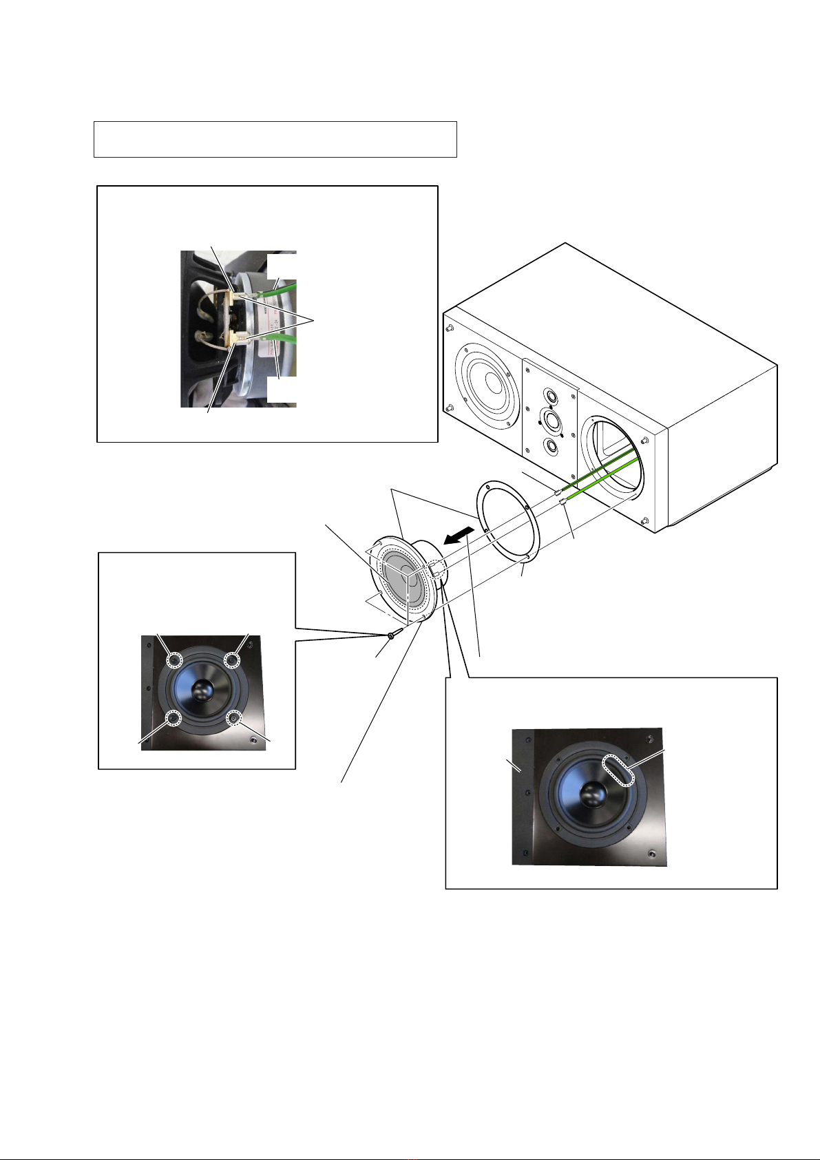
1. Woofer (SP1, SP2)
When exchanging Woofer (13 cm), in order to balance sound
quality on right side and left side, it recommends exchanging
right side and left side simultaneously.
(Example: When exchanging right side Woofer, recommend
also exchanging left side Woofer simultaneously (a total of two
pieces, right side and left side, are exchanged simultaneously))
Please be sure to confirm a customer’s intention in advance.
When a customer’s consent is obtained, please exchange si-
multaneously Woofer of right side and left side (a total of two
pieces).
When a customer’s consent is not obtained, please exchange
only broken Woofer (one piece).
Woofer
Woofer
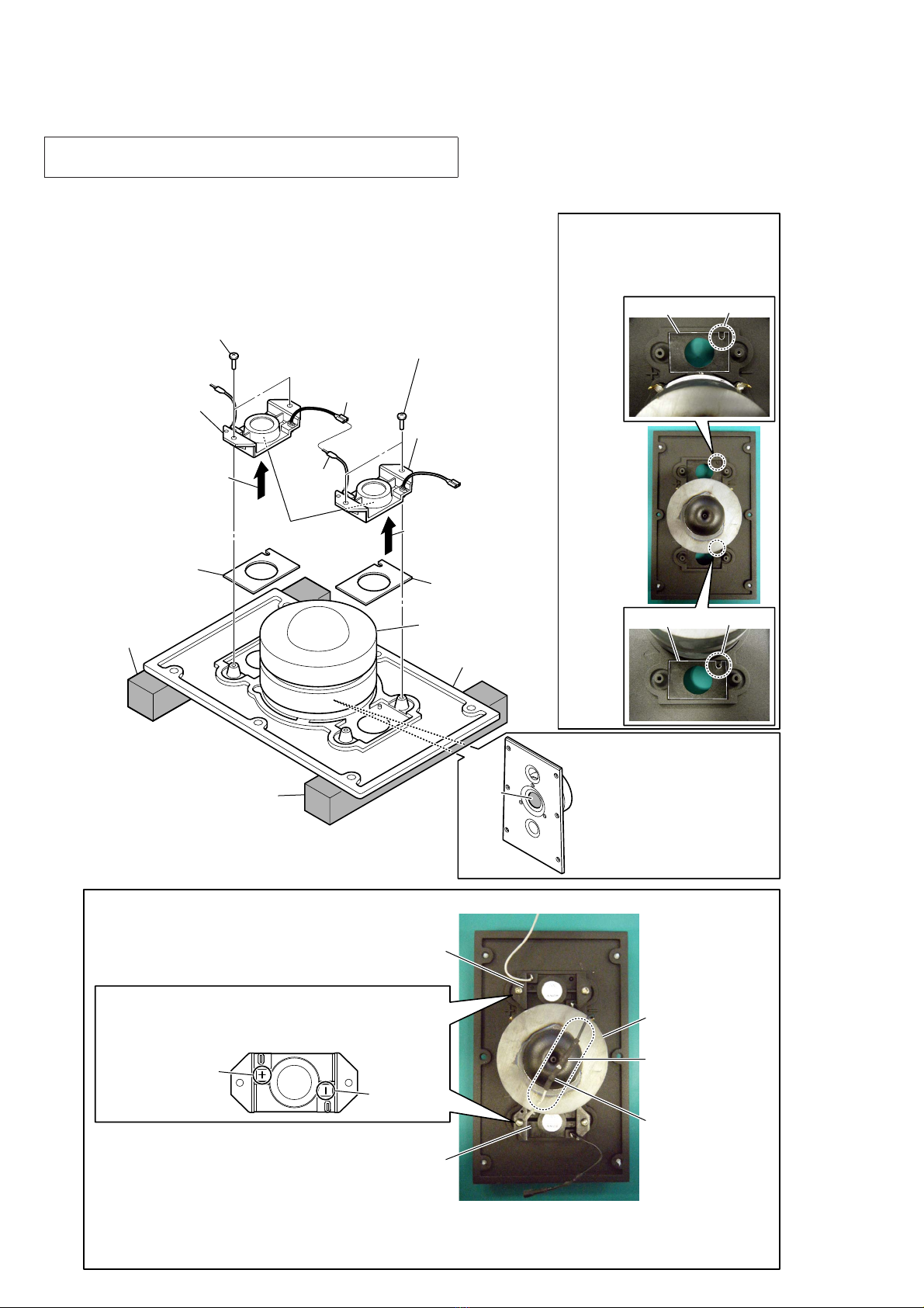
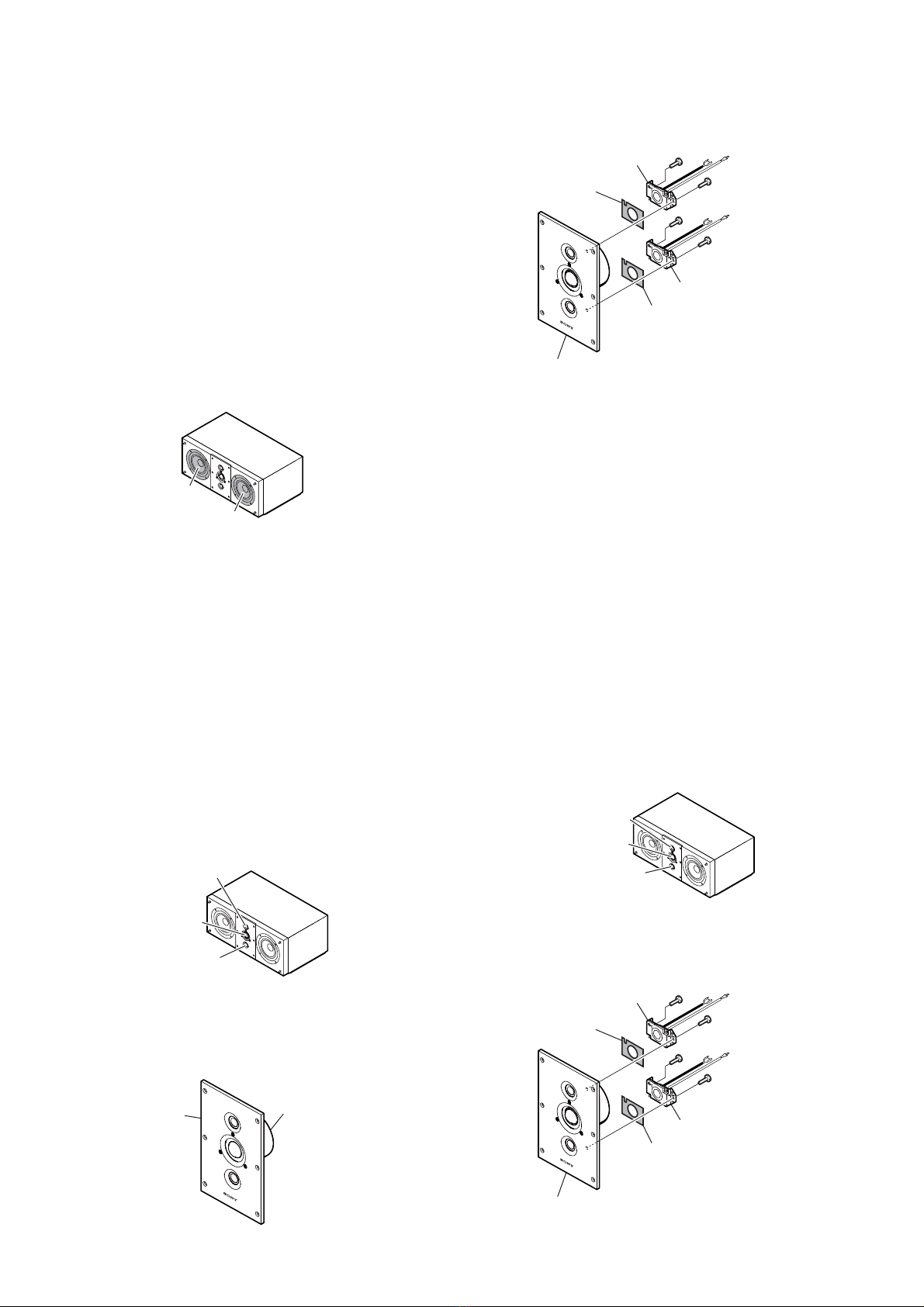
2. Main tweeter (SP5)
1When exchanging Main tweeter (2.5 cm), in order to balance
sound quality on right side and left side, Main tweeter and As-
sist tweeter recommends exchanging right side and left side
simultaneously.
(Example: When exchanging right side Main tweeter (one
piece), recommends also exchanging simultaneously right
side Assist tweeter (two pieces, upper side and lower side),
left side Main tweeter (one piece) and left side Assist tweeter
(two pieces, upper side and lower side) (a total of six pieces,
upper side, lower side, right side and left side, are exchanged
simultaneously))
Please be sure to confirm a customer’s intention in advance.
When a customer’s consent is obtained, please exchange si-
multaneously Main tweeter and Assist tweeter of upper side,
lower side, right side and left side (a total of six pieces).
When a customer’s consent is not obtained, please exchange
only broken Main tweeter (one piece).
Assist tweeter
Assist tweeter
Main tweeter
2Main tweeter (2.5 cm) is exchanged in the form attached to
FACE PLATE.
When exchanging tweeter, please exchange for SPEAKER
(2.5 cm) ASSY including FACE PLATE.
FACE PLATE Main tweeter
SPEAKER (2.5 cm) ASSY
3PACKING (C) is not reused. When Assist tweeter is removed,
please be sure to exchange PACKING (C).
Assist tweeter
Assist tweeter
PACKING (C)
not reused
PACKING (C)
not reused
SPEAKER (2.5 cm) ASSY
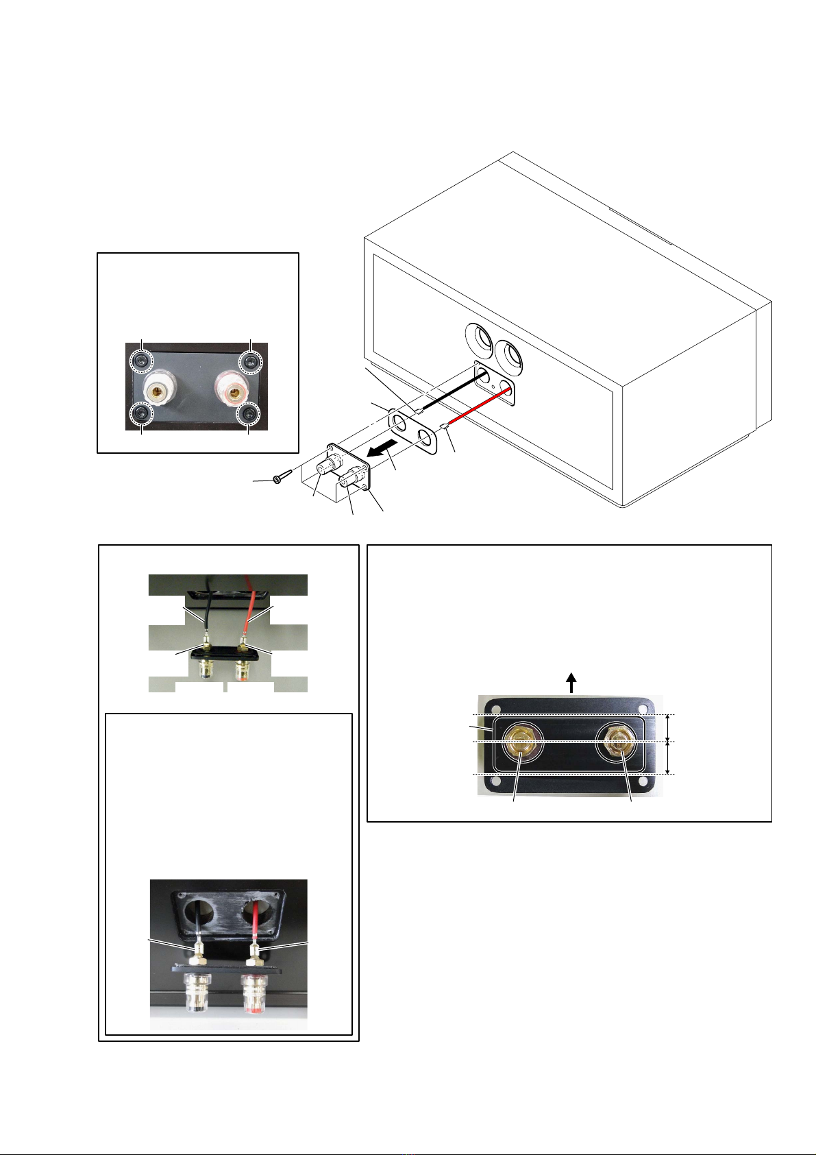
3. Assist tweeter (SP3, SP4)
1When exchanging Assist tweeter (1.9 cm), in order to guar-
antee performance, please be sure to exchange upper side and
lower side simultaneously.
Moreover, in order to balance sound quality on right side and
left side, Assist tweeter and Main tweeter recommends ex-
changing right side and left side simultaneously.
(Example: When exchanging right side Assist tweeter (two
piece, upper side and lower side), recommends also exchang-
ing simultaneously right side Main tweeter (one piece), left
side Assist tweeter (two pieces, upper side and lower side) and
left side Main tweeter (one piece) (a total of six pieces, upper
side, lower side, right side and left side, are exchanged simul-
taneously))
Please be sure to confirm a customer’s intention in advance.
When a customer’s consent is obtained, please exchange si-
multaneously Assist tweeter and Main tweeter of upper side,
lower side, right side and left side (a total of six pieces).
When a customer’s consent is not obtained, please exchange
only broken side Assist tweeter (two piece, upper side and
lower side).
Assist tweeter
(Be sure to exchange
upper side and lower
side simultaneously)
Assist tweeter
(Be sure to exchange
upper side and lower
side simultaneously)
Main tweeter
2PACKING (C) is not reused. When Assist tweeter is removed,
please be sure to exchange PACKING (C).
Assist tweeter
Assist tweeter
PACKING (C)
not reused
PACKING (C)
not reused
SPEAKER (2.5 cm) ASSY