AC
outlet
(STR-GX415/STR-GX315)
(except
for
U.K.
model
of
STR-GX315)
One
switched
(100W
Max.)
Dimensions
Approx.
430
x
135
x
300mm
(w/h/d)
(17
x
53/8
x
11
7/8
inches)
including
projecting
parts
and
controls
Weight
თ.
STR-GX415:
Approx.
7.2kg
(151ხ
1402)
STR-GX315:
Approx.
6.2kg
(131ხ
11о2)
STR-GX215:
Approx.
5.9kg
(131
102)
Accessories
supplied
FM
wire
antenna
(1)
AM
loop
antenna
(1)
Remote
Commander
RM-U141
(STR-GX415/STR-GX315
only)(1)
Sony
batteries
SUM-3(NS)(2)
Design
and
specifications
are
subject
to
change
without
notice.
Note
This
appliance
conforms
with
EEC
Directive
87/308/EEC
regarding
interference
suppression.
MODEL
IDENTIFICATION
—
Model
Number
Portion
—
Carved
on
back
panel
AEP1, AEP2,
German,
East
European
model
:
STR-GX215
AEP1, AEP2,
German,
UK,
East
European
model
:
STR-GX315
AEP1, AEP2,
German
model
:
STR-GX415
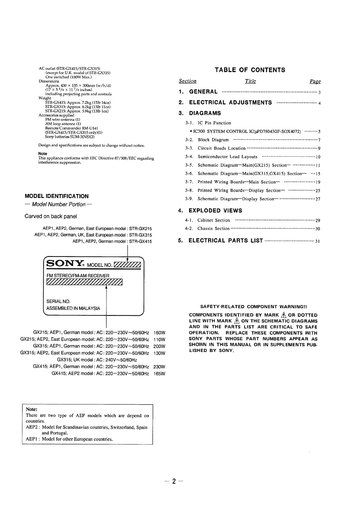
SON
Y.
von
м.
22222222
FM
STEREO/FM-AM
RECEIVER
UANL
SERIAL
NO.
ASSEMBLED
IN
MALAYSIA
GX215;
AEP1,
German
model
:
АС:
220—230V
—50/60Hz
GX215;
AEP2,
East
European
model:
АС:
220—230V—50/60Hz
GX315;
AEP1,
German
model
:
АС:
220—230V
—50/60Hz
GX315;
AEP2,
East
European
model:
АС:
220—230V
—50/60Hz
GX315;
UK
model
:
AC:
240V
—50/60Hz
GX415;
AEP1,
German
model
:
AC
:
220—230V —50/60Hz
GX415;
AEP2
model
:
AC:
220—230V
—50/60Hz
Note:
There
are
two
type
of
AEP
models
countries.
which
are
depend
on
AEP2
:
Model
for
Scandinavian
countries,
Switzerland,
Spain
and
Portugal.
AEP]
:
Model
for
other
European
countries.
160W
110W
200W
130W
230W
165W
TABLE
OF
CONTENTS
Section
Title
Page
1.
GENERAL
--...............................
арыда
3
2.
ELECTRICAL
ADJUSTMENTS
--------------
4
3.
DIAGRAMS
3-1.
IC
Pin
Function
*
1C300
SYSTEM
CONTROL
IC(uPD78043GF-SOX4072)
“еее”
5
3-2.
Block
Diagram
Pree
eee
ee
Sere
Sere
ree
reese
rire
rere
eter
rr
errr
rr
er
rer
7
3-3.
Circuit
Boads
Location
......
Зее
о
я
родня
взора
оо
во
вазу
зв
зо
нь
звене
9
3-4.
Semiconductor
Lead
Layouts
ცელ
10
3-5.
Schematic
Diagram—Main(GX215)
Section
“е...
11
3-6.
Schematic
Diagram—Main(GX315,GX415)
Section—
“15
3-7.
Printed
Wiring
Boards—Main
Section—
ts
19
3-8.
Printed
Wiring
Boards—Display
Section—
+++"...
25
3-9.
Schematic
Diagram
Display
Section—
«mm
27
4.
EXPLODED
VIEWS
4-1
d
Cabinet
Section
СО
&ertsssesossusesussseenesasoasesuséeueeceveeeeee
29
4-2.
Chassis
Section
demnm
nenne
nenne
nnne
nennen
ne
30
5.
ELECTRICAL
PARTS
LIST
·..-.............................
31
SAFETY-RELATED
COMPONENT
WARNING!!
COMPONENTS
!DENTIFIED
BY
MARK
A
OR
DOTTED
LINE
WITH
MARK
A
ON
THE
SCHEMATIC
DIAGRAMS
AND
IN
THE
PARTS
LIST
ARE
CRITICAL
TO
SAFE
OPERATION.
REPLACE
THESE
COMPONENTS
WITH
SONY
PARTS
WHOSE
PART
NUMBERS
APPEAR
AS
SHOWN
IN
THIS
MANUAL
OR
IN
SUPPLEMENTS
PUB-
LISHED
BY
SONY.


