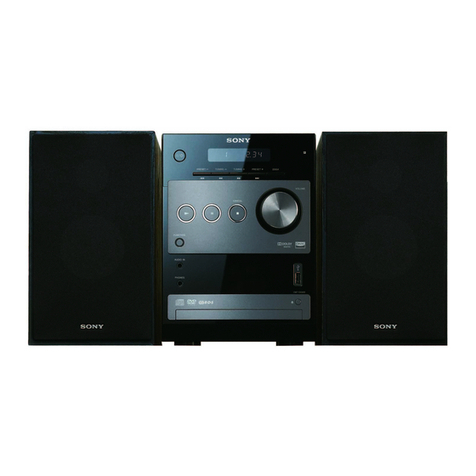
Sony CMT-G1BIP User manual

SERVICEMANUAL
Published by Sony Techno Create Corporation
Sony Corporation
CMT-G1BiP/G1iP
MICROHI-FICOMPONENTSYSTEM
9-893-207-01
2011F05-1
© 2011.06
AEP Model
CMT-G1BiP/G1iP
UK Model
CMT-G1BiP
Chinese Model
CMT-G1iP
Ver. 1.0 2011.06
• CMT-G1BiP/G1iP are composed of following models.
As service manuals are issued for each component model, please
refer to them.
SPECIFICATIONS ACCESSORIES
1-754-102-41 ANTENNA, LOOP (LW.MW) (AM loop antenna)
1-793-184-41 CONNECTOR (F TYPE ADAPTOR)
(FM lead antenna)
1-793-184-41 CONNECTOR (F TYPE ADAPTOR)
(DAB lead antenna) (CMT-G1BiP)
0
1-837-421-61 CORD SET, POWER-SUPPLY (AC power cord)
(UK)
0
1-837-426-61 CORD SET, POWER-SUPPLY (AC power cord)
(AEP)
0
1-838-705-61 CORD SET, POWER-SUPPLY (AC power cord)
(Chinese)
0
1-839-230-11 CONNECTION CORD WITH SPEAKER
(Speaker cords) (2 pieces, 1 set)
4-283-813-13 MANUAL, INSTRUCTION (ENGLISH) (UK)
4-283-813-23 MANUAL, INSTRUCTION (FRENCH) (AEP)
4-283-813-33 MANUAL, INSTRUCTION (SPANISH) (AEP)
4-283-813-43 MANUAL, INSTRUCTION (GERMAN) (AEP)
4-283-813-53 MANUAL, INSTRUCTION (DUTCH) (AEP)
4-283-813-63 MANUAL, INSTRUCTION (ITALIAN) (AEP)
4-283-813-73 MANUAL, INSTRUCTION (POLISH) (AEP)
4-283-813-92 MANUAL, INSTRUCTION (SIMPLIFIED CHINESE)
(Chinese)
4-286-584-01 CUSHION (FOOT) (Speaker pads) (8 pieces, 1 set)
A-1831-638-A RM-AMU127 (Remote commander)
Ref. No. Part No. Description Remark
COMPONENT MODEL NAME
CMT-G1BiP CMT-G1iP
Compact disc receiver HCD-G1BiP HCD-G1iP
Speaker system SS-CG1 SS-CG1
The components identified by mark 0
or dotted line with mark 0are critical for
safety.
Replace only with part number specified.
Standby power consumption: 0.5 WL
Power requirements:
AC 230 V, 50/60 Hz
Power consumption: 50 watts
Dimensions (W/H/D) (excl. speakers):
Approx. 220 mm × 133 mm × 335 mm
Mass (excl. speakers): Approx. 5.3 kg
Supplied accessories: Remote Commander (1), R03 (SizeAAA) batteries (2),
AC power cord (1), FM lead antenna (1), AM loop antenna (1), DAB lead
antenna (1) (CMT-G1BiP only), Speaker cords (2) , Speaker pads (8)
Design and specications are subject to change without notice.

CMT-G1BiP/G1iP
REVISION HISTORY
Ver. Date Description of Revision
1.0 2011.06 New

SERVICEMANUAL
Sony Corporation
Published by Sony Techno Create Corporation
HCD-G1BiP/G1iP
SPECIFICATIONS
COMPACTDISCRECEIVER
9-893-206-01
2011F05-1
© 2011.06
AEP Model
HCD-G1BiP/G1iP
UK Model
HCD-G1BiP
Chinese Model
HCD-G1iP
Ver. 1.0 2011.06
Model Name Using Similar Mechanism NEW
CD Mechanism Type CDM77B-K6BD94D
Base Unit Name
BU-K6BD94D
Optical Pick-up Block Name KSM-213DCP
• HCD-G1BiP is the Amplifier, CD player, Tuner,
DAB/DAB+ tuner, iPod/iPhone and USB section
in CMT-G1BiP.
• HCD-G1iP is the Amplifier, CD player, Tuner,
iPod/iPhone and USB section in CMT-G1iP. Photo: HCD-G1BiP
Amplier section
European model:
DIN power output (rated): 40 watts + 40 watts (6 ohms at 1 kHz, DIN)
Continuous RMS power output (reference): 50 watts + 50 watts (6 ohms at
1 kHz, 10% THD)
Music power output (reference): 60 watts + 60 watts (6 ohms at 1 kHz, 10%
THD)
Chinese model:
DIN power output (rated): 35 watts + 35 watts (6 ohms at 1 kHz, DIN)
Continuous RMS power output (reference): 45 watts + 45 watts (6 ohms at
1 kHz, 10% THD)
Input
AUDIO IN (stereo mini jack): Sensitivity 700 mV, impedance 47 kilohms
Outputs
SPEAKERS: Accepts impedance of 6 - 16 ohms
CD player section
System: Compact disc and digital audio system
Laser Diode Properties
Emission Duration: Continuous
Laser Output*: Less than 44.6μW
* is output is the value measurement at a distance of 200mm from the
objective lens surface on the Optical Pick-up Block with 7mm aperture.
Frequency response: 20 Hz 20 kHz
Signal-to-noise ratio: More than 90 dB
Dynamic range: More than 90 dB
Tuner section
AM tuner section:
Tuning range:
European model:
531 — 1,602 kHz (with 9 kHz tuning interval)
Other models:
530 — 1,610 kHz (with 10 kHz tuning interval)
531 — 1,602 kHz (with 9 kHz tuning interval)
Antenna: AM loop antenna
Intermediate frequency: 400 kHz
FM tuner section:
FM stereo, FM superheterodyne tuner
Tuning range:
87.5 MHz — 108.0 MHz (50 kHz step)
Antenna: FM lead antenna
Antenna terminals: 75 ohms unbalanced
Intermediate frequency: 200 kHz, 250 kHz, 300 kHz, 350 kHz, 400 kHz
DAB/DAB+ tuner section (G1BiP only)
FM stereo, DAB/FM superheterodyne tuner
Frequency range*
Band-III: 174.928 (5A) MHz — 239.200 (13F) MHz
* For details, see “DAB/DAB+ frequency table” below.
Antenna: DAB lead antenna
Antenna terminal: 75 ohms, F female
DAB/DAB+ frequency table (Band-III)
Frequency Label Frequency Label
174.928 MHz 5A 209.936 MHz 10A
176.640 MHz 5B 211.648 MHz 10B
178.352 MHz 5C 213.360 MHz 10C
180.064 MHz 5D 215.072 MHz 10D
181.936 MHz 6A 216.928 MHz 11A
183.648 MHz 6B 218.640 MHz 11B
185.360 MHz 6C 220.352 MHz 11C
187.072 MHz 6D 222.064 MHz 11D
188.928 MHz 7A 223.936 MHz 12A
190.640 MHz 7B 225.648 MHz 12B
192.352 MHz 7C 227.360 MHz 12C
194.064 MHz 7D 229.072 MHz 12D
195.936 MHz 8A 230.784 MHz 13A
197.648 MHz 8B 232.496 MHz 13B
199.360 MHz 8C 234.208 MHz 13C
201.072 MHz 8D 235.776 MHz 13D
202.928 MHz 9A 237.488 MHz 13E
204.640 MHz 9B 239.200 MHz 13F
206.352 MHz 9C
208.064 MHz 9D
* Frequencies are displayed to two decimal places on this system.
iPod/iPhone section
Compatible iPod/iPhone models:
iPod touch 4th generation
iPod touch 3rd generation
iPod touch 2nd generation
iPod touch 1st generation
iPod nano 6th generation
iPod nano 5th generation (video camera)
iPod nano 4th generation (video)
iPod nano 3rd generation (video)
iPod nano 2nd generation (aluminum)
iPod classic
iPhone 4
iPhone 3G
iPhone 3GS
iPhone
“Made for iPod,” and “Made for iPhone” mean that an electronic accessory has
been designed to connect specically to iPod or iPhone, respectively, and has
been certied by the developer to meet Apple performance standards. Apple
is not responsible for the operation of this device or its compliance with safety
and regulatory standards. Please note that the use of this accessory with iPod
or iPhone may aect wireless performance.
USB section
Supported bit rate:
MP3 (MPEG 1 Audio Layer-3): 32 kbps 320 kbps, VBR
WMA: 48 kbps 192 kbps, VBR
AAC: 48 kbps 320 kbps
Sampling frequencies:
MP3 (MPEG 1 Audio Layer-3): 32/44.1/48 kHz
WMA: 44.1 kHz
AAC: 44.1 kHz
(USB) port: Type A, maximum current 1A
General
Power requirements:
AC 220 V, 50/60 Hz
Chinese model:
AC 230 V, 50/60 Hz
European model:
Power consumption: 50 watts
Dimensions (W/H/D) (excl. speakers):
Approx. 220 mm × 133 mm × 335 mm
Mass (excl. speakers): Approx. 5.3 kg
Design and specications are subject to change without notice.
Standby power consumption: 0.5 W
HCD-G1BiP/G1iP
2
1. SERVICING NOTES ............................................. 3
2. DISASSEMBLY
2-1. Disassembly Flow........................................................... 8
2-2. Case................................................................................. 9
2-3. Panel (CD Tray).............................................................. 9
2-4. Panel (Front) Block......................................................... 10
2-5. Panel (Rear) Block.......................................................... 11
2-6. MAIN Board................................................................... 12
2-7. Holder (CD Front) Block................................................ 14
2-8. AMP Board Block........................................................... 14
2-9. AMP Board..................................................................... 15
2-10. Power Transformer (T901) ............................................. 16
2-11. CD Mechanism Deck Block (CDM77B-K6BD94D)..... 17
2-12. Belt.................................................................................. 17
2-13. Base Unit (BU-K6BD94D)............................................. 18
2-14. Optical Pick-up Block (KSM-213DCP) ......................... 18
2-15. Holder (CD) Block.......................................................... 19
2-16. DCDC Board................................................................... 19
3. TEST MODE ............................................................ 20
4. ELECTRICAL CHECK ......................................... 21
5. DIAGRAMS
5-1. Block Diagram - CD, USB, PANEL Section -................ 23
5-2. Block Diagram - TUNER,AUDIO IN,
HEADPHONE OUTPUT Section -................................ 24
5-3. Block Diagram
- AMP, SPEAKER OUTPUT Section - .......................... 25
5-4. Block Diagram - POWER SUPPLY Section -................ 26
5-5. Printed Wiring Board - BD94D Board -......................... 28
TABLE OF CONTENTS
NOTES ON CHIP COMPONENT REPLACEMENT
• Never reuse a disconnected chip component.
• Notice that the minus side of a tantalum capacitor may be dam-
aged by heat.
FLEXIBLE CIRCUIT BOARD REPAIRING
• Keep the temperature of soldering iron around 270 °C during
repairing.
• Do not touch the soldering iron on the same conductor of the
circuit board (within 3 times).
• Be careful not to apply force on the conductor when soldering
or unsoldering.
SAFETY-RELATED COMPONENT WARNING!
COMPONENTS IDENTIFIED BY MARK 0OR DOTTED LINE
WITH MARK 0ON THE SCHEMATIC DIAGRAMS AND IN
THE PARTS LIST ARE CRITICAL TO SAFE OPERATION.
REPLACE THESE COMPONENTS WITH SONY PARTS
WHOSE PART NUMBERS APPEAR AS SHOWN IN THIS
MANUAL OR IN SUPPLEMENTS PUBLISHED BY SONY.
iPhone, iPod, iPod classic, iPod nano, and iPod touch
are trademarks of Apple Inc., registered in the U.S. and
other countries.
MPEG Layer-3 audio coding technology and patents
Windows Media is either a registered trademark or
States and/or other countries.
distribution of such technology outside of this product
All other trademarks and registered trademarks are of
their respective holders. In this manual, ™and ®marks
Laser component in this product is capable of emitting radiation
exceeding the limit for Class 1.
is appliance is classied as aCLASS 1
LASER product. is marking is located
on the rear exterior.
5-6. Schematic Diagram - BD94 Board -............................... 29
5-7. Printed Wiring Board - TUNER Board -........................ 30
5-8. Schematic Diagram - TUNER Board -........................... 30
5-9. Printed Wiring Board - DAB Board (G1BiP) -............... 31
5-10. Schematic Diagram - DAB Board (G1BiP) - ................. 31
5-11. Printed Wiring Board - MAIN Board (Side A) - ............ 32
5-12. Printed Wiring Board - MAIN Board (Side B) - ............ 33
5-13. Schematic Diagram - MAIN Board (1/3) -..................... 34
5-14. Schematic Diagram - MAIN Board (2/3) -..................... 35
5-15. Schematic Diagram - MAIN Board (3/3) -..................... 36
5-16. Schematic Diagram - AMP Section -.............................. 37
5-17. Printed Wiring Board - AMP Section (1/2) - .................. 38
5-18. Printed Wiring Boards - AMP Section (2/2) -................. 39
5-19. Printed Wiring Boards
- HP/JOG1/JOG2/USB Boards -.................................... 40
5-20. Schematic Diagram - HP/JOG1/JOG2/USB Boards -.... 41
5-21. Printed Wiring Board - FL Board -................................. 42
5-22. Schematic Diagram - FL Board -.................................... 43
5-23. Printed Wiring Boards - POWER Section -.................... 44
5-24. Schematic Diagram - POWER Section -........................ 45
6. EXPLODED VIEWS
6-1. Overall Section ............................................................... 57
6-2. Front Panel Section......................................................... 58
6-3. Rear Panel Section.......................................................... 59
6-4. MAIN Board Section...................................................... 60
6-5. Chassis Section............................................................... 61
6-6. CD Mechanism Deck Section
(CDM77B-K6BD94D) ................................................... 62
7. ELECTRICAL PARTS LIST .............................. 63

HCD-G1BiP/G1iP
3
SECTION 1
SERVICING NOTES
UNLEADED SOLDER
Boards requiring use of unleaded solder are printed with the lead-
free mark (LF) indicating the solder contains no lead.
(
Caution:
Some printed circuit boards may not come printed with
the lead free mark due to their particular size)
: LEAD FREE MARK
Unleaded solder has the following characteristics.
• Unleaded solder melts at a temperature about 40 °C higher
than ordinary solder.
Ordinary soldering irons can be used but the iron tip has to be
applied to the solder joint for a slightly longer time.
Soldering irons using a temperature regulator should be set to
about 350 °C.
Caution:
The printed pattern (copper foil) may peel away if
the heated tip is applied for too long, so be careful!
• Strong viscosity
Unleaded solder is more viscous (sticky, less prone to
fl
ow)
than ordinary solder so use caution not to let solder bridges
occur such as on IC pins, etc.
• Usable with ordinary solder
It is best to use only unleaded solder but unleaded solder may
also be added to ordinary solder.
NOTES ON HANDLING THE OPTICAL PICK-UP
BLOCK OR BASE UNIT
The laser diode in the optical pick-up block may suffer electro-
static break-down because of the potential difference generated by
the charged electrostatic load, etc. on clothing and the human body.
During repair, pay attention to electrostatic break-down and also
use the procedure in the printed matter which is included in the
repair parts.
The
fl
exible board is easily damaged and should be handled with
care.
NOTES ON LASER DIODE EMISSION CHECK
The laser beam on this model is concentrated so as to be focused
on the disc re
fl
ective surface by the objective lens in the optical
pickup block. Therefore, when checking the laser diode emission,
observe from more than 30 cm away from the objective lens.
RELEASING THE DISC TRAY LOCK
The disc tray lock function for the antitheft of an demonstration
disc in the store is equipped.
Releasing Procedure:
1. Press the [
?/1
] button to turn the power on.
2. Press two buttons of [
x
] and [
Z
] for 5 seconds.
3. The message “UNLOCKED” is displayed on the
fl
uorescent
indicator tube and the disc tray is unlocked.
Note:
When “LOCKED”is displayed, the disc tray lock is not released by
turning power on/off with the [
?/1
] button.
NOTE OF REPLACING THE MOTOR BOARD
When the MOTOR board is damaged, exchange the entire
LOADING (BK) ASSY.
NOTE OF REPLACING THE IC107, Q1101, Q1102,
Q2101 AND Q2102 ON THE AMP BOARD
IC107, Q1101, Q1102, Q2101 and Q2102 on the AMP board can-
not exchange with single. When these parts are damaged, exchange
the entire mounted board.
MODEL IDENTIFICATION
– Rear Panel – PART No.
Model Part No.
HCD-G1iP: AEP model 4-275-268-0[]
HCD-G1iP: Chinese model 4-275-268-1[]
HCD-G1BiP: AEP and UK models 4-275-268-2[]
PRECAUTIONS FOR DISASSEMBLY AND ASSEMBLY
Many of the internal parts in this unit use iron plates. Be careful not
to injure your hands while carrying out disassembly or assembly
procedures.
PRECAUTIONS FOR OPERATION CHECKS
If checking operations with the power on, be sure to connect the
GND wires (earth terminals) connected to the AMP board and
MAIN board to ground.
The units may fail to operate and parts may become damaged if
the GND wires are not connected properly. Be sure to connect the
GND wires before checking either board.
If the GND wire (earth terminal) is not long enough to reach when
the circuit board is removed, use alligator clips or a similar part to
extend the length to enable connection to ground.
AMP board
MAIN board
alligator clips
GND wire
Note: Connect the alligator clips surely with this position.

HCD-G1BiP/G1iP
4
HOW TO OPEN THE TRAY WHEN POWER SWITCH TURN OFF
MAIN BOARD SERVICE POSITION
1Insert the hard metal fittings of L character type 6 cm
or more in the hole of the chassis.
2Push the lever in the direction
of the arrow A.
6 cm or more
hole
lever
3
– Rear bottom view –
– Bottom view –
A
MAIN board
AMP board
lug wire
alligator clips
Note: Connect the alligator clips surely with this position.

HCD-G1BiP/G1iP
5
CD MECHANISM DECK SERVICE POSITION
FL, JOG1, JOG2, USB AND HP BOARD SERVICE POSITION
FL board
USB board
HP board JOG2 board JOG1 board
insulating sheet
CD mechanism deck
(CDM77B-K6BD94D)
BD94D board
MAIN board
front panel block
MOTOR board

HCD-G1BiP/G1iP
6
SUB-PT BOARD SERVICE POSITION
AMP BOARD SERVICE POSITION
MAIN board
SUB-PT board
lug wire
AMP board
CN103
MOTOR board
Connect extension jig (Part No. J-2501-212-A)
to the AMP board (CN103) and MOTOR board.
MAIN board
alligator clips
Note: Connect the alligator clips surely with this position.

HCD-G1BiP/G1iP
7
DCDC BOARD SERVICE POSITION
TUNER AND DAB BOARD SERVICE POSITION
DCDC board
MAIN board
DAB board
TUNER board
MAIN board
CN407
(OK)
module (DAB tuner)
(DAB1)
(G1BiP)
Note:
Both the flexible flat cable (9 core) can be connected
with the CN406 or CN407 on MAIN board.
When you connect the flexible flat cable (9 core) with
the CN407 on MAIN board so as not to connect it by
mistake.
CN406
(NG)

HCD-G1BiP/G1iP
8
SECTION 2
DISASSEMBLY
• This set can be disassembled in the order shown below.
2-1. DISASSEMBLY FLOW
SET
2-5. PANEL (REAR) BLOCK
(Page 11) 2-4. PANEL (FRONT) BLOCK
(Page 10)
2-7. HOLDER (CD FRONT) BLOCK
(Page 14)
2-16. DCDC BOARD
(Page 19)
2-11. CD MECHANISM DECK BLOCK
(CDM77B-K6BD94D)
(Page 17)
2-15. HOLDER (CD) BLOCK
(Page 19) 2-13. BASE UNIT
(BU-K6BD94D)
(Page 18)
2-14. OPTICAL PICK-UP BLOCK
(KSM-213DCP)
(Page 18)
2-2. CASE
(Page 9)
2-6. MAIN BOARD
(Page 12)
2-10. POWER TRANSFORMER
(T901)
(Page 16)
2-8. AMP BOARD BLOCK
(Page 14)
2-9. AMP BOARD
(Page 15)
2-12. BELT
(Page 17)
2-3. PANEL (CD TRAY)
(Page 9)

HCD-G1BiP/G1iP
9
Note:
Follow the disassembly procedure in the numerical order given.
2-2. CASE
2-3. PANEL (CD TRAY)
1four screws
(BV/ring)
2flat head screw
(TP)
2flat head screw
(TP)
6case
5two claws
3
4
3
4two claws
5panel (CD tray)
6 cm or more
– Rear bottom view –
Note:
There is a possibility of damaged of the panel (CD tray) when the
panel (front) block is removed without removing the panel (CD tray).
Remove panel (CD tray) earlier than removing the panel (front) block.
3
hole
lever
1Insert the hard metal fittings of L character type 6 cm
or more in the hole of the chassis.
2Push the lever in
the direction of
the arrow A.
– Bottom view –
A

HCD-G1BiP/G1iP
10
2-4. PANEL (FRONT) BLOCK
– Rear side view –
1Lift up the coating clip.
4Lift up the coating clip.
5Turn over the flexible
flat cable (15 core).
2connector
(CN805)
3connector
(CN601)
6flexible flat cable (17 core)
(CN404)
7two screws
(BV3)
0claw
0claw
9two screws
(BV/ring)
qa panel (front) block
8screw
(BVTP3 u8)
8screw
(BVTP3 u8)
– Front panel inner view –
front side
sleeve ferrite clamp
HP board
USB board
JOG2 board
coating clip CD mechanism deck
tape
flexible flat
cable (17 core)
flexible flat cable (15 core) MAIN board
MAIN board
AMP board coating clip
coating clip tape
The wire must be on the
sleeve ferrite clamp.
The sleeve ferrite clamp must
come under the USB board.
:LUHVHWWLQJ
front side front side
Note 2:
When you install the panel (front) block,
put two sleeve ferrite clamps within this
dotted line range.
Note 3:
Confirm the BD94D board has not dropped.
Insert is straight to the interior. Insert is incline
flexible flat
cable flexible flat
cable
connectorconnector
OK NG
Note 4:
When you install the flexible flat cable, please install them
correctly.
There is a possibility that this machine damages when not
correctly installing it.
Note 1:
There is a possibility of damaged of the panel (CD tray) when the
panel (front) block is removed without removing the panel (CD tray).
Remove panel (CD tray) earlier than removing the panel (front) block.

HCD-G1BiP/G1iP
11
2-5. PANEL (REAR) BLOCK
8two screws
(BV/ring)
0screw
(BV3)
qa coating
clip
coating clip
AC inlet
qs panel (rear) block
8three screws
(BV/ring)
3Cut the binding band (taiton).
6connector
(CN4404)
5connector
(CN701)
7connector
(CN4405)
(G1BiP)
4Lift up the
lead pin.
2flexible flat cable
(9 core)
(CN4501)
flexible flat cable (9 core)
1flexible flat cable
(8 core) (CN408)
Note 1:
In reassembling, use new binding
band (taiton) to fasten the clamp
same as before.
9
– Rear side view –
– Rear side view –
rear side
tape
Tuner board block
:ire seWWiQJ
&OaPS WiOWer (IerriWe FRre) seWWiQJ rear side SUB-PT board
power transformer wire is under.
AC inlet wire is upper.
binding band
(taiton)
MAIN board
MAIN board
SUB-PT board
SUB-PT board
lead pin
Put the wire under the
SUB-PT board.
rear side
clamp tilter (ferrite core)
65 mm
rear side
Insert is straight to the interior.
Insert is incline
flexible flat
cable
flexible flat
cable
connector
connector
OK
NG
Note 2:
When you install the flexible
flat cable, please install them
correctly.
There is a possibility that this
machine damages when not
correctly installing it.

HCD-G1BiP/G1iP
12
2-6. MAIN BOARD
Note 1:
Refer to page 13 for wire setting.
qf two screws
(BVTP3 u8)
qf two screws
(BVTP3 u8)
qf screw
(BVTP3 u8)
qg two coating clips
qh lug wire
qh lug wire
qj MAIN board
6Cut the binding band (taiton).
Note 2:
In reassembling, use new binding
band (taiton) to fasten the clamp
same as before.
1flexible flat cable (21 core)
(CN401)
qs flexible flat cable
(8 core) (CN401)
3flexible flat cable (15 core)
(CN403)
5connector
(CN702)
0connector
(CN805)
qa connector
(CN601)
7connector
(CN701)
8connector
(CN803)
4flexible flat cable (17 core)
(CN404) 2Lift up the coating clip.
9Lift up the coating clip. A
AB
B
(G1BiP)
CN406
qd flexible flat cable (9 core) (CN407)
Note 3:
Both the flexible flat cable (9 core) can be
connected with the CN406 or CN407 on
MAIN board. When you connect the flexible
flat cable (9 core) with the CN407 on MAIN
board so as not to connect it by mistake.
Insert is straight to the interior.
Insert is incline
flexible flat
cable
flexible flat
cable
connector
connector
OK
NG
Note 4:
When you install the flexible
flat cable, please install them
correctly.
There is a possibility that this
machine damages when not
correctly installing it.

HCD-G1BiP/G1iP
13
rear side
– Top view –
tape
tape
:LUHVHWWLQJ
binding band
(taiton)
MAIN board
MAIN board
SUB-PT board
lead pin
Put the wire under the
SUB-PT board.
coating clip
40 mm
ferrite core
Match the wire to the edge
of the shield R plate (AMP).
The wire must not touch
the heat-sink.
The wire must not touch
R196.
lead pin
tape
AMP board
MAIN board
coating clip
tape
flexible flat
cable (17 core)
flexible flat cable (15 core)
MAIN board
AMP board

HCD-G1BiP/G1iP
14
2-8. AMP BOARD BLOCK
2-7. HOLDER (CD FRONT) BLOCK
1screw
(BVTP3 u8)
1two screws
(BVTP3 u8)
1screw
(BVTP3 u8)
2two screws
(BV3)
4holder (CD front) block
3claw
3two claws
– Rear side view –
2Lift up the lead pin.
4screw (BV3)
5AMP board block
4two screw
(BV3)
1flexible flat cable (5 core)
(CN103)
3connector
(CN301)
lead pin
AMP board
:ire seWWiQJ
front side
Insert is straight to the interior. Insert is incline
flexible flat
cable flexible flat
cable
connectorconnector
OK NG
Note:
When you install the flexible flat cable, please install them
correctly. There is a possibility that this machine damages
when not correctly installing it.

HCD-G1BiP/G1iP
15
2-9. AMP BOARD
1screw
(BVTP3 u8)
3screw
(BVTP3 u8)
A
A
2plate (earth AMP)
6shield R plate (AMP)
4holder (PWB AMP)
qh AMP board
3screw
(BVTP3 u8)
5two screws
(BVTP3 u8)
5screw
(BVTP3 u8)
qa two screws
(BVTP3 u8)
7two screws
(BVTP3 u8)
8shield L plate (AMP)
qs heat-sink
qd sheet (radiation)
9Lift up two lead pins.
0clamp filter (ferrite core)
qf flexible flat cable (15 core)
(CN102)
flexible flat cable (15 core)
qg ferrite core block
:LUHVHWWLQJ
)OH[LEOHIODWFDEOHFRUHVHWWLQJ
lead pin lead pin
front side
Roll the wire once.
Roll the wire once. clamp filter
(ferrite core)
–5HDUVLGHYLHZ–
35 mm
ferrite core block
Insert is straight to the interior. Insert is incline
flexible flat
cable flexible flat
cable
connectorconnector
OK NG
Note:
When you install the flexible flat cable, please install them
correctly. There is a possibility that this machine damages
when not correctly installing it.

HCD-G1BiP/G1iP
16
2-10. POWER TRANSFORMER (T901)
1Lift up the lead pin.
9clamp filter (ferrite core)
0power transformer
(T901)
9clamp filter
(ferrite core)
4Lift up the lead pin.
3Remove the coating clip from
the clamp filter (ferrite core).
2connector
(CN301)
5connector
(CN952)
6four screws
(BVTT4 u8)
8plate (trans)
7
front side
– Top view –
Roll the wire once.
tape tape
100 mm 150 mm
clamp filter
(ferrite core)
holder (CD)
:iUe VeWWiQJ
Note:
Confirm the wire does not
hit the edge of holder (CD).
lead pin
DCDC board
rear side
100 mm
power transformer (T901)
clamp filter (ferrite core)
coating clip
clamp filter
(ferrite core)
lead pin
AMP board
front side
tape
coating clip clamp filter
(ferrite core)

HCD-G1BiP/G1iP
17
2-11. CD MECHANISM DECK BLOCK (CDM77B-K6BD94D)
5flexible flat cable
(21 core)
(CN202)
6CD mechanism deck block
(CDM77B-K6BD94D)
4flexible flat
cable (5 core)
flexible flat cable
(5 core)
flexible flat cable
(21 core)
1connector
(CN103)
3
2three screws
(BVTP3 u8)
20 mm
10 mm MOTOR board
BD94D board
tape
tape
)OH[LEOHIODWFDEOHVHWWLQJ
±&'PHFKDQLVPERWWRPYLHZ±
rear side
Insert is straight to the interior. Insert is incline
flexible flat
cable flexible flat
cable
connectorconnector
OK NG
Note:
When you install the flexible flat cable, please install them
correctly. There is a possibility that this machine damages
when not correctly installing it.
2-12. BELT
5belt
3claw
3claw
2
A
4tray (AU)
belt
3RVLWLRQRIEHOW
1Push the lever in the direction
of the arrow A.
±&'PHFKDQLVPERWWRPYLHZ±

HCD-G1BiP/G1iP
18
2-13. BASE UNIT (BU-K6BD94D)
4insulator
4insulator
5base unit
(BU-K6BD94D)
4insulator
4insulator
1two floating screws
(PTPWHM2.6)
1two floating screws
(PTPWHM2.6)
1floating screw
(PTPWHM2.6)
3
loading (BK) assy
– CD mechanism bottom view –
2two cone springs
Note: When you install the cone
spring, adjust sharp side to
the floating screw side.
2two cone springs
Note: When you install the cone
spring, adjust sharp side to
the floating screw side.
2-14. OPTICAL PICK-UP BLOCK (KSM-213DCP)
Note 1:
When disconnection the wire (
fl
at type) (16 core) of OP base assy, solder the short-land.
2Solder the short-land.
Note 2:
When assembling the optical pick-up block,
remove the solder of short-land after
connecting the wire (flat type) (16 core).
1Remove four solders.
3wire (flat type) (16 core)
(OP base assy)
5optical pick-up block
(KSM-213DCP)
4BD94D board
This manual suits for next models
1
Table of contents
Other Sony Stereo System manuals

Sony
Sony SRS-X33 User guide

Sony
Sony MHC-G100 User manual

Sony
Sony CMT-DF1 User manual

Sony
Sony 3-293-639-11(1) User manual

Sony
Sony HTC-W555 User manual

Sony
Sony HCD-DX10 User manual

Sony
Sony HCD-CP300 User manual

Sony
Sony CMT-CNEZ3 User manual

Sony
Sony CMT-X7CD User manual

Sony
Sony DAV-FC9 - Dvd Dream System User manual

Sony
Sony CMT-CX4iP User manual

Sony
Sony BDV-N995W User manual

Sony
Sony MHC-D90AV User manual

Sony
Sony HCD-GZR7D User manual

Sony
Sony HCD-RG190 User manual

Sony
Sony MHC-GX570XM User manual

Sony
Sony HCD-D109 User manual

Sony
Sony LBT-ZX8 - Mini Hi-fi Component System User manual

Sony
Sony LBT-D117CD User manual

Sony
Sony LBT-V4800R User manual