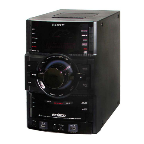
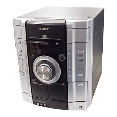
HCD-GN800
3
TABLE OF CONTENTS
1. SERVICING NOTES ................................................ 4
2. GENERAL
Location of Controls ....................................................... 5
3. DISASSEMBLY
3-1. Case ................................................................................. 8
3-2. Loading (Panel)............................................................... 8
3-3. Front Panel Assy ............................................................. 9
3-4. Tuner Pack, Sub Trans Board ......................................... 9
3-5. CD Mechanism Deck ...................................................... 10
3-6. Game In Board, Tape Mechanism Deck......................... 10
3-7. CD Switch Board, Display Board .................................. 11
3-8. Volume Board.................................................................. 11
3-9. Subwoofer Board, Rear Panel ........................................ 12
3-10. Main Board...................................................................... 12
3-11. Power Amp Board ........................................................... 13
3-12. SW Board, Driver Board................................................. 13
3-13. CD Board, CD Block Assy ............................................. 14
3-14. Sensor Board ................................................................... 14
3-15. Motor (TB) Board ........................................................... 15
3-16. Motor (LD) Board ........................................................... 15
4. TEST MODE.............................................................. 16
5. MECHANICAL ADJUSTMENTS....................... 20
6. ELECTRICAL ADJUSTMENTS
Deck section .................................................................... 20
CD Section ...................................................................... 22
7. DIAGRAMS
7-1. Circuit Board Location ................................................... 26
7-2. Block Diagram –CD Servo Section –........................... 28
Block Diagram –Tuner/Tape Deck Section –............... 29
Block Diagram –Main/Power Section –....................... 30
Block Diagram –Display Section –.............................. 31
7-3. Printed Wiring Board –CD Board –............................. 32
7-4. Schematic Diagram –CD Board –................................ 33
7-5. Printed Wiring Board –CD Mechanism Board –......... 34
7-6. Schematic Diagram –CD Mechanism Board –............ 35
7-7. Printed Wiring Boards –Main Board –......................... 36
7-8. Schematic Diagram –Main Board (1/3) –.................... 37
7-9. Schematic Diagram –Main Board (2/3) –.................... 38
7-10. Schematic Diagram –Main Board (3/3) –.................... 39
7-11. Printed Wiring Boards
–Game In, CD Switch Board –...................................... 40
7-12. Schematic Diagram
–Game In, CD Switch Board –...................................... 41
7-13. Printed Wiring Board –Display Board –...................... 42
7-14. Schematic Diagram –Display Board –......................... 43
7-15. Printed Wiring Board –Power Amp Board –................ 44
7-16. Schematic Diagram –Power Amp Board –.................. 45
7-17. Printed Wiring Board –Subwoofer Board –................. 46
7-18. Schematic Diagram –Subwoofer Board –.................... 47
7-19. Printed Wiring Boards –Trans Board –........................ 48
7-20. Schematic Diagram –Trans Board –............................. 49
7-21. IC Block Diagram ........................................................... 50
7-22. IC Pin Function Description ........................................... 51
8. EXPLODED VIEWS
8-1. Case, Rear Panel Section ................................................ 56
8-2. Front Panel Section ......................................................... 57
8-3. Chassis Section ............................................................... 58
8-4. CD Mechanism Deck Section-1
(CDM74-K6BD47S) ....................................................... 59
8-5. CD Mechanism Deck Section-2
(CDM74-K6BD47S) ....................................................... 60
9. ELECTRICAL PARTS LIST ............................... 61
