HCD-H66/H70/H77/H1200/H1400
|
Compact
Disc
Player
Section
System
Compact
disc
digital
audio
system
Semiconductor
laser
(A
=780nm)
Emission
duration
:
continuous
Max.
44.6uW*
*This
output
is
the
value
measured
at
distance
of
about
200
mm
from
the
objective
lens
surface
on
the
Optical
Pick-up
Block.
Laser
Laser
output
Cassette
Deck
Section
Recording
system
4-track
2-channel
stereo
Frequency
response
(DOLBY
NR
OFF)
40—13,000Hz
(+3dB),
using
TYPE
I
cassette
(Sony
HF-S)
40—14,000Hz
(+3dB),
using
TYPE
II
cassette
Wow
and
flutter
0.1%
WRMS
+0.3%
(DIN)
General
Power
requirements
AEP
model
220—230V
AC,
50/60Hz
UK
model:
240V
AC,
50Hz
G,
IT
model:
220—230V
AC,
50Hz
E,
EA,
AUS
model:
110-120V
or
220—240V
AC
adjustable,
50/60Hz
Power
consumption
Except
for
UK
model
:
90
watts
UK
model:
160
watts
Approx.
615X285
x
260mm
(w/h/d)
(24'/,X11'/,X10'/,
inches)
incl.
projecting
parts
and
controls
Weight
Appox.
11.6kg
(25
Ib
9
02)
Supplied
accessories
Remote
commander
(1)
Sony
SUM-3
(NS)
batteries
(2)
AM
loop
antenna
(1)
FM
lead
antenna
(1)
(HCD-H1200/H1
400)
Dimensions
Design
and
specifications
subject
to
change
without
notice.
Note:
G
—:
Germany
model
IT:
Italian
model
EA:
Saudi
Arabia
model
AUS:
Australian
model
For
HCD-H66/H77/H1200/H1400
CLASS
1
LASER
PRODUCT
This
appliance
is
classified
as
a
CLASS
1
LASER
product.
The
CLASS
1
LASER
PRODUCT
label
is
located
on
the
rear
exterior.
TABLE
OF
CONTENTS
Section
Title
Page
1.
SERVICING
NOTES
........................000
eee
3
2.
GENERAL
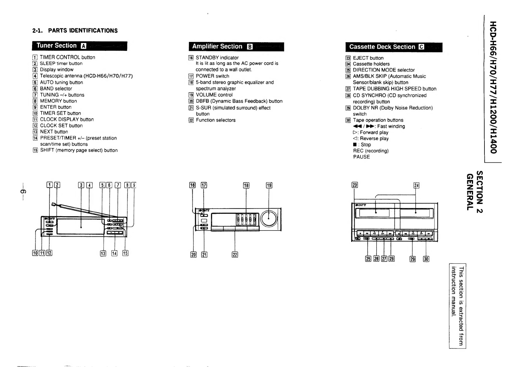
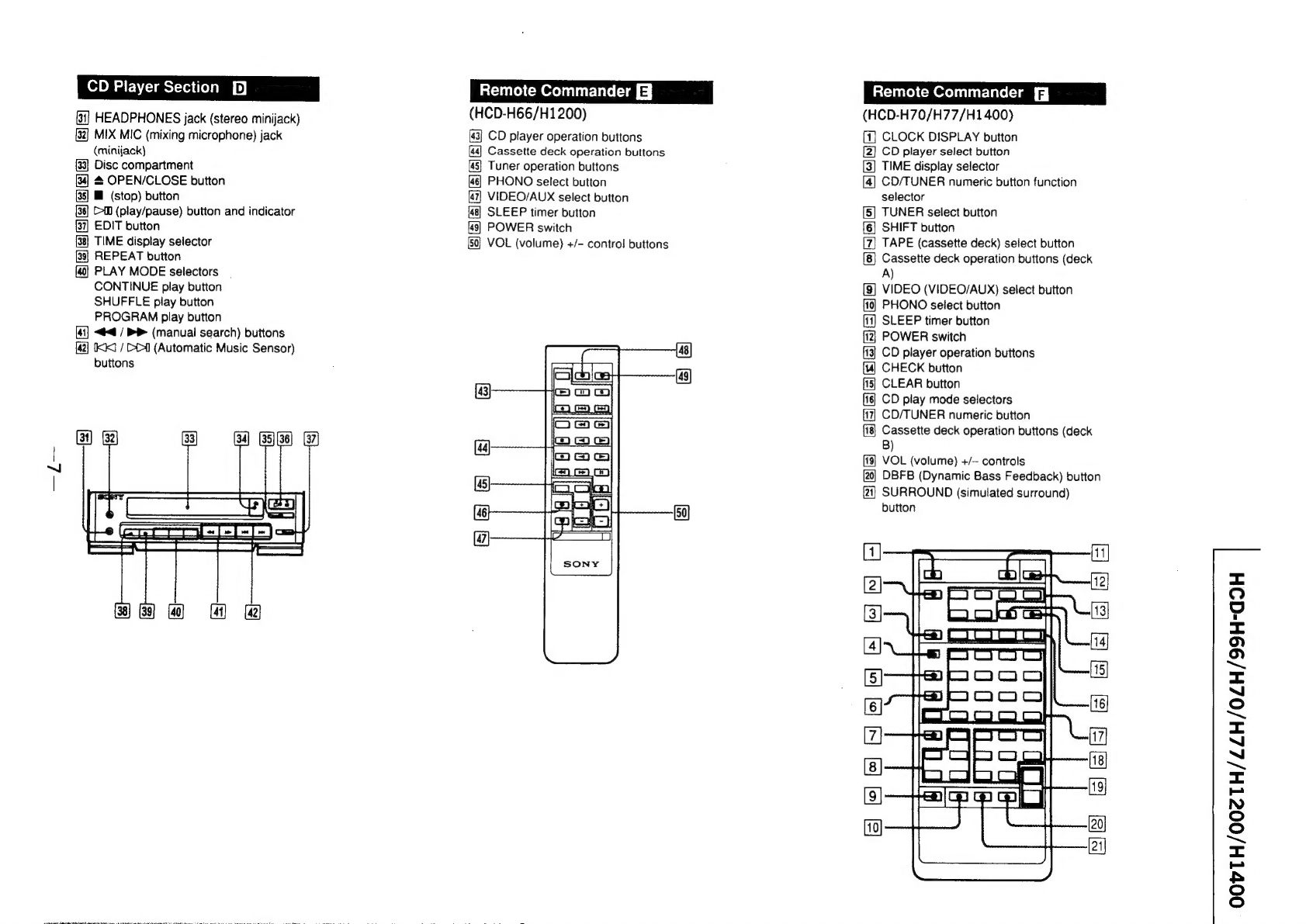
2-1.
Parts
Identifications
.............c
cece
cence
eee
eeee
6
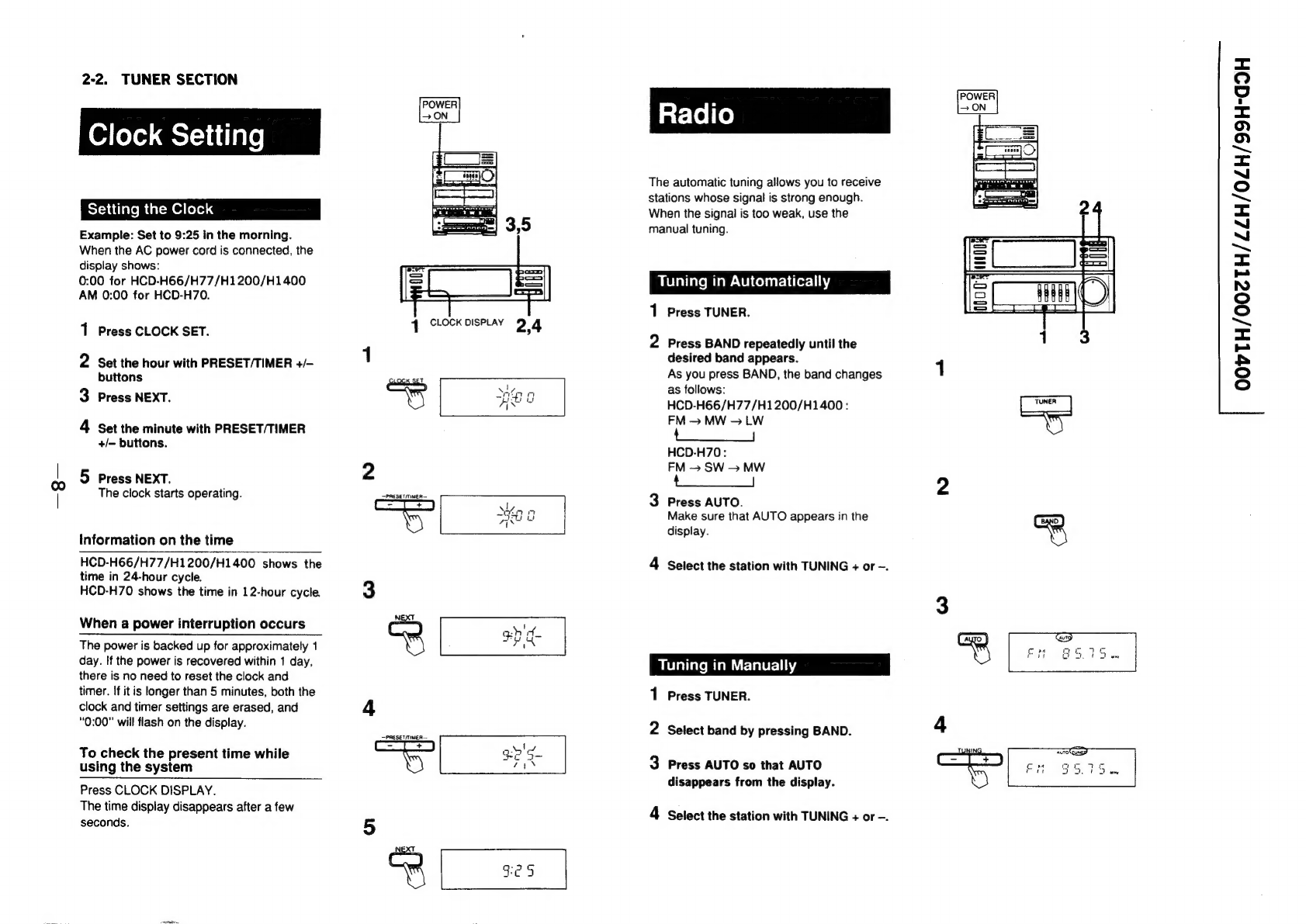
2-2.
Tumer
Section
........
0.0.0
cece
ccc
teen nnee
8
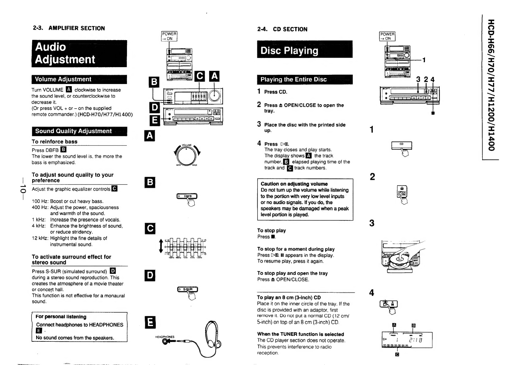
2-3.
Amplifier
Section
..........
0.0.00.
cece
eee
eee
ees
10
2-4:
CD
Section’
c.ncseeleee
ele
Marea
eS
10
2:5).
Deck<Section:
son305
fsieess
eves
bascieegeeds
steal
es
14
3.
DISASSEMBLY
Sed
CASE
reuse
vers
ateas
cubated
te
iat
sat
eo
tee
Gudea
Reh
ee
cab
Na
thid
21
3-2.
Power
Block
.........ccc
cece
sees
cc
eees
se
eeeenene
21
3-3.
“Main:
Boards
:ivesainas
suasck
vandis
ee
dea
ad
coda
dad
whee
21
3-4.
CD
Mechanism
Block
.............
0.
ee
eee
ee
eee
22
3-5.
TC
Mechanism
Block
................
eee
eee eee
22
3-6.
Display/SW/Jack/VR
Board..............
0.0000
22
4.
MECHANICAL
ADJUSTMENTS
..................
23
5.
ELECTRICAL
ADJUSTMENTS....................
23
6.
DIAGRAMS
6-1.
Semiconductor
Lead
Layouts..............
-.
see
e
ee
29
6-2.
Circuit
Boards
Location
..........
0.6.00
eee
eee
30
6-3.
Printed
Wiring
Boards
—Tuner/Deck/CD
Section—
...........06
cere
eee
32
6-4.
Schematic
Diagram—Tuner/Deck
Section—........
37
6-5.
Schematic
Diagram
—Power/Amplifier/Display
Section—......
........
41
6-6.
Printed
Wiring
Boards
—Power/Amplifier/Display
Section—......
........
45
6-7.
Schematic
Diagram—CD
Section—
................
48
6-8.
Pin
Functions
..........
0000s
eee
ca
eee
eee
enee
55
7.
EXPLODED
VIEWS
7-1.
Case,
Power
Section
..........0.cs
cece
cen
ee ee
eens
61
7-2.
Front
Panel,
Main
Board
Section..........-.....+.
62
7-3.
MD
Chassis
Section
..............
000
e
cee
eee
eee
ee
63
7-4,
Mechanism
Deck
Section
(1)
.........-..5
eee
eee
64
7-5.
Mechanism
Deck
Section
(2)
.........0000
eee
eeuee
65
7-6..
“CD!
Section:
()iesice%
pc
tan
asec
ananda
taed
dates
datas
66
lke
‘CD
Section:
(2)
mites
esi
Me
aad
ely
Deane
67
8.
ELECTRICAL
PARTS
LIST
.............
2.......
68
SAFETY-RELATED
COMPONENT
WARNNG!!
COMPONENTS
IDENTIFIED
BY
MARK
A
ORDOTTED
LINE
WITH
MARK
A
ON
THE
SCHEMATIC
De@&GRAMS
AND
IN
THE
PARTS
LIST
ARE
CRITICAL
TO
SAFE
OPERATION.
REPLACE
THESE
COMPONENTS
WITH
SONY
PARTS
WHOSE
PART
NUMBERS
AP
EAR
AS
SHOWN
IN
THIS
MANUAL
OR
IN
SUPPLEME)
‘TS
PUB-
LISHED
BY
SONY.