Sony HCD-XG60 User manual

SERVICE MANUAL
COMPACT DISC DECK RECEIVER
US Model
Canadian Model
AEP Model
UK Model
HCD-XG500
E Model
HCD-XG60
SPECIFICATIONS
HCD-XG60/XG500
Photo: HCD-XG60
Ver 1.0 2001.02
9-929-577-11 Sony Corporation
2001B0500-1 Audio Entertainment Group
C2001.2 General Engineering Dept.
HCD-XG60/XG500 is the amplifier, CD
player, tape deck and tuner section in
LBT-XG60/XG500.
Dolby noise reduction manufactured under license
from Dolby Laboratories Licensing Corporation.
“DOLBY” and the double-D symbol ;are trade-
marks of Dolby Laboratories Licensing Corporation.
Model Name Using Similar Mechanism HCD-LX6/LX50/LX70
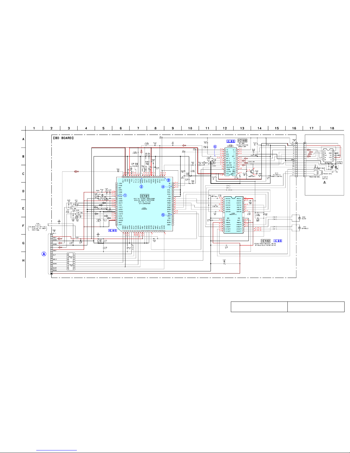
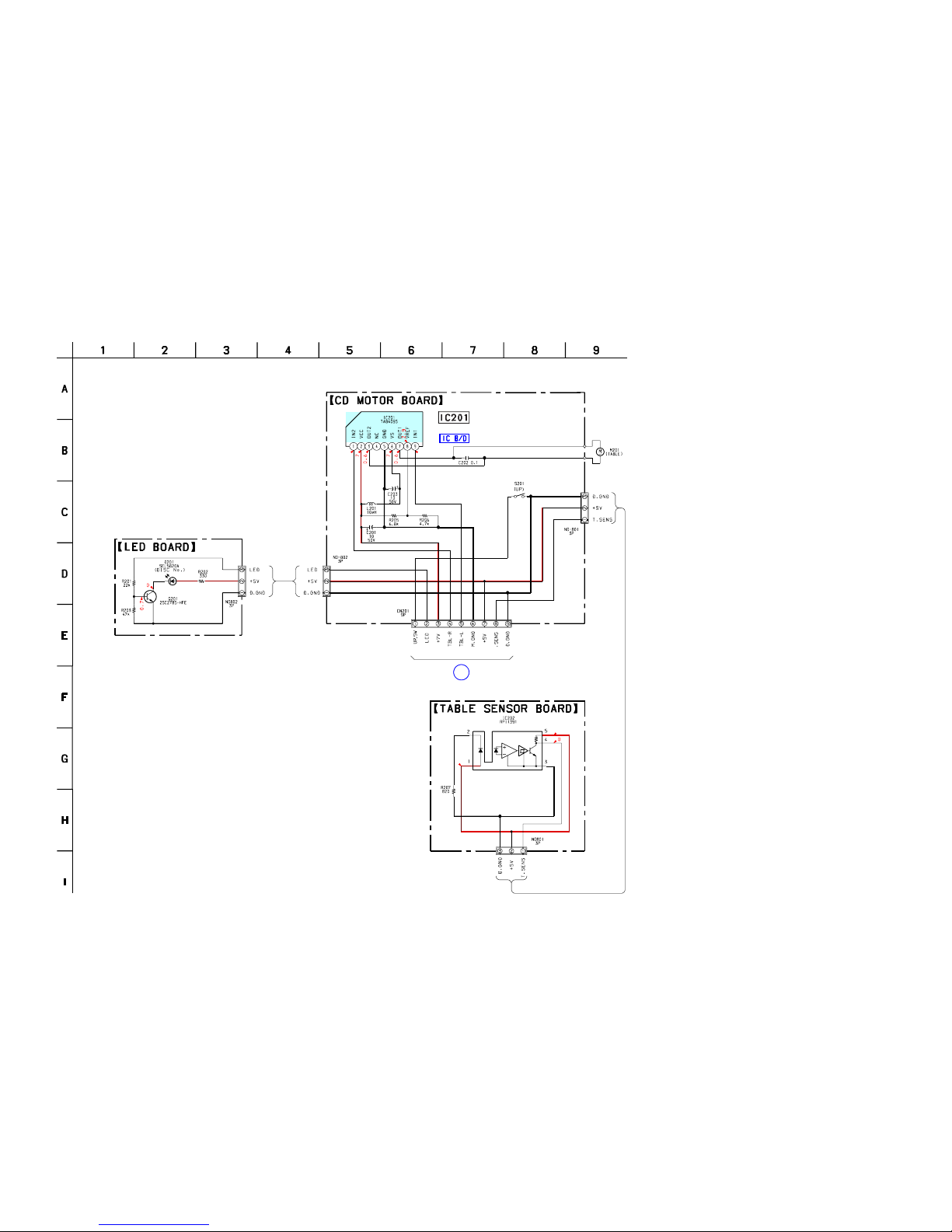
CD CD Mechanism Type CDM37M-5BD32L
Section Base Unit Name BU-5BD32L
Optical Pick-up Name KSS-213DH
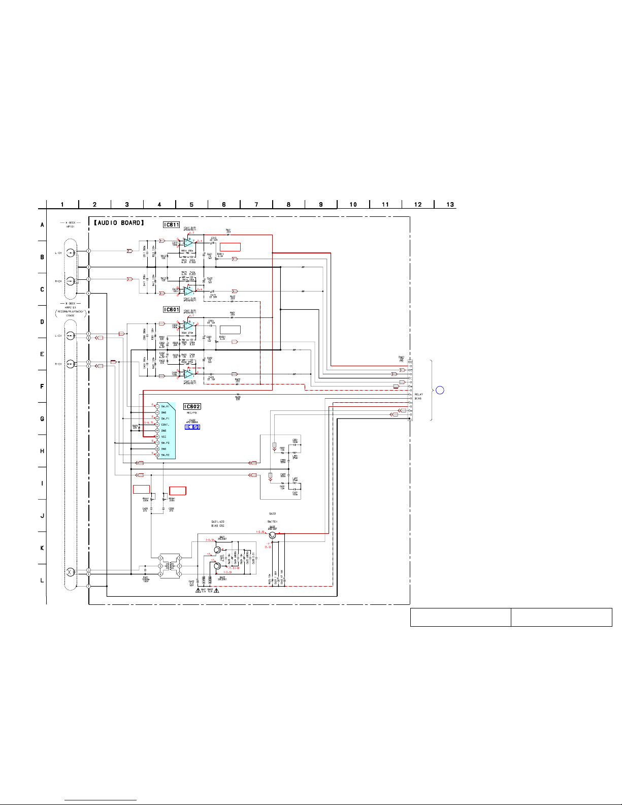
TAPE Model Name Using Similar Mechanism NEW
Section Tape Transport Mechanism Type TCM-230PWR42
AUDIO POWER SPECIFICATIONS:
(US model only)
POWER OUTPUT AND TOTAL
HARMONIC DISTORTION
With 6 ohm loads both channels driven, from
120-10,000 Hz; rates 140 watts per channel
minimum RMS power, with no more than 10%
total harmonic distortion.
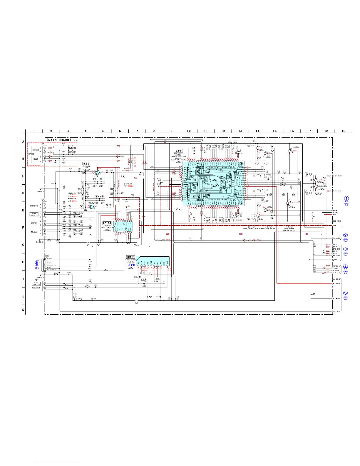
Amplifier section
Canadian model:
Continuous RMS power output (reference)
160 + 160 watts (6 ohms at
1 kHz, 10% THD)
Total harmonic distortion less than 0.07%
(6 ohms at 1 kHz, 70 W)
AEP, UK models:
DIN power output (rated) 110 + 110 watts
(6 ohms at 1 kHz, DIN)
Continuous RMS power output (reference)
140 + 140 watts
(6 ohms at 1 kHz, 10% THD)
Music power output (reference)
240 + 240 watts
(6 ohms at 1 kHz, 10% THD)
Other models:
The following measured at AC 120/220/240V, 50 Hz
DIN power output (rated) 150 + 150 watts
(6 ohms at 1 kHz, DIN)
Continuous RMS power output (reference)
200 + 200 watts
(6 ohms at 1 kHz, 10% THD)
Inputs
DJ MIX*:
(phono jacks) sensitivity 250 mV,
impedance 47 kilohms
GUITAR IN:
(phone jack) sensitivity 75 mV,
impedance 470 kilohms
PHONO IN:
(phono jacks) sensitivity 3 mV,
impedance 47 kilohms
MIX MIC:
(phone jack) sensitivity 1 mV,
impedance 10 kilohms
VIDEO IN:
(phono jacks) sensitivity 250 mV,
impedance 47 kilohms
GAME IN:
(phono jacks) sensitivity 250 mV,
impedance 47 kilohms
MD IN:
(phono jack) sensitivity 450 mV,
impedance 47 kilohms
Outputs
DJ MIX*:
(phono jacks) sensitivity 250 mV,
impedance 1 kilohms
PHONES:
(stereo phone jack) accepts headphones of 8
ohms or more
VIDEO OUT:
(phono jack) voltage 250 mV
impedance 1 kilohm
MD OUT:
(phono jacks) voltage 250 mV
impedance 1 kilohm
FRONT SPEAKER: accepts impedance of 6 to
16 ohms
* US, Canadian, AEP, UK, and Mexican models
only
CD player section
System Compact disc and digital
audio system
Laser Semiconductor laser
(λ=780nm), Emission
duration: continuous
Wavelength 780 – 790 nm
Frequency response 2 Hz – 20 kHz (±0.5 dB)
Signal-to-noise ratio More than 90 dB
Dynamic range More than 90 dB
CD OPTICAL DIGITAL OUT
(Square optical connector jack, rear panel)
Wavelength: 660 nm
Output level –18 dBm
– Continued on next page –

13
HCD-XG60/XG500
[CD Delivery Mode]
• This mode moves the optical pick-up to the position durable to
vibration. Use this mode when returning the set to the customer
after repair.
Procedure:
1. Press the ?/1button to turn the power ON.
2. Press the [LOOP] and ?/1buttons simultaneously.
3. A message “LOCK” is displayed on the fluorescent indicator
tube, and the CD delivery mode is set.
[LED and Fluorescent IndicatorTube All Lit, Key Check
Mode]
Procedure:
1. Press three buttons of [ /CLOCK SET], [ENTER/NEXT],
and [DISC 2] simultaneously.
2. LEDs and fluorescent indicator tube are all turned on.
Press the [DISC 2] button, and the key check mode is acti-
vated.
3. In the key check mode, the fluorescent indicator tube displays
“K 0 J0 V0”. Each time a button is pressed, “K” value in-
creases. However, once a button is pressed, it is no longer taken
into account.
“J” value increases like 1, 2, 3 ... if turn the JOG dial clock-
wise, or it decreases like 0, 9, 8 ... if turn the JOG dial counter-
clockwise.
“V” value increases like 1, 2, 3 ... if turn the [VOLUME] dial
clockwise, or it decreases like 0, 9, 8 ... if turn the JOG dial
counterclockwise.
4. To release from this mode, press three buttons in the same
manner as step 1, or disconnect the power cord.
c
[MC Cold Reset]
• The cold reset clears all data including preset data stored in the
RAM to initial conditions. Execute this mode when returning
the set to the customer.
Procedure:
1. Turn the power ON or set to the DEMO mode.
2. Press three buttons of [ /CLOCK SET], [ENTER/NEXT], and
?/1simultaneously.
3. The set is reset, and displays “COLD RESET”, then becomes
DEMO mode.
[MC Hot Reset]
• This mode resets the set with the preset data kept stored in the
memory. The hot reset mode functions same as if the power
cord is plugged in and out.
Procedure:
1. Turn the power ON or set to the DEMO mode.
2. Press three buttons of [ /CLOCK SET], [ENTER/NEXT],
and [DISC 1] simultaneously.
3. The set is reset, and becomes standby state.
[Change-over the AMTuning Interval]
(EXCEPT AEP, UK, and Saudi Arabia models)
• The AM tuning interval can be changed over 9 kHz or 10 kHz.
Procedure:
1. Press the ?/1button to turn the power ON.
2. Select the function “TUNER”, and press the [TUNER/BAND]
button to select the BAND “AM”.
3. Press the ?/1button to turn the power OFF.
4. Press the [ENTER/NEXT] and ?/1buttons simultaneously,
and the display on the fluorescent indicator tube changes to
“AM 9 K STEP” or “AM 10 K STEP”, and thus the tuning
interval is changed over.
c
SECTION 4
TEST MODE
c

14
HCD-XG60/XG500
[Aging Mode]
This mode can be used for operation check of tape deck section.
Tape deck section work in parallel.
• If an error occurred:
The aging operation stops and display then status.
• If no error occurs:
The aging operation continues repeatedly.
Procedure:
1. Load the tapes into the decks A and B respectively.
2. Press the [FUNCTION] button to select the function “CD”.
3. Press the [PLAY MODE] button to set the “ALL DISCS” mode,
and press the [REPEAT] button to “REPEAT” off.
4. Press three buttons of [ /CLOCK SET], [ENTER/NEXT],
and [DISC 4] simultaneously.
5. The aging mode is activated, if the indicator of disc tray num-
ber on the fluorescent indicator tube is blinking.
6. To release from the aging mode, press the ?/1button to turn
the power OFF and operate the cold reset. (Refer to the “MC
Cold Reset”)
1. Display at the Aging Mode
• Display operating state of tape deck section alternately.
• If an error occurred, stop display.
2. Tape Deck Section
• The sequence during the aging mode is following as below.
• If an error occurred, stop display that step.
Aging mode sequence (Tape deck section) :
Rewind the tape A and B
“TAPE A AG-1”
Shut off
FWD play the tape A
“TAPE A AG-2”
2 minutes
Fast forward the tape A
“TAPE A AG-3”
Shut off or 20 seconds
REV play the tape A
“TAPE A AG-4”
2 minutes
Rewind the tape A
“TAPE A AG-5”
Shut off
FWD play the tape B
“TAPE B AG-2”
2 minutes
Fast forward the tape B
“TAPE B AG-3”
Shut off or 20 seconds
REV play the tape B
“TAPE B AG-4”
2 minutes
Rewind the tape B
“TAPE B AG-5”
Shut off
Note: “TAPE *AG-*” is display of each step.
c

HCD-XG60/XG500
2525
7-7. SCHEMATIC DIAGRAM – BD Board – • See page 35 for Waveforms. •See page 47 for IC Block Diagrams.
MAIN
BOARD
CN411
D+5V (SW)
L-CH
R-CH
A+5V (SW)
CD-DATA
CD-CLK
SQ-DATA
SQ-CLK
M+7V (UNSW)
OPTICAL PICK-UP
BLOCK
(KSS-213DH)
2.2
•Voltages and waveforms are dc with respect to ground
under no-signal conditions.
no mark :CD STOP
( ) : CD PLAY
The components identified by mark 0or dotted
line with mark 0are critical for safety.
Replaceonly withpart number specified.
Lescomposants identifiésparune marque0sont
critiques pourla sécurité. Neles remplacerque
par une pièce portant le numéro spécifié.
(Page 32)

HCD-XG60/XG500
2727
7-9. SCHEMATIC DIAGRAM –CD MOTOR Section –•See page 47 for IC Block Diagram.
B
MAIN BOARD
CN412
4.8
4.8
4.8
4.8
LED DRIVE
TABLE MOTOR DRIVER
DISC TABLE SENSOR
TRAY
•Voltages and waveforms are dc with respect to ground
under no-signal conditions.
no mark :CD STOP
(Page 32)

HCD-XG60/XG500
2929
7-11. SCHEMATIC DIAGRAM – AUDIO Board – • See page 47 for IC Block Diagram.
C
MAIN BOARD
CN303
PB LEVEL (L)
(DECK A)
PB LEVEL (L)
(DECK B)
REC BIAS (L)
(DECK B)
REC BIAS (R)
(DECK B)
–7
–7
6.9
6.9–6.5
–6.5
–6.5
–6.5 (–7.2)
(PALYBACK) PB EQ AMP
(DECK A)
PB EQ AMP
(DECK B)
SWITCHING
T621
BIAS OSC
REC BIAS
NC
A+7.5V
APB-LCH
APB-RCH
AGND
BPB-LCH
BPB-RCH
A–7.5V
–VBIAS (–7.5V)
+VBIAS (+7.5V)
BREC-RCH
BREC-LCH
TC-HEAD-GND
R492 1.5K
R491 820
R482 1.5K
R481 820
• Voltages and waveforms are dc with respect to ground
under no-signal conditions.
no mark :TAPE PLAY
( ) : RECORD
The components identified by mark 0or dotted
line with mark 0are critical for safety.
Replaceonly withpart number specified.
Lescomposants identifiéspar une marque0sont
critiques pourla sécurité. Neles remplacerque
par une pièce portant le numéro spécifié.
(Page 32)

HCD-XG60/XG500
3030
7-12. PRINTED WIRING BOARD – LEAF SW Board – • See page 23 for Circuit Boards Location.
D
MAIN BOARD
CN304
*(3.7) *
4.5
( )
DECK B
PLUNGER
DECK A
PLUNGER
(CAPSTAN)
(DECK A 120/70)
(DECK A HALF)
(DECK A REC)
(DECK B HALF)
(DECK B REC)
(DECK B 120/70)
ROTATION DETECT SENSOR
(DECK A)
ROTATION DETECT
SENSOR (DECK B)
(DECK A PLAY) (DECK B PLAY)
CONTROL SWITCH
CAPM–
CAPM+
CAPM–H/L
A–TRGM
TRGM–GND
B–TRGM
A–SHUT
DGND
A–HALF
+5V
A–120/70
B–SHUT
A–PLAY
B–HALF / REC–A / REC–B
B–120/70
B–PALY
NC
7.5k
7-13. SCHEMATIC DIAGRAM – LEAF SW Board –
• Voltages and waveforms are dc with respect to ground
under no-signal conditions.
no mark :TAPE PLAY (DECK A)
( ) :TAPE PLAY (DECK B)
∗: Impossible to measure
DECK A
PLUNGER
DECK B
PLUNGER
(DECK A PLAY)
(DECK A HALF) (DECK A 120/70) (DECK A REC)
MAIN BOARD
CN304
(DECK B HALF)
(DECK B PLAY)
(DECK B 120/70)
(DECK B REC)
11
11
D
4
12
34
12
3
()
1-676-219-
(Page 34)
(Page 32)

HCD-XG60/XG500
3131
7-14. SCHEMATIC DIAGRAM – MAIN Board (1/3) – • See page 47 for IC Block Diagram.
• Voltages and waveforms are dc with respect to ground
under no-signal (detuned) conditions.
no mark :TUNER (FM/AM)
( ) :VIDEO
(Page 39)
(Page 33)
(Page 32)
(Page 32)
(Page 32)
(Page 33)

HCD-XG60/XG500
3232
7-15. SCHEMATIC DIAGRAM – MAIN Board (2/3) – • See page 35 forWaveforms.
• Voltages and waveforms are dc with respect to ground
under no-signal (detuned) conditions.
no mark :TUNER (FM/AM)
( ) : CD PLAY
< > :VIDEO
{} :TAPE PLAY (DECK A)
[ ] :TAPE PLAY (DECK B)
〈〈 〉〉 : RECORD
∗: Impossible to measure
(Page 31)
(Page 29) (Page 30)
(Page 33) (Page 31)
(Page
33)
(Page 27)
(Page 25)
(Page 41)
(Page 33)
(Page 31)
(Page 33)

HCD-XG60/XG500
3333
7-16. SCHEMATIC DIAGRAM – MAIN Board (3/3) –
• Voltages and waveforms are dc with respect to ground
under no-signal (detuned) conditions.
no mark :TUNER (FM/AM)
( ) : CD PLAY
(Page 32)
(Page 32)
(Page 32)
(Page 31)
(Page 37)
(Page 37)
(Page 32)
(Page 31)
(Page 39)

HCD-XG60/XG500
3535
Thereare afewcases thatthe part isn't mountedin model
is printed on diagrams.
• Semiconductor
Location
Ref. No. Location
D191 C-8
D192 C-8
D193 B-8
D194 C-8
D501 J-8
D534 H-8
D801 J-8
D802 I-9
D803 I-9
D804 J-9
D805 I-9
D806 I-8
D807 J-10
D808 J-7
D911 F-11
D912 G-11
D913 G-11
D931 H-11
D951 C-12
IC101 E-5
IC181 C-7
IC191 C-8
IC301 H-4
IC501 H-7
IC601 C-3
IC781 B-13
IC801 J-9
IC901 D-12
IC911 F-11
IC931 H-12
IC932 H-12
IC933 I-12
IC951 C-12
Q111 E-7
Q112 E-7
Q113 E-7
Q115 E-6
Q161 E-6
Q162 F-6
Q163 F-6
Q165 F-5
Q331 J-4
Q332 J-4
Q333 J-4
Q334 J-4
Q335 J-5
Q336 J-4
Q339 J-5
Q801 I-8
Q802 J-10
Q803 J-10
Q804 I-10
Q901 D-13
Q902 C-13
Q903 C-12
Q904 C-12
Q905 C-13
Q906 C-13
Q911 G-11
Q912 F-11
Q913 G-11
Q914 G-11
Q931 H-11
Q932 H-11
Q961 B-12
Q962 B-12
• Waveforms
– BD Board –
1IC101 yj (XTAO) 5IC101 wh (MDP) (CD Play Mode)
2IC101 ta (RFAC) (CD Play Mode)
3IC101 ra (TE) (CD Play Mode)
4IC101 el (FE) (CD Play Mode)
6IC103 qh (RFO) (CD Play Mode) 2IC501 qg (X-IN)
– MAIN Board –
1IC501 0(XC-IN)
3.1 Vp-p
59 ns
1.2 Vp-p
0.2 Vp-p
0.5 Vp-p
2.5 Vp-p
7.8 µs
1.3 Vp-p
1.8 Vp-p
30.5 µs
1.8 Vp-p
62.5 ns
– PANEL FL Board –
1IC601 u; (XIN)
3.7 Vp-p
80 ns

HCD-XG60/XG500
3737
7-19. SCHEMATIC DIAGRAM – PA Board –
• Voltages and waveforms are dc with respect to ground
under no-signal (detuned) conditions.
no mark :TUNER (FM/AM)
The components identified by mark 0or dotted
line with mark 0are critical for safety.
Replaceonly withpart number specified.
Lescomposants identifiéspar une marque0sont
critiques pourla sécurité. Neles remplacerque
par une pièce portant le numéro spécifié.
(Page 46)
(Page
46)
(Page
33) (Page 33)
(Page 46)
(Page 39)

HCD-XG60/XG500
3939
7-21. SCHEMATIC DIAGRAM – MIC/FRONT INPUT/HEADPHONES Boards –
• Voltages and waveforms are dc with respect to ground
under no-signal (detuned) conditions.
no mark :TUNER (FM/AM)
(Page 45)
(Page 33)
(Page 31)
(Page 37)

HCD-XG60/XG500
4141
7-23. SCHEMATIC DIAGRAM – PANEL FL Board – • See page 35 forWaveform. •See page 47 for IC Block Diagram.
•Voltages and waveforms are dc with respect to ground
under no-signal (detuned) conditions.
no mark :TUNER (FM/AM)
(Page 45)
(Page 45)
(Page 32)
(Page 43)

HCD-XG60/XG500
4343
7-25. SCHEMATIC DIAGRAM – PANEL VR/ILLUMINATION Boards – • See page 47 for IC Block Diagram.
•Voltages and waveforms are dc with respect to ground
under no-signal (detuned) conditions.
no mark :TUNER (FM/AM)
(Page 41)

HCD-XG60/XG500
4545
7-27. SCHEMATIC DIAGRAM – TC-A/TC-B/CD-L/CD-R (1)/CD-R (2) Boards –
(Page 39)
(Page 41)
(Page 41)

HCD-XG60/XG500
4646
7-28. PRINTED WIRING BOARDS –TRANSFORMER Section–
•See page 23 for Circuit Boards Location.
The components identified by mark 0or dotted
line with mark 0are critical for safety.
Replaceonly withpart number specified.
Lescomposants identifiéspar une marque0sont
critiques pourla sécurité. Neles remplacerque
par une pièce portant le numéro spécifié.
7-29. SCHEMATIC DIAGRAM –TRANSFORMER Section –
TRANS BOARD
(E2, EA, SP, AR)
(EXCEPT US, CND, MX)
(US, CND, MX)
(AEP, UK)
(E2, EA, SP, AR)
1
4
(XG60)
1
3
L
PA BOARD
NO702
M
PA BOARD
CN801
(XG60)
4
1
**
NOT REPLACE:
BULT IN TRANSFORMER
T951
POWER
TRANSFORMER
1-680-174- (11)
11
(US, CND)
SUB TRANS BOARD
T901
SUB POWER
TRANSFORMER
14
QPA BOARD
CN904
1
2
1 2
AC IN
(E2, EA, SP, AR)
(US, CND, AEP, UK, MX)
–1–2 (US, CND, MX)
(AEP, UK)
VOLTAGE
SELECTOR
S901
120V
R
220V
R
230V – 240V
(E2, EA, SP, AR)
14
(E2, EA, SP, AR)
1-680-175- (11)
11
(Page 36)
(Page 36)
(Page 36)
(Page 37)
(Page 37)
(Page 37)
Other manuals for HCD-XG60
1
This manual suits for next models
1
Table of contents
Other Sony Stereo System manuals

Sony
Sony CMT-DX400 User manual

Sony
Sony HCD-DR8AV User manual

Sony
Sony HCD-GX45 - System Components User manual

Sony
Sony MHC-GS200 User manual

Sony
Sony MHC-M20D User manual

Sony
Sony HT-CT290 User manual

Sony
Sony CMT-NEZ5 User manual

Sony
Sony GX255 User manual

Sony
Sony MDR-F130K User manual

Sony
Sony CMT-DX400A User manual