Sony SRS-X7 User manual

SERVICE MANUAL
Sony Corporation
Published by Sony Techno Create Corporation
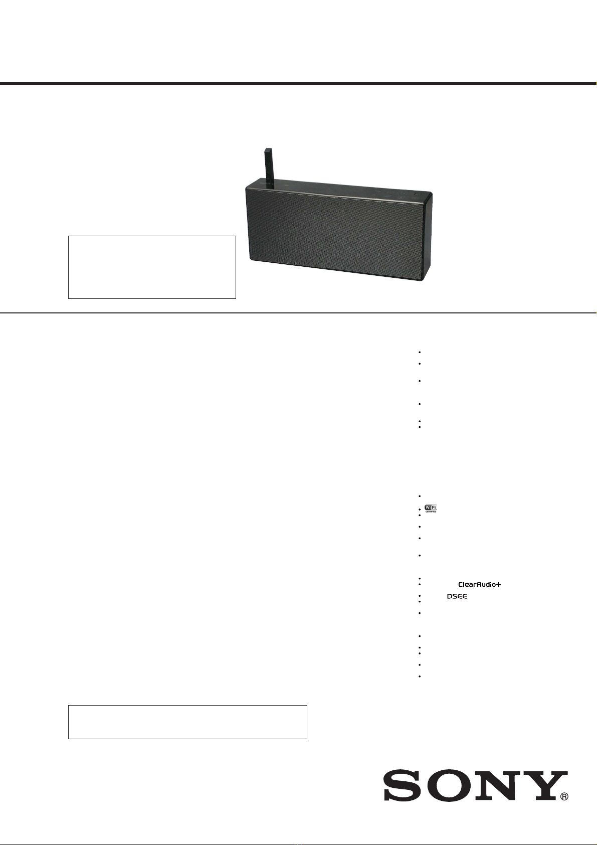
SRS-X7
SPECIFICATIONS
PERSONAL AUDIO SYSTEM
9-893-945-03
2014C33-1
© 2014.03
US Model
Canadian Model
AEP Model
UK Model
Australian Model
Singapore Model
Korean Model
Ver. 1.2 2014.03
Note:
Be sure to keep your PC used for service and
checking of this unit always updated with the
latest version of your anti-virus software.
In case a virus affected unit was found during
service, contact your Service Headquarters.
CAUTION
Danger of explosion if battery is incorrectly replaced.
Replace only with the same or equivalent type.
Section for Speaker
Speakers
Full range speak er: Approx. 46 mm (1 7/8 inches) diameter × 2/
Subwoofer: Approx. 62 mm (2 3/8 inches) diameter × 1
Section for Amplier
POWER OUTPUT AND TOTAL HARMONIC DISTORTION:
Power Output (reference)
Using AC adaptor
Full range speak er: 8W+8W (at 1% harmonic distortion, 1 kHz,8 Ω)
Subwoofer: 16W (at 1% harmonic distortion,100 Hz, 4 Ω)
Using battery
Full range speak er: 3W+3W (at 1% harmonic distortion, 1 kHz, 8 Ω)
Subwoofer: 6W (at 1% harmonic distortion, 100 Hz, 4 Ω)
Section for Network
Compatible standards
IEEE 802.11 b/g (WEP 64 bit, WEP 128 bit, WPA/WP A2-PSK (AES), WPA/
WPA2-PSK (TKIP))
Radio frequency (US and Canadian models)
2.412 GHz – 2.462 GHz (2.4 GHz ISM Band, 11 Channels)/Channel 1
– Channel 11
Radio frequency (Except US and Canadian models)
2.412 GHz – 2.472 GHz (2.4 GHz ISM Band, 13 Channels)/Channel 1
– Channel 13
Section for BLUETOOTH
Output
BLUETOOTH Specication Power Class 2
Maximum communication range
Line of sight Approx. 10 m*1
Radio frequency
2.4 GHz band (2.4 000 GHz – 2.4835 GHz)
Communication System
BLUETOOTH Specication Version 3.0
Compatible BLUETOOTH Proles*2
A2DP (Advanced Audio Distribution Prole)/A VRCP (Audio Video
Remote Control Prole)
Supported codec*3
SBC (Subband Codec)*4/AA C*5/aptX
Transmission bandwidth (A2DP)
20 Hz – 20,000 Hz (with 44. 1 kHz sampling)
*1The actual range will vary depending on factors such as obstacles
between devices, magnetic elds ar ound a microwave oven, static
electricity, reception sensitivity, aerial’s performance, operating
system, software application, etc.
*2BLUETOOTH standard proles indicate the purpose of BLUET OOTH
communication between devic es.
*3Codec: Audio signal compression and conversion format
*4Subband Codec
*5Advanced Audio Coding
General
AUDIO IN
ANALOG Φ 3.5 mm ster eo mini jack
Network port
10BASE-T/ 100BASE-TX (Auto Polarity)
DC OUT
USB jack Type A (for charging the battery of a connected device) (5 V,
Max. 1.5 A: labeled on bottom of system)
Power (US, Canadian, AEP, UK and Singapore models)
DC 18V (using the supplied AC adaptor connected to AC 100V-240V,
50Hz/60Hz power supply) or, using built in lithium-ion battery
Power (Australian, Russian and Korean models)
DC 18V (using the supplied AC adaptor connected to AC 120V-240V,
50Hz/60Hz power supply) or, using built in lithium-ion battery
Usage life of lithium-ion battery (when the NETW ORK
OFF/ON switch is OFF)
Approx. 6 hours
Usage life of lithium-ion battery (when the NETW ORK
OFF/ON switch is ON)
Approx. 3 hours
Operating temperature
5 °C to 35 °C (41 °F to 95 °F)
Dimensions (w/h/d) (including pr ojecting parts and
controls)
Approx. 300 mm × 132 mm × 60 mm (11 7/8 inches × 5 2/8 inches ×
23/8 inches)
Mass
Approx. 1.9kg (4 lb 3 oz)
Supplied accessories:
AC power cord (1)/ AC adaptor (AC-E1826L) (US, Canadian, AEP, UK and
Singapore models) (1) / AC adaptor (AC-E1826) (Australian, Russian and
Korean models) (1)/ Start Guide “Enjoy Music over Your Wi-Fi Network”/
Reference Guide, warranty card (US model) / Reference Guide (Except US
model) / Warranty card (Except Singapore model)
Design and specications are subject to change without notice.
On Copyrights
SONY, Sony Entertainment Network and the logos ar e trademarks
of Sony Corporation.
Windows, the Windows logo , and Windows Media ar e either
registered trademarks or trademarks of Micr osoft Corporation in
the United States and/or other c ountries.
This product is protected by certain intellectual property rights of
Microsoft Corporation. Use or distribution of such technology
outside of this product is prohibited without a license from
Microsoft or an authorized Microsoft subsidiar y.
Pandora, the Pandora logo, and the Pandora trade dress are
trademarks or r egistered trademarks of P andora Media, Inc., used
with permission.
Spotify and Spotify logos are trademarks of the Spotify Gr oup.
Apple, the Apple logo, AirPlay, iPad, iPhone, iPod, iPod nano, iPod
touch, iTunes, Mac, and OS X are trademarks of Apple Inc.,
registered in the U.S. and other countries. App Store is a ser vice
mark of Apple Inc.
“Made f or iPod,” “Made f or iPhone,” and “Made for iPad” mean that
an electronic accessory has been designed to c onnect specically
to iPod, iPhone, or iPad, respectively, and has been certied by the
developer to meet Apple perf ormance standar ds. Apple is not
responsible for the operation of this device or its compliance with
safety and regulatory standards. Please note that the use of this
accessory with iPod, iPhone, or iPad may a ect wireless
performance.
Macintosh and Mac OS ar e trademarks of Apple Inc., registered in
the U.S. and other countries.
“” is a mark of the Wi-Fi Allianc e.
Wi-Fi®, Wi-Fi Protected Access® and Wi-Fi Allianc e® are registered
marks of the Wi-Fi Allianc e.
Wi-Fi CERTIFIED™, WPA™ , WPA2™ and Wi-Fi Protected Setup™ ar e
marks of the Wi-Fi Allianc e.
DLNA™, the DLNA Logo and DLNA CERTIFIED™ ar e trademarks,
service marks, or certication marks of the Digital Living Network
Alliance.
© 2013 CSR plc and its group companies.
The aptX® mark and the aptX logo ar e trade marks of CSR plc or
one of its group companies and may be r egistered in one or mor e
jurisdictions.
“S-Master” is a trademark of Sony C orporation.
ClearAudio+ and are trademarks of Sony
Corporation.
“DSEE” and are trademarks of Sony C orporation.
MPEG Layer-3 audio coding technology and patents licensed from
Fraunhofer IIS and Thomson.
The BLUETOOTH® word mark and logos ar e owned by the
Bluetooth SIG, Inc. and any use of such marks by Sony C orporation
is under license. Other trademarks and tr ade names ar e those of
their respective owners.
The N Mark is a trademark or r egistered trademark of NFC Forum,
Inc. in the United States and in other countries.
Google Play and Andr oid are trademarks of Google Inc.
“Xperia” and “Xperia Tablet” are trademarks of Sony Mobile
Communications AB.
WALKMAN® and W ALKMAN® logo are registered trademarks of
Sony Corporation.
The system names and pr oduct names indicated in this manual ar e
generally the trademarks or registered trademarks of the
manufacturer.
™ and ® marks ar e omitted in this manual.

SRS-X7
2
1. SERVICING NOTES ............................................. 3
2. DISASSEMBLY
2-1. Disassembly Flow........................................................... 9
2-2. Panel (Bottom) Block ..................................................... 10
2-3. Lithium Battery (BAT1).................................................. 11
2-4. Net Grill Sub Assy .......................................................... 12
2-5. Panel Top Assy................................................................ 13
2-6. Cabinet (Front) Assy....................................................... 14
2-7. Clamp (L35).................................................................... 15
2-8. Box (Lch, Rch) Block..................................................... 16
2-9. Loudspeaker Passive (L-ch, R-ch) (SP4, SP5) ............... 16
2-10. Loudspeaker (6.2 cm) (Subwoofer) (SP3)...................... 17
2-11. Loudspeaker (4.6 cm) Block........................................... 17
2-12. Loudspeaker (4.6 cm) (Full Range Speaker)
(L-ch, R-ch) (SP1, SP2).................................................. 18
2-13. Antenna Assy (ANT1) .................................................... 19
2-14. TOUCH Board................................................................ 20
2-15. KEY Board...................................................................... 21
2-16. NFC Module (RC-S801) (NFC1) ................................... 22
2-17. Cover (Jack) Block ......................................................... 23
2-18. CHARGE Board ............................................................. 24
2-19. JACK Board.................................................................... 24
2-20. MAIN Board Block ........................................................ 25
2-21. WiFi Module (WIFI1), MAIN Board ............................. 25
2-22. Bluetooth Module (BT1) ................................................ 26
2-23. How to Bend Flexible Flat Cable ................................... 26
3. TEST MODE ............................................................ 27
4. DIAGRAMS
4-1. Block Diagram - MAIN Section -................................... 29
4-2. Block Diagram
- PANEL, POWER SUPPLY Section -........................... 30
4-3. Printed Wiring Boards - MAIN Section (1/2) - .............. 32
4-4. Printed Wiring Boards - MAIN Section (2/2) - .............. 33
4-5. Schematic Diagram - MAIN Section (1/4) -................... 34
4-6. Schematic Diagram - MAIN Section (2/4) -................... 35
4-7. Schematic Diagram - MAIN Section (3/4) -................... 36
4-8. Schematic Diagram - MAIN Section (4/4) -................... 37
5. EXPLODED VIEWS
5-1. Overall Section ............................................................... 45
5-2. Full Range Speaker Section............................................ 46
5-3. Cabinet (Front) Section................................................... 47
5-4. TOUCH Board, JACK Board Section ............................ 48
5-5. Cabinet Rear Section ...................................................... 49
6. ELECTRICAL PARTS LIST .............................. 50
Accessories are given in the last of the electrical parts list.
TABLE OF CONTENTS
NOTES ON CHIP COMPONENT REPLACEMENT
• Never reuse a disconnected chip component.
• Notice that the minus side of a tantalum capacitor may be dam-
aged by heat.
SAFETY-RELATED COMPONENT WARNING!
COMPONENTS IDENTIFIED BY MARK 0OR DOTTED LINE
WITH MARK 0ON THE SCHEMATIC DIAGRAMS AND IN
THE PARTS LIST ARE CRITICAL TO SAFE OPERATION.
REPLACE THESE COMPONENTS WITH SONY PARTS
WHOSE PART NUMBERS APPEAR AS SHOWN IN THIS
MANUAL OR IN SUPPLEMENTS PUBLISHED BY SONY.
Notes on the AC adaptor
When connecting or disconnecting the AC adaptor, turn o the
system bef orehand. Otherwise, it may cause malfunction.
Use only the supplied AC adaptor. To avoid damaging the system,
do not use any other AC adaptor.
Polarity of the plug
Plug the AC adaptor into a nearby w all outlet (mains). In the case
of a problem, unplug it from the wall outlet (mains) immediately.
Do not install the AC adaptor in a conned spac e, such as a
bookcase or built-in cabinet.
To reduce the risk of re or electric shock, do not expose the AC
adaptor to dripping or splashing, and do not place objects lled
with liquids, such as vases, on the AC adaptor.
The validity of the CE marking is restricted to only those countries
where it is legally enforced, mainly in the countries EEA (European
Economic Area).
ATTENTION AU COMPOSANT AYANT RAPPORT
À LA SÉCURITÉ!
LES COMPOSANTS IDENTIFIÉS PAR UNE MARQUE 0SUR
LES DIAGRAMMES SCHÉMATIQUES ET LA LISTE DES
PIÈCES SONT CRITIQUES POUR LA SÉCURITÉ DE FONC-
TIONNEMENT. NE REMPLACER CES COMPOSANTS QUE
PAR DES PIÈCES SONY DONT LES NUMÉROS SONT DON-
NÉS DANS CE MANUEL OU DANS LES SUPPLÉMENTS
PUBLIÉS PAR SONY.

SRS-X7
3
SECTION 1
SERVICING NOTES
UNLEADED SOLDER
Boards requiring use of unleaded solder are printed with the lead-
free mark (LF) indicating the solder contains no lead.
(Caution: Some printed circuit boards may not come printed with
the lead free mark due to their particular size)
: LEAD FREE MARK
Unleaded solder has the following characteristics.
• Unleaded solder melts at a temperature about 40 °C higher
than ordinary solder.
Ordinary soldering irons can be used but the iron tip has to be
applied to the solder joint for a slightly longer time.
Soldering irons using a temperature regulator should be set to
about 350 °C.
Caution: The printed pattern (copper foil) may peel away if
the heated tip is applied for too long, so be careful!
• Strong viscosity
Unleaded solder is more viscous (sticky, less prone to flow)
than ordinary solder so use caution not to let solder bridges
occur such as on IC pins, etc.
• Usable with ordinary solder
It is best to use only unleaded solder but unleaded solder may
also be added to ordinary solder.
DO NOT REPLACE THE LITHIUM BATTERY
(US and Canadian models only)
The LITHIUM BATTERY for US and Canadian models cannot
be replaced. If it is necessary to replace the LITHIUM BATTERY,
replace the entire unit with a new one.
NOTE OF REPAIRING THE BOARDS
When boards other than the MAIN board installed by this unit are
defective, individual electrical parts that the mount is done cannot
be exchanged.
Exchange the mounted board, or exchange the whole parts includ-
ing an applicable board.
NOTE THE CN301, IC401 AND IC402 ON THE MAIN
BOARD REPLACING
CN301, IC401 and IC402 on the MAIN board cannot exchange
with single. When these parts are damaged, exchange the complete
mounted board.
NOTE OF WiFi MODULE REPLACING
When the WiFi module is replaced, the MAC address and DTCP-
IP ID have been changed.
Print the page 5 and 7, and pass it to the customer with the repaired
unit when you return the customer the repaired unit.
PROCESSING OF REPLACING THE WiFi MODULE
When replacing the WiFi module (Ref. No. WIFI1), peel the de-
vice ID label stuck on the bottom side of the unit, and stick on the
new device ID label enclosed with the new WiFi module (Ref. No.
WIFI1).
1Peel the device
ID label.
Model number
indication side
Caution indication side
– Bottom view –
2Stick on the new
device ID label.
Device ID: XXXXXXXXXXXX
MAC Address: XX-XX-XX-XX-XX-XX
Note: As for US and Canadian models, device ID label may be stuck on
the model number indication side.
Ver. 1.1

SRS-X7
4
CHECKING METHOD OF NETWORK CONNECTION
It is necessary to check the network connection, when replacing
the WiFi module (Ref. No. WiFi1). Check the connection of wire-
less LAN, according to the following method.
1. Checking the wireless LAN connection
Necessary Equipment:
• Access point supporting WPS
Procedure:
1. Slide the [NETWORK OFF/ON] switch in the direction of
“ON”.
2. Press the [?/1] button to turn the power on. Check that the
[LINK] LED is turns off.
3. Touch the [NETWORK] button to select the network function.
4. Press and hold the [WPS] button, the beep sound occurs, the
[LINK] LED is green blinking.
5. Press the [WPS] key on the access point.
6. Wireless LAN connection is completed. Check that the [LINK]
LED is green lights up.
2. Checking the wired LAN connection
Necessary Equipment:
• Router
• LAN cable
Procedure:
1. Connect the unit to the router with the network LAN cable.
2. Slide the [NETWORK OFF/ON] switch in the direction of
“ON”.
3. Press the [?/1] button to turn the power on.
4. Touch the [NETWORK] button to select the network function.
5. Wired LAN connection is completed. Check that the [LINK]
LED is orange lights up.
ABOUT THE DELETION METHOD OF USER REGIS-
TRATION OF SEN SERVICE
By checking device ID label, user registration of the internet video
of this unit can be compulsorily reset.
(Device ID label is “the hexadecimal number of 12 figures”)
When this unit needs compulsive reset, please check device ID
label and consult with a service headquarters.
Procedure:
1. Check the device ID label stuck on the bottom side of the unit.
2. Device ID indicated on the label is recorded on a memorandum
etc.
(Device ID label is “the hexadecimal number of 12 figures”)
– Bottom view –
Device ID: XXXXXXXXXXXX
MAC Address: XX-XX-XX-XX-XX-XX
Device ID
Note: As for US and Canadian models, device ID label may be stuck on
the model number indication side.

SRS-X7
5
Note of the MAC address change:
The MAC address of this unit was changed along with this repair.
Please set it again if you are using the MAC address filtering function
of access point device of connection destination.
Please refer to the Help guide “Precautions” for the confirm method of
MAC address.
• Please cut out along the dotted line and use it.

SRS-X7
6
MEMO

SRS-X7
7
Request of the DLNA re-setup:
The DTCP-IP ID of this unit was changed along with this repair.
When registration of client devices to the DLNA server device is not
automatic, it is necessary to register this unit into a server again.
Please refer to the Help guide “DLNA Settings” of “Making connec-
tions (Network)” for the re-setup method.
• Please cut out along the dotted line and use it.

SRS-X7
8
MEMO

SRS-X7
9
SECTION 2
DISASSEMBLY
• This set can be disassembled in the order shown below.
2-1. DISASSEMBLY FLOW
SET
2-2. PANEL (BOTTOM) BLOCK
(Page 10)
2-3. LITHIUM BATTERY (BAT1)
(Page 11)
2-4. NET GRILL SUB ASSY
(Page 12)
2-5. PANEL TOP ASSY
(Page 13)
2-6. CABINET (FRONT) ASSY
(Page 14)
2-7. CLAMP (L35)
(Page 15)
2-13. ANTENNA ASSY (ANT1)
(Page 19)
2-14. TOUCH BOARD
(Page 20)
2-22. BLUETOOTH MODULE
(BT1)
(Page 26)
2-8. BOX (LCH, RCH) BLOCK
(Page 16)
2-15. KEY BOARD
(Page 21)
2-21. WiFi MODULE (WIFI1),
MAIN BOARD
(Page 25)
2-17. COVER (JACK) BLOCK
(Page 23)
2-18. CHARGE BOARD
(Page 24)
2-19. JACK BOARD
(Page 24)
2-20. MAIN BOARD BLOCK
(Page 25)
2-23. HOW TO BEND FLEXIBLE FLAT CABLE
(Page 26)
2-16. NFC MODULE (RC-S801)
(NFC1)
(Page 22)
2-9. LOUDSPEAKER PASSIVE
(L-CH, R-CH) (SP4, SP5)
(Page 16)
2-10. LOUDSPEAKER (6.2 cm)
(SUBWOOFER) (SP3)
(Page 17)
2-11. LOUDSPEAKER (4.6 cm)
BLOCK
(Page 17)
2-12. LOUDSPEAKER (4.6 cm)
(FULL RANGE SPEAKER)
(L-ch, R-ch) (SP1, SP2)
(Page 18)

SRS-X7
10
Note: Follow the disassembly procedure in the numerical order given.
2-2. PANEL (BOTTOM) BLOCK
6panel (bottom) block
3two tapping screws
(P B2.6)
3two tapping screws
(P B2.6)
3two tapping screws
(P B2.6)
1two foots
(poron)
1two foots
(poron)
foot (poron) There is a crevice. Not set straight.
4adhesive sheet (bottom)
4two adhesive sheets
(bottom)
5adhesive sheet
(window, A)
– Front bottom view –
OK NG NG
2two sheets (screw)
Note 2: Sheet (screw) is
not reused.
Be sure to exchange
it for new parts.
Note 1: When installing the foot (poron), check that the foot (poron)
got into a slot firmly.

SRS-X7
11
2-3. LITHIUM BATTERY (BAT1)
1connector
(CN102)
3lithium battery
(BAT1)
2Remove the battery in the
direction of the arrow.
– Front bottom view –
CN102
lithium battery (BAT1)
CHARGE board
Place the battey wire between the CN102 and the lithium battery (BAT1).
Placed on the lithium battery (BAT1).Placed on the outside of the CN102. Placed under the CHARGE board.
OK
NG NG NG
%DWWHU\ZLUHVHWWLQJ
Ver. 1.1
Note: The LITHIUM BATTERY for US and Canadian models cannot
be replaced. If it is necessary to replace the LITHIUM BAT-
TERY, replace the entire unit with a new one.

SRS-X7
12
2-4. NET GRILL SUB ASSY
net grill sub assy
screw driver
screw hole
2Insert a screw driver in the screw hole and
push out the net grill sub assy in the direction
of the arrow.
3Remove the net grill sub assy
in the direction of the arrow.
5net grill sub assy
1four tapping screws
(P B2.6)
– Front bottom view –
4four claws

SRS-X7
13
2-5. PANEL TOP ASSY
panel top assy
?/1button
JIG
When disassembling the unit, use the following jig.
Part No. Description
9-913-402-33 Tool for Disassembling
3adhesive sheet (panel)
2Hold the floated section in your hand, and
remove the panel top assy while peeling off
the interior adhesive sheet (panel).
4panel top assy
Note 2: panel top assy is not reused.
Be sure to exchange it for new parts.
1Insert the jig in the crevice between the panel top
assy and the cabinet which exist in the ?/1 button
rear, and lift the panel top assy.
Note 1: Since the cabinet is damaged, do not slide the
perimeter by the jig.

SRS-X7
14
2-6. CABINET (FRONT) ASSY
cabinet (front) assy
screw hole
screw hole
screw hole
screw hole
5connector
(CN603)
6connector
(CN602)
7cabinet (front) assy
– Front top view –
4Remove the cabinet (front) assy
in the direction of an arrow.
2three tapping screws
(P B2.6)
2two tapping screws
(P B2.6)
2tapping screw
(P B2.6)
2tapping screw
(P B2.6)
2tapping screw
(P B2.6)
1tapping screw
(BV B2.6)
1tapping screw
(BV B2.6)
screw driver
3Insert a screw driver in the screw hole and push
out the cabinet (front) assy in the direction of the
arrow.
1Attach the cushion
(CABI F) in the
direction of the
arrow by making
a level difference
into a starting
point.
2Attach the cushion (CABI F) while align to the front
face, fold the surplus portion to the rear side.
4Attach the cushion (CABI F) so that three screw holes
does not hide, fold the surplus portion to the rear side.
front face
Note: When removeing the cabinet (front) assy, be
careful not to damage the cushion (CABI F).
7wo FXVKionV&$%, FVettinJ
– 5iJKt view –
– 7op view –
level difference
upper side
5 to 7 mm
5 to 7 mm
5Attach the cushion
(CABI F) like left side.
– 5iJKt view –
upper side
3Attach the cushion
(CABI F) in the
direction of the
arrow from the
position of a figure.
– Left view – – %ottoPview –
upper side
cushion (CABI F)
FirVt VKeet top ViGe
6eFonGVKeet
EottoPViGe
6eFonGVKeet
EottoPViGe
6eFonGVKeet
EottoPViGe

SRS-X7
15
2-7. CLAMP (L35)
2clamp (L35)
– Cabinet (front) block top rear view –
1tapping screw
(P B2.6)
:LUHVHWWLQJ
clamp (L35)
box (RCH) box (RCH)
loudspeaker (6.2 cm)
(subwoofer) (SP3)
3Bend the clamp (L35) in the
direction of the arrow.
1Set the wire from subwoofer
as shown in the figure.
2Set the wire from full range speaker
as shown in the figure.
4Twist the wire from full range speaker
in the direction of the arrow as shown
in the figure.

SRS-X7
16
2-8. BOX (LCH, RCH) BLOCK
3box (RCH)
block
3box (LCH)
block
1four tapping screws
(P B2.6)
1four tapping screws
(P B2.6)
2Remove the box (LCH) block
in the direction of an arrow.
2Remove the box (RCH) block
in the direction of an arrow.
– Cabinet (front) block top rear view –
2-9. LOUDSPEAKER PASSIVE (L-CH, R-CH) (SP4, SP5)
2loudspeaker passive
(R-ch) (SP5)
2loudspeaker passive
(L-ch) (SP4)
1four tapping screws
(P B2.6)
1four tapping screws
(P B2.6)
– Cabinet (front) block top rear view –

SRS-X7
17
2-10. LOUDSPEAKER (6.2 cm) (SUBWOOFER) (SP3)
4loudspeaker (6.2 cm)
(subwoofer) (SP3)
3Remove the solder.
[black]
3Remove the solder.
[white]
2Remove the loudspeaker (6.2 cm) block
in the direction of an arrow.
1four tapping screws
(BV B3)
– Cabinet (front) block top rear view –
2-11. LOUDSPEAKER (4.6 cm) BLOCK
1four tapping screws
(P B2.6)
1four tapping screws
(P B2.6)
2loudspeaker (4.6 cm)
block (L-ch)
2loudspeaker (4.6 cm) block
(R-ch)
– Cabinet (front) block top rear view –
:ire VettinJ
ditch ditch
ditch ditchcushion
(seal)
cushion
(seal)

SRS-X7
18
2-12. LOUDSPEAKER (4.6 cm) (FULL RANGE SPEAKER) (L-ch, R-ch) (SP1, SP2)
3loudspeaker (4.6 cm)
(full range speaker)
(L-ch) (SP1)
3loudspeaker (4.6 cm)
(full range speaker)
(R-ch) (SP2)
2Remove the solder.
[red]
1cushion (seal)
1cushion (seal)
2Remove the solder.
[white]
2Remove the solder.
[white]
2Remove the solder.
[blue]
– L-ch –
– R-ch –
loudspeaker (4.6 cm)
(full range speaker)
(L-ch) (SP1)
ditch
ditch
cushion (seal)
cushion (seal)
[red]
[white]
:LUH VHWWLQJ L-ch
:LUH VHWWLQJ R-ch
[blue]
[white]
5 mm
5 mm
– 7RS YLHZ –
– 7RS YLHZ –
loudspeaker (4.6 cm)
(full range speaker)
(R-ch) (SP2)
Note: When installing the cushion (seal),
arrange the wires so that they come
out as in the figure above.
Note: When installing the cushion (seal),
arrange the wires so that they come
out as in the figure above.

SRS-X7
19
2-13. ANTENNA ASSY (ANT1)
2 antenna wire
(CON2)
antenna wire WiFi module
(WIFI1)
MAIN Board
3 Push the antenna assy (ANT1).
1two filament tapes
(sub material)
filament tape
(sub material)
filament tape
(sub material)
guide line
$QWHQQDZLUHVHWWLQJ
antenna assy (ANT1)
antenna assy (ANT1) antenna wire
4Open the antenna assy (ANT1)
in the direction of the arrow.
7Remove the antenna assy (ANT1)
in the direction of the arrow.
5Rotate the antenna assy (ANT1)
in the direction of the arrow.
8antenna assy
(ANT1)
–5HDUYLHZ–
6tapping screw
(P B2.6)
filament tape
(sub material)

SRS-X7
20
4six tapping screws
(P2)
– Front bottom view –
– Front top view –
3flexible flat cable (17 core)
(CN409)
hole
6Draw the flexible flat cable (17 core)
from the hole.
7flexible flat cable (17 core) (FFC4)
(CN901)
2cover (key) block
1two tapping screws
(P B2.6)
5Remove the TOUCH board block
in the direction of an arrow.
8TOUCH board
:ire VettinJ
Push three flexible flat cables in the
direction of the arrow.
Note: Check that two flexible flat cables are not floating.
2-14. TOUCH BOARD
Other manuals for SRS-X7
5
Table of contents
Other Sony Stereo System manuals

Sony
Sony MHC-BX9 User manual

Sony
Sony Aiwa CX-JS3 User manual

Sony
Sony LBT-G3000 User manual

Sony
Sony SRS-X2 User manual

Sony
Sony SA-PSD5 User manual

Sony
Sony SS-SCL3 User manual

Sony
Sony SRS-X9 User manual

Sony
Sony CMT-X7CD User manual

Sony
Sony LBT-ZUX9 - Mini Hifi Component User manual

Sony
Sony MHC-EC77 User manual

Sony
Sony MHC-GX470 - Mini Hi Fi Stereo System User manual

Sony
Sony HCD-SHAKE7 User manual

Sony
Sony SHAKE-X1D User manual

Sony
Sony HCD-AZ33D User manual

Sony
Sony MHC-W55 User manual

Sony
Sony LBT-XB66KS User manual

Sony
Sony ZS-D1 User manual

Sony
Sony SEN-231CD User manual

Sony
Sony NAS-CZ1 M-Crew User manual

Sony
Sony SA-VE345 User manual