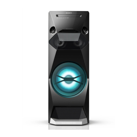
Sony SRS-ZR7 User manual

SERVICE MANUAL
Sony Video & Sound Products Inc.
SRS-ZR7
SPECIFICATIONS
PERSONAL AUDIO SYSTEM
9-896-290-04
2016I33-1
© 2016.09
US Model
Canadian Model
AEP Model
UK Model
E Model
Australian Model
Chinese Model
Ver. 1.3 2016.09
Note:
Be sure to keep your PC used for service and
checking of this unit always updated with the
latest version of your anti-virus software.
In case a virus affected unit was found during
service, contact your Service Headquarters.
亵乀恌Ⅺ
ợ䒌柵䋫
3511!.!3594/6!NI{
6261!.!6461!NI{
6836!.!6961!NI{
䪭㒬⍵廴⭨∃䋫
Ŭ!31!eCn!)FJSQ*!)3511!.!3594/6!NI{*
Ŭ!311!nX!)FJSQ*!)6261!.!6461!NI{*
Ŭ!44!eCn!)FJSQ*!)6836!.!6961!NI{*
㙤⢋∃䋫宕⬪⸊
Ŭ!21!eCn0NI{!)FJSQ*
)3511!.!3594/6!NI{*
Ŭ!21!eCn0NI{!)FJSQ*
)6261!.!6461!NI{*
Ŭ!24!eCn0NI{!)FJSQ*
)6836!.!6961!NI{*
廡柵⬝斴
31!qqn
CMVFUPPUI恌Ⅺ
ợ䒌柵䋫
3511!NI{!.!3594/6!NI{
䪭㒬⍵廴⭨∃䋫
Ŭ!31!eCn
㙤⢋∃䋫宕⬪⸊
Ŭ!31!eCn0NI{濃FJSQ濄
廡柵⬝斴
31!qqn
Dimensions (including projecting parts and
controls)
Russian model
Approx. 1.8 kg (4 lb)
Supplied accessories
AC power cord (1) (US, CND, RU, AUS, CH, HK, TW, AR, KR, TH, LA)
AC adaptor (1)
AC power cord (2) (AEP, UK, SP5)
Operating Instructions, Warranty card (US, CND)
Plug adaptor (1) (SP5, LA)
Operating Instructions (AEP, RU, UK, AUS, HK, SP5, TW, AR, KR, TH)
Warranty card (for customers in Canada) (1) (US, CND)
Warranty card (1) (AEP, UK, AUS, CH, HK, KR)
Section for USB port
USB A port ( A)
Supported format*
MP3: 32/44.1/48 kHz, 16 - 320 kbps (CBR/VBR)
AAC: 16/22.05/24/32/44.1/48 kHz, 16 – 320 kbps (CBR/
VBR)
WMA: 32/44.1/48 kHz, 16 – 320 kbps (CBR/VBR)
WAV: 16/22.05/24/32/44.1/48/88.2/96/176.4/192 kHz
(16/24 bit)
AIFF: 32/44.1/48/88.2/96/176.4/192 kHz (16/24 bit)
FLAC: 16/22.05/24/32/44.1/48/88.2/96/176.4/192 kHz
(16/24 bit)
ALAC: 16/22.05/24/32/44.1/48/88.2/96/176.4/192 kHz
(16/24 bit)
DSD (DSF/DSDIFF): 2.8/5.6 MHz (1 bit)
Transfer speed
High-speed
Supported USB device
Mass Storage Class (MSC)
USB B port ( B)
You can connect a compatible device such as a PC,
etc., to this unit using a USB cable (not supplied).
Supported format*
PCM: 44.1/48/88.2/96/176.4/192 kHz (16/24/32bit)
DSD (DSF/DSDIFF): 2.8/5.6 MHz (1 bit)
* Compatibility with all encoding/writing software, recording
devices and recording media cannot be guaranteed.
Approx. 300 mm × 93 mm × 86 mm (11 7/8in x 3 3/4in
x 3 1/2in) (w/h/d)
For customers in the UK, Ireland, Malta, Cyprus, and
Hong Kong:
Use the AC power cord (mains lead) (A).
For safety reasons, the AC power cord (mains lead) (B)
is not intended for the above countries/regions and
shall therefore not be used there.
For customers in other countries/regions:
Use the AC power cord (mains lead) (B).
(A)
(B)
T
he AC power cord (mains lead) (B) is not supplied for
customers in Hong Kong.
You can connect a USB flash drive or Walkman® that is
compatible with this unit.
Compatible iPhone/iPod models
Bluetooth technology works with iPhone 6s Plus,
iPhone 6s, iPhone 6 Plus, iPhone 6, iPhone 5s,
iPhone 5c, iPhone 5, iPhone 4s, iPod touch (6th
generation), iPod touch (5th generation).
Note
Sony cannot accept responsibility in the event that
data recorded to iPhone/iPod is lost or damaged
when using your iPhone/iPod connected to this unit.
Design and specifications are subject to change
without notice.
Условия хранения.
Товары сохраняют в упакованном виде в
темных, сухих, чистых, хорошо вентилируемых
помещениях, изолированных от мест хранения
кислот и щелочей. Температура хранения:
от -20 до +60°C. Относительная влажность
хранения: 80%. Рабочая температура: от 5°C до
35°C. Рабочая относительная влажность:
40-60%.
Mass
Power
Power requirements
DC 19.5 V (using the supplied AC adaptor connected to
AC 100 V - 240 V, 50 Hz/60 Hz power supply)
Power consumption
45 W
Power consumption (during standby mode)
Less than 0.5 W
Power consumption (during BLUETOOTH/
network standby mode)
Less than 3 W
General
(Chinese model)
(Chinese model)

SRS-ZR7
2
1. SERVICING NOTES ............................................. 3
2. DISASSEMBLY
2-1. Disassembly Flow........................................................... 9
2-2. Baffle Block .................................................................... 10
2-3. Loudspeaker (45 mm) (SP1, SP4) (Full Range) ............. 11
2-4. Loudspeaker (62 mm) (SP2, SP3) (Subwoofer) ............. 12
2-5. AMP-L Board, AMP-R Board ........................................ 13
2-6. Plate Bottom Assy........................................................... 14
2-7. MAIN Board Block-1 ..................................................... 15
2-8. MAIN Board Block-2 ..................................................... 16
2-9. MAIN Board ................................................................... 17
2-10. JACK Board.................................................................... 18
2-11. Return Spring, Bottom Lever.......................................... 19
3. TEST MODE ............................................................ 20
4. EXPLODED VIEWS
4-1. Speaker Unit Section ...................................................... 22
4-2. Plate Bottom Section ...................................................... 23
4-3. MAIN Board Section ...................................................... 24
4-4. Cabinet Block Section .................................................... 25
5. ACCESSORIES ....................................................... 26
TABLE OF CONTENTS
Notes on the AC adaptor
ŞWhen connecting or disconnecting the AC
adaptor, turn off the unit beforehand. Otherwise,
it may cause malfunction.
ŞUse only the supplied AC adaptor. To avoid
damaging the unit, do not use any other AC
adaptor.
Polarity of the plug
ŞPlug the AC adaptor into a nearby AC outlet. In
the case of a problem, unplug it from the AC
outlet immediately.
ŞDo not install the AC adaptor in a confined space,
such as a bookcase or built-in cabinet.
Laboratories. Dolby and the double-D symbol are
trademarks of Dolby Laboratories.
** For DTS patents, see http://patents.dts.com.
Manufactured under license from DTS, Inc. DTS, the
symbol & DTS and the Symbol together are
registered trademarks, and DTS 2.0 Channel is a
trademark of DTS, Inc. c DTS, Inc. All Rights
Reserved.
ŞThe BLUETOOTH® word mark and logos are
owned by the Bluetooth SIG, Inc. and any use of
such marks by Sony Corporation is under license.
Other trademarks and trade names are those of
their respective owners.
ŞGoogle Play and Android are trademarks of
Google Inc.
ŞGoogle Cast and the Google Cast Badge are
trademarks of Google Inc.
Ş“Xperia” and “Xperia Tablet” are trademarks of
Sony Mobile Communications AB.
ŞLDAC™ and LDAC logo are trademarks of Sony
Corporation.
ŞDLNA™, the DLNA Logo and DLNA CERTIFIED™
are trademarks, service marks, or certification
marks of the Digital Living Network Alliance.
ŞThis product incorporates Spotify software which
is subject to 3rd party licenses found here:
https://developer.spotify.com/esdk-third-party-
licenses/
ŞSpotify and Spotify logos are trademarks of the
Spotify Group.
ŞThe unit names and product names indicated in
this document are generally the trademarks or
registered trademarks of the manufacturer.
™ and ® marks are omitted in this document.
On copyrights
ŞThis product is protected by certain intellectual
property rights of Microsoft Corporation. Use or
distribution of such technology outside of this
product is prohibited without a license from
Microsoft or an authorized Microsoft subsidiary.
ŞiPhone and iPod touch are trademarks of Apple
Inc., registered in the U.S. and other countries.
“Made for iPod” and “Made for iPhone” mean
that an electronic accessory has been designed
to connect specifically to iPod or iPhone,
respectively, and has been certified by the
developer to meet Apple performance standards.
Apple is not responsible for the operation of this
unit or its compliance with safety and regulatory
standards. Please note that the use of this
accessory with iPod or iPhone may affect
wireless performance.
App Store is a service mark of Apple Inc.
Ş“” is a mark of the Wi-Fi Alliance.
ŞWi-Fi®, Wi-Fi Protected Access® and Wi-Fi
Alliance® are registered marks of the Wi-Fi
Alliance.
ŞWi-Fi CERTIFIED™, WPA™, WPA2™ and Wi-Fi
Protected Setup™ are marks of the Wi-Fi
Alliance.
ŞMPEG Layer-3 audio coding technology and
patents licensed from Fraunhofer IIS and
Thomson.
ŞThe N-Mark is a trademark or registered
trademark of NFC Forum, Inc. in the United States
and in other countries.
ŞThis unit incorporates High-Definition Multimedia
Interface (HDMI™) technology. The terms HDMI
and HDMI High-Definition Multimedia Interface,
and the HDMI Logo are trademarks or registered
trademarks of HDMI Licensing LLC in the United
States and other countries.
ŞThis system incorporates Dolby* Digital and the
DTS** Digital Surround System. This system
incorporates Dolby* Digital.
* Manufactured under license from Dolby
SAFETY-RELATED COMPONENT WARNING!
COMPONENTS IDENTIFIED BY MARK 0OR DOTTED LINE
WITH MARK 0ON THE SCHEMATIC DIAGRAMS AND IN
THE PARTS LIST ARE CRITICAL TO SAFE OPERATION.
REPLACE THESE COMPONENTS WITH SONY PARTS
WHOSE PART NUMBERS APPEAR AS SHOWN IN THIS
MANUAL OR IN SUPPLEMENTS PUBLISHED BY SONY.
ATTENTION AU COMPOSANT AYANT RAPPORT
À LA SÉCURITÉ!
LES COMPOSANTS IDENTIFIÉS PAR UNE MARQUE 0SUR
LES DIAGRAMMES SCHÉMATIQUES ET LA LISTE DES
PIÈCES SONT CRITIQUES POUR LA SÉCURITÉ DE FONC-
TIONNEMENT. NE REMPLACER CES COMPOSANTS QUE
PAR DES PIÈCES SONY DONT LES NUMÉROS SONT DON-
NÉS DANS CE MANUEL OU DANS LES SUPPLÉMENTS
PUBLIÉS PAR SONY.
Ver. 1.2

SRS-ZR7
3
SECTION 1
SERVICING NOTES
DESTINATION ABBREVIATIONS
The following abbreviations for model destinations are used in this
service manual.
• Abbreviations
AR : Argentina model
AUS : Australian and New Zealand models
CH : Chinese model
CND : Canadian model
HK : Hong Kong model
KR : Korean model
LA : Latin American (Except Argentina) model
RU : Russian model
SP5 : Middle East area, South East Asian area (Except Thai)
and African models
TH : Thai model
TW : Taiwan model
NOTE OF REPAIRING THE BOARDS
When the board that is installed in this unit is defective, it is re-
placed by the board. Replace the complete mounted board or the
part including the applicable board.
IMPORTANT NOTE OF REPLACING THE MAIN BOARD
When the MAIN board is replaced, be sure to perform the follow-
ing work.
1. Stick the new serial label on the bottom side of this unit.
• Sticking method of serial label
Stick the label that is enclosed in the new MAIN board so that “SE-
RIAL NO.” column and “DEVICE SERIAL No.” column of old
serial label can be seen.
Serial label
Label that is enclosed in
the new MAIN board
6WLFNLQJFRPSOHWHGILJXUH
Serial label
Label that is enclosed in
the new MAIN board
“SERIAL NO.” column and
“DEVICE SERIAL No.” column
SERIAL NO.
0000000
DEVICE SERIAL NO.
0000000
MAC1:
XX-XX-XX-XX-XX-XX
MAC2:
XX-XX-XX-XX-XX-XX
SERIAL NO.
0000000
DEVICE SERIAL NO.
0000000
MAC1:
XX-XX-XX-XX-XX-XX
MAC2:
XX-XX-XX-XX-XX-XX
MAC1:
XX-XX-XX-XX-XX-XX
MAC2:
XX-XX-XX-XX-XX-XX
–%RWWRPYLHZ–
2. Perform the connection check of network (wireless LAN/
wired LAN).
(Refer to “CHECKING METHOD OF NETWORK (WIRE-
LESS LAN/WIRED LAN) CONNECTION” on this page)
3. The MAC address and DTCP-IP ID have been changed.
Print the page 5 and page 7, cut them, and hand over them to
the customer with this unit, when returning this unit that the
repair is completed to the customer.
The SERVICING NOTES contains important information for servicing. Be sure to read this section before repairing the unit.
CHECKING METHOD OF NETWORK (WIRELESS LAN/
WIRED LAN) CONNECTION
When the MAIN board is replaced, be sure to perform the connec-
tion check of network (wireless LAN/wired LAN).
1. Checking Method of Wireless LAN Connection
Required item:
• Wireless router with the Wi-Fi Protected Setup™ (WPS) button
Procedure:
1Place the unit close to your wireless router,
and then press the Æ(power) button to turn
on the unit.
The Æ(power) indicator starts flashing. Wait
until the indicator stops flashing. It may take
about 30 seconds. Flashing Lighting
2Press and hold the UPDATE/WPS button of
the unit until it beeps (about two seconds).
3Within 90 seconds, press the Wi-Fi
Protected Setup™ (WPS) button of the
router.
Flashing Lighting
Depending on the wireless router, press and hold the Wi-Fi Protected Setup (WPS) button for a few seconds.
For details, refer to the operating instructions of your router.
When the LINK indicator lights up in orange, the Wi-Fi network connection is complete.
Checking the Wi-Fi signal strength (reception sensitivity):
The indicator of the speaker shows signal strength (reception sensitivity) by its lit status when the speaker is connected to a Wi-Fi
network and is turned on.
To receive a stronger signal
Try the following:
Change the orientation/location.
Turn off other wireless devices.
While the speaker is connected to a Wi-Fi network (the LINK indicator lights up in orange), turn on the speaker, and
then press and hold the - (volume) button and SET UP button.
The function indicators (NETWORK, BLUETOOTH, HDMI, USB-A) on the top panel start to light up.
The number of indicators lit shows the strength of the signal.
When any button is tapped, flashing stops and the signal’s strength indicator is canceled.
When no indicator is lit, the signal strength is the weakest. When four indicators are lit, the signal strength is the strongest.
1
Then, touch any button to cancel the Wi-Fi signal strength indication, repeat procedures from step
Ver. 1.3

SRS-ZR7
4
2. Checking Method of Wired LAN Connection
Procedure:
This section explains how to connect the speaker to a wireless router with a commercially-available LAN cable, then how to
connect the router to the PC.
Usually the DHCP setting is set to ON when you connect your PC to the network.
Do the following before starting.
Set the DHCP setting of your PC to ON.
Check that your PC and wireless router are turned on.
1
Connect the wireless router to the LAN port with a commercially-available LAN cable.
2
Connect the wireless router to your PC using another commercially-available LAN cable, or a Wi-Fi connection.
3
Turn the speaker on.
The (power) indicator lights up in green, then the LINK indicator begins to flash in pink. Wait about a minute until the
LINK indicator lights up in pink. When the connection is completed, the LINK indicator changes from flashing to staying lit in
pink.
Hint
4
Note
When you connect the speaker to a network for the first time after purchase, or after you initialize the speaker, the BLUETOOTH/Network
standby function is turned on automatically.
When you connect the speaker to a PC for the first time, it takes about four or five minutes until the LINK indicator stops flashing and
stays lit in pink.
COLOR VARIATIONS
(B) Black : All models
(W) White : Except US, Canadian, Russian, Taiwan models
NOTE OF REPLACING THE LOUDSPEAKER (45 mm)
The loudspeaker (45 mm) (Ref. No. SP1, SP4) has been changed
in the midway of production.
When replacing the loudspeaker (45 mm), be sure to refer to
“NOTE OF REPLACING THE LOUDSPEAKER (45 mm)” on
page 12.
SP1 – Front view – SP4
Ver. 1.3

SRS-ZR7
5
Note of the MAC address change:
The MAC address of this unit was changed along with this repair.
Please set it again if you are using the MAC address filtering function
of access point device of connection destination.
MAC address is displayed on the bottom side of this unit.
MAC1: MAC address of wired LAN
MAC2: MAC address of wireless LAN
• Please cut out along the dotted line and use it.

SRS-ZR7
6
MEMO

SRS-ZR7
7
Request of the DLNA re-setup:
The DTCP-IP ID of this unit was changed along with this repair.
When registration of client devices to the DLNA server device is not
automatic, it is necessary to register this unit into a server again.
Please refer to the Help Guide “DLNA (Digital Living Network Alli-
ance)” for the re-setup method.
• Please cut out along the dotted line and use it.

SRS-ZR7
8
MEMO

SRS-ZR7
9
SECTION 2
DISASSEMBLY
• This set can be disassembled in the order shown below.
2-1. DISASSEMBLY FLOW
SET
2-2. BAFFLE BLOCK
(Page 10)
2-7. MAIN BOARD BLOCK-1
(Page 15)
2-8. MAIN BOARD BLOCK-2
(Page 16)
2-9. MAIN BOARD
(Page 17)
2-10. JACK BOARD
(Page 18)
2-11. RETURN SPRING,
BOTTOM LEVER
(Page 19)
2-6. PLATE BOTTOM ASSY
(Page 14)
2-3. LOUDSPEAKER (45 mm)
(SP1, SP4) (FULL RANGE)
(Page 11)
2-4. LOUDSPEAKER (62 mm)
(SP2, SP3) (SUBWOOFER)
(Page 12)
2-5. AMP-L BOARD, AMP-R BOARD
(Page 13)
GRILLE FRONT SECTION
Note: Illustration of disassembly is omitted.
Please remove the grille by operating the grille front
assy detachment lever on the bottom of the unit.

SRS-ZR7
10
Note: Follow the disassembly procedure in the numerical order given.
2-2. BAFFLE BLOCK
1ten screws
(HEX 3 u10)
3sheet (B)
3sheet (B)
2Draw out the baffle block in
the direction of the arrow.
top side
front side
sheet (B)
,QVWDOODWLRQSRVLWLRQRIWKHVKHHW%
4R-ch speaker cable connector
(CN853)
5R-ch subwoofer terminal (narrow) [black]
Note 1: The terminal is locked firmly.
Please remove the terminal
carefully not to be damaged.
5R-ch subwoofer terminal (wide) [white]
Note 1: The terminal is locked firmly.
Please remove the terminal
carefully not to be damaged.
6baffle block
5L-ch subwoofer terminal (narrow) [black]
Note 1: The terminal is locked firmly.
Please remove the terminal
carefully not to be damaged.
5L-ch subwoofer terminal (wide) [white]
Note 1: The terminal is locked firmly.
Please remove the terminal
carefully not to be damaged.
4L-ch speaker cable connector
(CN804)
caulking part
speaker unit
,QVWDOODWLRQGLUHFWLRQIRUWKHVSHDNHUZLUH
Note 2: When installing the speaker wire, toward the caulking
of terminals in the direction of the speaker unit.
Insert only part way.Insert straight into
the interior.
connector
Insert at a slant.
connector connector connector
connector connector
OK NG NG
+RZWRLQVWDOOWKHFRQQHFWRU
Insert the connector straight into the interior.
There is a possibility that using this unit without
the connector correctly installed will damage it.

SRS-ZR7
11
2-3. LOUDSPEAKER (45 mm) (SP1, SP4) (FULL RANGE)
OK NG
6SHDNHUFDEOHVHWWLQJ
loudspeaker (R-ch)
(full range) (SP4) rib
speaker cable
cushion
top side
1four screws
(BTTP M2.6 u8)
2acoustic absorbent
6SHDNHUFDEOHVHWWLQJ
6SHDNHUFDEOHVHWWLQJ
,QVWDOODWLRQSRVLWLRQRI
WKHDFRXVWLFDEVRUEHQW
4three screws
(BTTP M2.6 u8)
4screw
(BTTP M2.6 u8)
rib
rib
rib
4four screws
(BTTP M2.6 u8)
Insert the acoustic absorbent
into inside of the box block.
box block (for R-ch)
7loudspeaker (45 mm)
(L-ch) (full range) (SP1)
(See Note 1, 2)
5Remove the solder.
[black]
5Remove the solder.
[blue]
5Remove the solder.
[blue]
6two speaker cables
5Remove the solder.
[black]
loudspeaker (L-ch)
(full range) (SP1)
speaker cable
7loudspeaker (45 mm) (R-ch)
(full range) (SP4)
(See Note 1, 2)
terminal
terminal
2acoustic absorbent
1four screws
(BTTP M2.6 u8)
3box block
3box block
cushion
,QVWDOODWLRQSRVLWLRQRI
WKHDFRXVWLFDEVRUEHQW
Insert the acoustic absorbent
into inside of the box block.
box block (for L-ch)
Do not touch.
right side
top side
outside
inside
inside
outside
top side
–)URQWLQQHUYLHZ–
–)URQWLQQHUYLHZ–
VSHDNHUFDEOH>EOXH@ VSHDNHUFDEOH>EOXH@
VSHDNHUFDEOH>EODFN@ VSHDNHUFDEOH>EODFN@
terminal
terminal speaker hole
speaker hole
frame
Pass the speaker wire
outside a frame.
Note 2: Do not touch the areas of the speaker
unit as figure below.
Note 1: The loudspeaker (45 mm) has been changed in the midway of production.
When replacing the loudspeaker (45 mm), be sure to refer to “NOTE OF
REPLACING THE LOUDSPEAKER (45 mm)” on page 12.
Ver. 1.2

SRS-ZR7
12
2-4. LOUDSPEAKER (62 mm) (SP2, SP3) (SUBWOOFER)
,QVWDOODWLRQGLUHFWLRQIRUWKHORXGVSHDNHUPP6363
Note 1: When installing the loudspeaker (62 mm) (SP2, SP3),
make sure that there is a position of the speaker terminal to
the position shown in the figure below.
top side
–)URQWYLHZ–
terminals position
1four screws
(BTTP M2.6 u8)
1four screws
(BTTP M2.6 u8)
2loudspeaker (62 mm) (R-ch)
(subwoofer) (SP3)
(See Note 2)
2loudspeaker (62 mm) (L-ch)
(subwoofer) (SP2)
(See Note 2)
Do not touch.
Note 2: Do not touch the areas of
the speaker unit as figure
below.
right side
top side
NOTE OF REPLACING THE LOUDSPEAKER (45 mm)
The loudspeaker (45 mm) (Ref. No. SP1, SP4) has been changed in the midway of production.
When replacing the loudspeaker (45 mm), be sure to follow the contents below and replace correctly.
Procedure:
1. Check the Part No. that has been written on the rear side of the loudspeaker (45 mm).
“1-859-171-11” or
“1-859-171-12” or
“1-859-171-13”
Xxxxxxxxxxxxxxxx
XX XX XX XX
Malaysia
– Rear view –
2. Refer to the table below, and replace according to the contents of the replacing method corresponding to the Part No. that has checked
in step 1.
Part No. Replacing method
1-859-171-11 Left and right at the same time, replace to 1-859-171-12 or 1-859-171-13.
(Be sure to use the same parts with left and right)
1-859-171-12 Replace the speaker of side that has been damaged with 1-859-171-12.
1-859-171-13 Replace the speaker of side that has been damaged with 1-859-171-13.
Ver. 1.2

SRS-ZR7
13
2-5. AMP-L BOARD, AMP-R BOARD
3DVWLQJSRVLWLRQRIWKHVKHHW%
3DVWLQJSRVLWLRQRIWKHVDUDQHWFXVKLRQ
saranet cushion
saranet cushion
flexible flat cable (FFC1) passive radiator
Insert straight into the interior.
OK
Insert at a slant.
NG
+RZWRLQVWDOOWKHIOH[LEOHIODWFDEOH
When installing the flexible flat cable, ensure that
the colored line is parallel to the connector after insertion.
colored line
flexible flat
cable
connector
colored line
flexible flat
cable
connector
Insert only part way.Insert straight into
the interior.
connector
Insert at a slant.
connector connector connector
connector connector
OK NG NG
+RZWRLQVWDOOWKHFRQQHFWRU
Insert the connector straight into the interior.
There is a possibility that using this unit without
the connector correctly installed will damage it.
2AMP-R board connector
(CN851)
9AMP-R board connector
(CN854)
hole
3AMP-L board connector
(CN802)
AMP-L
board AMP-R board
7AMP-L board connector
(CN805)
6saranet
cushion 8saranet
cushion
5AMP-L board connector
(CN801)
1two sheet (B)
sheet (B)
4Remove the flexible flat cable
(FFC1) from the hole.
This side is the terminal side.
ferrite core
ferrite core
ferrite core
The opposite side is the terminal side.
The opposite side is
the terminal side.
$(3588.+.637:.5$86
qa AMP-R board
hole
hole
hole
connection cable
(GND strap)
connection cable
(GND strap) hole
hole
boss
boss
boss
hole
q; four screws
(BTTP M2.6 u8)
qa AMP-L board
q; four screws
(BTTP M2.6 u8)
boss
boss
–/FK––5FK–
Ver. 1.3

SRS-ZR7
14
2-6. PLATE BOTTOM ASSY
front side
bottom side
3two foot
1two cushions (foot)
adhesive sheet
(plate bottom)
2two screws
(BTTP M2.6 u8)
3two foot
1two cushions (foot)
2two screws
(BTTP M2.6 u8)
2two screws
(BTTP M2.6 u8)
plate bottom assy
bracket (PWB MAIN)
chassis
Note 2: The screwdriver is inserted between the
plate bottom assy and chassis, then lift
the plate bottom assy.
Note 1: Lay a soft piece of cloth under the unit
to avoid damaging the top panel.
screwdriver
5Insert your finger in the crevice
between the plate bottom assy and the
cabinet, and while peeling off the
adhesive surface, remove the
plate bottom assy carefully.
old plate (bottom)
serial label
When replacing the plate bottom assy, peel the serial label
on the plate (bottom) carefully, and stick the serial label to
the new plate (bottom) (Refer to the figure below).
6plate bottom assy
Note 3: When removing this parts, it is not re-used to deform.
If this parts is deformed, replace it with new parts.
new plate (bottom)
1RWHRIWKHSDVWLQJRIWKHVHULDOODEHOZKHQWKHSODWH
ERWWRPDVV\ZDVUHSODFHG
4Insert two screwdrivers into
the hole, and lift the plate
bottom assy slightly.

SRS-ZR7
15
2-7. MAIN BOARD BLOCK-1
• Continued on 2-8 (page 16).
front side
bottom side
1sheet (A)
1sheet
(BOTTOM FFC)
sheet (BOTTOM FFC)
4four sheets (A)
sheet (A)
sheet (A)
2flexible flat cable
(4 pin) (CN208)
3flexible flat cable
(24 pin) (CN207)
5screw
(BTTP M2.6 u8)
5screw
(BTTP M2.6 u8)
5screw
(BTTP M2.6 u8)
5two screws
(BTTP M2.6 u8)
3DVWLQJSRVLWLRQRIWKHVKHHW$
3DVWLQJSRVLWLRQRIWKH
VKHHW$
3DVWLQJSRVLWLRQRIWKH
VKHHW%27720))&
The opposite side is
the terminal side.
connection cable
(GND strap)
connection cable (GND strap)
rib
screw hole
5three screws
(BTTP M2.6 u8)
6 Take out the coaxial
harness [gray] outward.
coaxial harness [gray]
6 Take out the coaxial
harness [black] outward.
coaxial harness [black] This side is the
terminal side.
–%RWWRPYLHZ–
right side
&RD[LDOKDUQHVV>JUD\@VHWWLQJ
rib Do not pass the wire into
the screw hole.
coaxial harness [gray]
Note: Lay a soft piece of cloth under the unit
to avoid damaging the top panel.
front side
$(3588.+.
637:.5$86
86&1'$5
7+/$&+
Ver. 1.3

SRS-ZR7
16
2-8. MAIN BOARD BLOCK-2
3flexible flat cable
(4 pin) (CN210)
2flexible flat cable
(16 pin) (CN209)
flexible flat cable
(16 pin)
4AMP-L board and
AMP-R board cable
connector (CN904)
This side is the terminal side.
5coaxial harness [gray]
(See Note 4, 5)
Push.
7coaxial harness [black]
(See Note 4, 5)
6sheet (A)
coaxial
harness
[black]
connection cable
(GND strap)
connection cable
(GND strap)
MAIN board JACK board
8MAIN board block 1Remove the MAIN
board block in the
direction of the arrow.
)OH[LEOHIODWFDEOHVHWWLQJ
Note 4: When installing the coaxial harness, insert vertically,
and push it from the top.
Note 5: When installing the MAIN board block, through the coaxial harness and connection cable (GND strap) as shown in the figure below.
Note 2: When installing the MAIN board block, dress the flexible flat cables
beforehand as shown in the figure below.
Note 3: For US and CND models, the flexible flat cable (4 pin) have been
changed from the midway of production. Refer to “Note” on page 25,
and distinguish new/former type.
coaxial harness
Insert vertically.
OK
Insert at a slant.
NG
connector
coaxial harness
connector
Insert straight into the interior.
OK
Insert at a slant.
NG
+RZWRLQVWDOOWKHIOH[LEOHIODWFDEOH
When installing the flexible flat cable, ensure that
the colored line is parallel to the connector after insertion.
colored line
flexible flat
cable
connector
colored line
flexible flat
cable
connector
Note 1: Lay a soft piece of cloth under
the unit to avoid damaging the
top panel.
flexible flat cable
(16 pin)
MAIN board
cushion (WS HOLDER)
is not stuck.
flexible flat cable
(4 pin)
flexible flat cable
(4 pin)
flexible flat
cable (4 pin)
Bend.
Bend.
coaxial
harness
[black]
coaxial
harness
[gray]
coaxial harness [gray] MAIN board block
rear side
rear side
rear side
–5HDUYLHZ–
left
side
front side
rear side rear side
coaxial harness [black]
sheet (A)
MAIN board
3DVWLQJSRVLWLRQRIWKHVKHHW$
)RUPHUW\SH86&1'
1HZW\SH86&1'2WKHUPRGHOV
cushion
(WS HOLDER)
right side
right side
Ver. 1.2

SRS-ZR7
17
2-9. MAIN BOARD
3DVWLQJSRVLWLRQRIWKHILODPHQWWDSH
3DVWLQJSRVLWLRQRIWKHFXVKLRQ:6+2/'(5
5Remove the MAIN board block
in the direction of the arrow.
1two
filament tapes
(sub material)
4six screws
(BVTT3
u5)
7cushion
(WS HOLDER)
cushion (WS HOLDER)
HDMI connector
filament tape
(sub material)
3connector
(CN401)
CN401
2connector
(CN504)
CN504
Fold to the back side.
MAIN board
6flexible flat cable
(4 pin)
(CN402
)
The opposite side is the terminal side.
front side
top side
Insert straight into the interior.
2.
Insert at a slant.
NG
+RZWRLQVWDOOWKHIOH[LEOHIODWFDEOH
When installing the flexible flat cable, ensure that
the colored line is parallel to the connector after insertion.
colored line
flexible flat
cable
connector
colored line
flexible flat
cable
connector
Insert only part way.Insert straight into
the interior.
connector
Insert at a slant.
connector connector connector
connector connector
2. NG NG
+RZWRLQVWDOOWKHFRQQHFWRU
Insert the connector straight into the interior.
There is a possibility that using this unit without
the connector correctly installed will damage it.
8MAIN board
Note 3: For US and CND models, the combination occur when
installing the MAIN board and the Cabinet block assy.
Refer to “Note 4” on page 24.
Note 2: For US and CND models, the Cushion
(WS HOLDER) have been added
from the midway of production.
Refer to “Note 4” on page 24.
Ver. 1.2
Note 1: When replacing the MAIN board, refer to “IMPORTANT
NOTE OF REPLACING THE MAIN BOARD” on page 3
and refer to “Note 4” (US and CND models only) on page 24.

SRS-ZR7
18
2-10. JACK BOARD
3DVWLQJSRVLWLRQRIWKHIRRWFXVKLRQ
1
filament tape
(sub material)
4connector
(CN905)
5flexible flat cable
(4 pin) (CN906)
3connector
(CN902)
2connector
(CN903)
3DVWLQJSRVLWLRQRIWKHILODPHQWWDSH
filament tape
(sub material)
CN906
CN905
CN902
JACK board
6screw
(BVTT3
u5)
bracket (PWB MAIN)
9foot cushion
7HIMELON 30
foot cushion guideline
JACK board
6screw
(BVTT3
u5)
–-$&.ERDUGERWWRPYLHZ–
front side
top side
This side is the terminal side.
Insert straight into the interior.
2.
Insert at a slant.
NG
+RZWRLQVWDOOWKHIOH[LEOHIODWFDEOH
When installing the flexible flat cable, ensure that
the colored line is parallel to the connector after insertion.
colored line
flexible flat
cable
connector
colored line
flexible flat
cable
connector
Insert only part way.Insert straight into
the interior.
connector
Insert at a slant.
connector connector connector
connector connector
2. NG NG
+RZWRLQVWDOOWKHFRQQHFWRU
Insert the connector straight into the interior.
There is a possibility that using this unit without
the connector correctly installed will damage it.
3DVWLQJSRVLWLRQRIWKHVKHHW86%VWDWLFRU
(0&VKHHWDQG+,0(/21
guideline
(edge of the connector)
sheet (USB static) or
EMC sheet 13 mm guideline
USB connector
HIMELON 30
–-$&.ERDUGUHDUYLHZ–
8sheet (USB static)
Note 2: For US and CND models, part has been changed to
the Sheet (USB static) from the EMC sheet, from
the midway of production.
0JACK board
Ver. 1.2
Note 1: When replacing the JACK board, refer to refer to “Note 3”
(US and CND models only) on page 24.

SRS-ZR7
19
2-11. RETURN SPRING, BOTTOM LEVER
Note: Please spread a sheet under a
unit not to injure top panel.
bottom lever
1RWHVIRUUHWXUQVSULQJLQVWDOOLQJ
Return spring is inserted fully.
OK
Return spring is floating.
1*
boss of cabinet
boss of cabinet
return spring
bottom lever
return spring
bottom side
front side
3DVWLQJSRVLWLRQRIWKHVKHHWPLFKROG
1two tapping screws
(P2 u5)
2retain plate
notch
notch
boss
4return spring
return spring
3sheet mic hold
sheet mic hold
hook
6bottom lever
boss
hole
5Draw the bottom lever
out from the hole.
front side

SRS-ZR7
20
SECTION 3
TEST MODE
Buttons and indicators position:
Top of this unit
Rear of this unit
ALL LED LIGHTS UP MODE
It can check the all LED (indicator) lights up.
Procedure:
1. Press the [ PAIRING 1] button to turn the power on.
2. Press and touch the two buttons of [STEREO PAIR] and [–]
simultaneously.
3. Touch and press the [FUNCTION] →[STEREO PAIR] →[–]
button in order (in less than 3 seconds).
4. It enters the all LED lights up mode, all LED (indicator) lights
up.
(Indicator with two colors lights up in orange, and indicator
with three colors lights up in white)
5. Each time [STEREO PAIR] button is pressed, the color of
[LINK] and [NETWORK] indicators repeatedly changes in
following order.
light up
light up
Color of [LINK]
indicator
Three-color LED One-color
LED
Red
LED
Green
LED
Blue
LED
Green
LED
White ON ON ON ON
Blue green OFF ON ON ON
Pink (Violet) ON OFF ON OFF
Blue OFF OFF ON OFF
Orange (Yellow) ON ON OFF OFF
Green OFF ON OFF ON
Red ON OFF OFF OFF
Light off OFF OFF OFF OFF
Color of [NETWORK]
indicator
Green
LED
Blue
LED
White
LED
White OFF OFF ON
Light blue ON ON OFF
Blue OFF ON OFF
Blue OFF ON OFF
Green ON OFF OFF
Green ON OFF OFF
White OFF OFF ON
Light off OFF OFF OFF
Releasing method:
Press the [ PAIRING 1] button to turn the power off.
Other manuals for SRS-ZR7
6
Table of contents
Other Sony Stereo System manuals

Sony
Sony MHC-GZR999DA User manual

Sony
Sony MEX-BT4000E User manual

Sony
Sony ZS-H10CP User manual

Sony
Sony LBT-XGV8 User manual

Sony
Sony HCD-GX750 - System Components User manual

Sony
Sony LBT-D550 User manual

Sony
Sony SRS-BTX500 Installation instructions manual

Sony
Sony LBT-XGR60 User manual

Sony
Sony MHC-RX100AV User manual

Sony
Sony HCD-CP33 User manual

Sony
Sony CMT-L7HD - Micro Hi Fi Component System User manual

Sony
Sony XDR-S100CD User manual

Sony
Sony CMT-DF1

Sony
Sony MHC-EC55 User manual

Sony
Sony HCD-D890AV User manual

Sony
Sony MEX-M70BT User manual

Sony
Sony SRS-XB3 User manual

Sony
Sony ST-SP55 User manual

Sony
Sony HCD-GNX60 User manual

Sony
Sony HCD-GR8000 User manual