66
SA-WM20
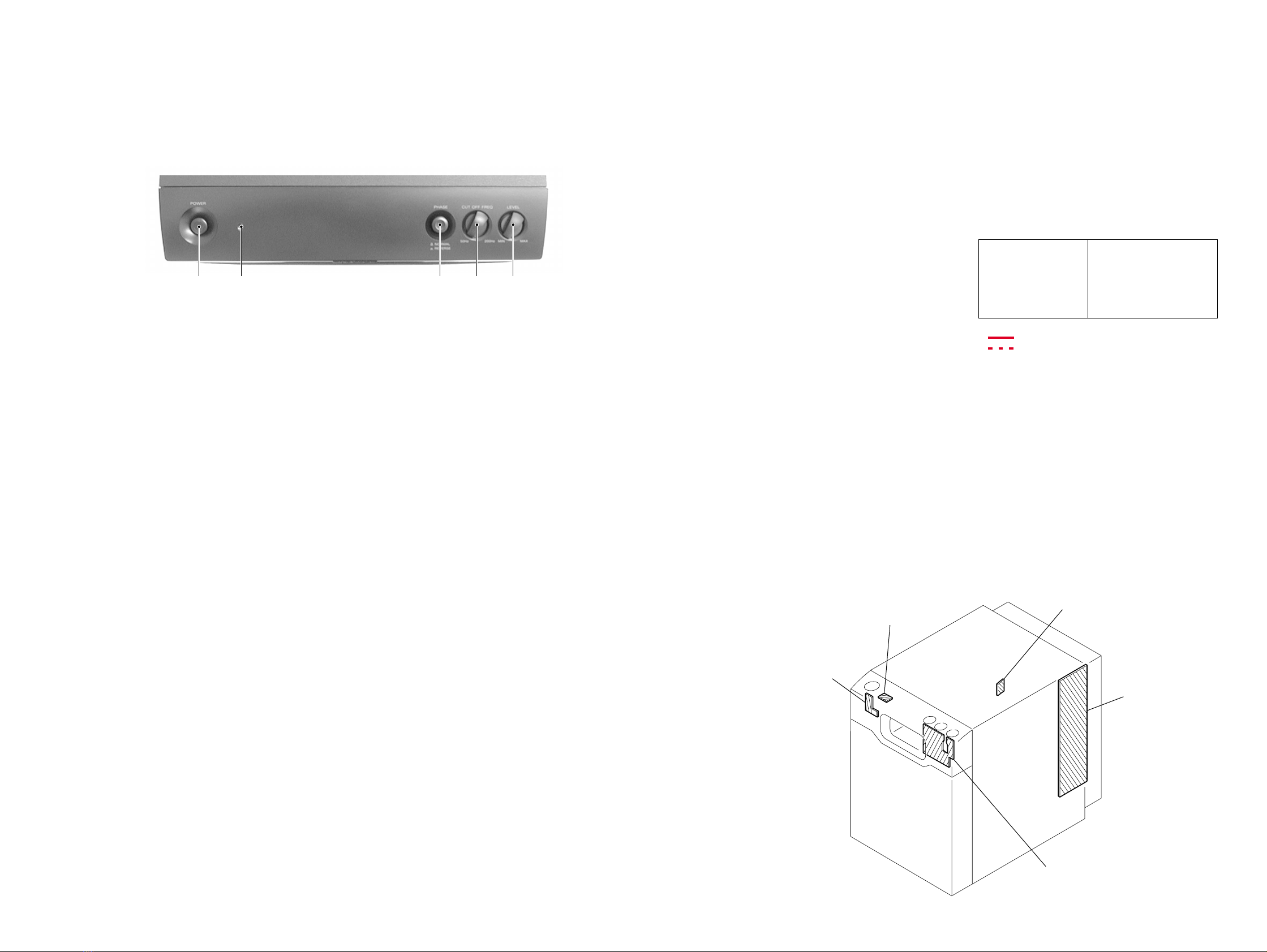
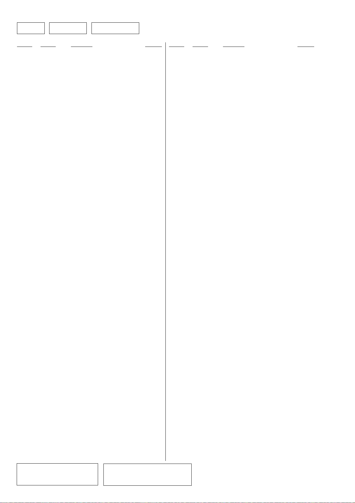
3-1. FRONT SECTION
SENTION 3
EXPLODEDVIEWS
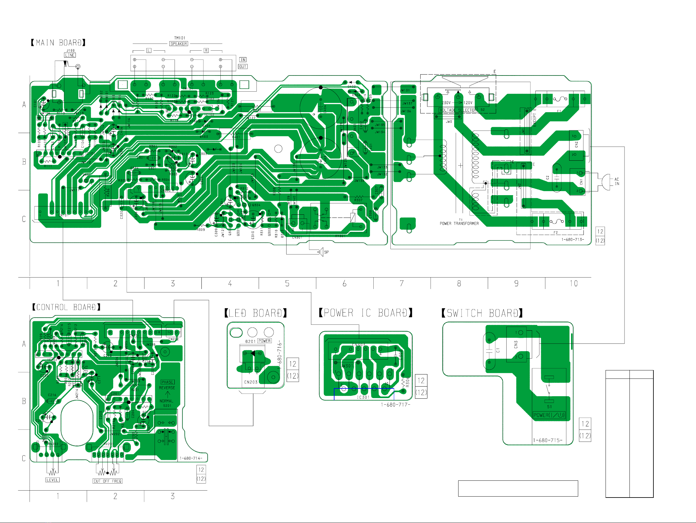
3-2. AMP SECTION
SP101
not supplied
not supplied
1
2
3
4
56
6
8
7
12
7
7
9
12 10
11
11
F1
F2
T1
not supplied
not supplied
not supplied
51
52
53
54
54
54
55
56 57
54 54
54
57
60
6057
58
59 63
61
62
The components identified by
mark 0or dotted line with mark
0are critical for safety.
Replace only with part number
specified.
• Items marked “*” are not stocked since they
are seldom required for routine service. Some
delay should be anticipated when ordering
these items.
• The mechanical parts with no reference num-
ber in the exploded views are not supplied.
• Accessories and packing materials are given
in the last of the electrical parts list.
• Abbreviation
CND : Canadian model
SP : Singapore model
MX : Mexican model
MY : Malaysia model
NOTE:
• -XX and -X mean standardized parts, so they
may have some difference from the original
one.
• Color Indication of Appearance Parts
Example:
KNOB, BALANCE (WHITE) . . . (RED)
↑↑
Parts Color Cabinet's Color
Ref. No. Part No. Description Remark Ref. No. Part No. Description Remark
1 X-4953-516-1 FRAME (BLACK) ASSY, GRILLE
(E,US,MX,CA,AEP,UK,MY,SP)
1 X-4953-686-1 FRAME (GRAY) ASSY, GRILLE (E,US,AEP,MY,SP)
2 4-232-524-01 PANEL, FRONT (SILVER)(E,US,AEP,MY,SP)
2 4-232-524-11 PANEL, FRONT (BLACK)
(E,US,MX,CA,AEP,UK,MY,SP)
3 1-680-714-12 PWB, CONTROL
4 4-232-527-01 KNOB, VOLUME (SILVER)(E,US,AEP,MY,SP)
4 4-232-527-11 KNOB, VOLUME (BLACK)
(E,US,MX,CA,AEP,UK,MY,SP)
5 4-232-531-01 PLATE, LIGHT GUIDE
6 4-973-938-81 KNOB (A), PUSH (SILVER)(E,US,AEP,MY,SP)
6 4-973-938-91 KNOB (A), PUSH (BLACK)
(E,US,MX,CA,AEP,UK,MY,SP)
7 7-685-649-79 SCREW +BVTP 3X14 TYPE2 IT-3
8 1-680-715-12 PWB, SWICH
9 1-680-716-12 PWB, LED
10 4-232-534-01 PACKING (DUCT)
11 4-914-430-11 SCREW (4X20), TAPPING
12 7-685-646-79 SCREW +BVTP 3X8 TYPE2 N-S
SP101 1-529-995-11 SPEAKER (20CM)
Ref. No. Part No. Description Remark Ref. No. Part No. Description Remark
51 1-680-713-12 PWB, MAIN
52 A-4412-797-A CABINET ASSY(SILVER) (E,US,AEP,MY,SP)
52 A-4412-798-A CABINET ASSY(BLACK)
(E,US,MX,CA,AEP,UK,MY,SP)
*53 3-703-150-11 CLAMP (E,AEP,UK,MY,SP)
54 7-685-649-79 SCREW +BVTP 3X14 TYPE2 IT-3
55 1-680-717-12 PWB, POWER IC
56 4-234-079-11 PANEL, REAR (US,MX,CA)
56 4-234-079-41 PANEL, REAR (AEP,UK,MY,SP)
56 4-234-079-51 PANEL, REAR (E)
57 4-914-518-11 SCREW (4X14), (+) (B) TAPPING
58 1-777-071-11 CORD, POWER (AEP,UK)
58 1-783-525-11 CORD, POWER (TRACKING) (E)
58 1-783-820-11 CORD, POWER (US,MX,CA,MY,SP)
*59 3-703-244-00 BUSHING (2104), CORD
60 7-685-660-19 SCREW +BVTP 4X10 TYPE2 N-S
61 3-701-946-21 LABEL, FUSE RATING
62 4-234-637-01 CUSHION (TRANSFORMER)
63 4-956-370-02 BAND, PLUG FIXED (UK)
0F1 1-532-500-31 FUSE (T630mAL/250V)(AEP,UK,MY,SP)
0F1 1-532-502-31 FUSE (T1.25AL/250V)(E)
0F1 1-532-742-11 FUSE, GLASS CYLINDRICAL(DIA.5)
(1.6A/125V)(US,MX,CA)
0F2 1-532-499-31 FUSE (T400mAL/250V)(E)
0T1 1-435-879-11 TRANSFORMER, POWER (US,MX,CA)
0T1 1-435-880-11 TRANSFORMER, POWER (AEP,UK,MY,SP)
0T1 1-435-881-11 TRANSFORMER, POWER (E)
Les composants identifiés par une
marque 0sont critiques pour la
sécurité.
Ne les remplacer que par une piéce
portant le numéro spécifié.