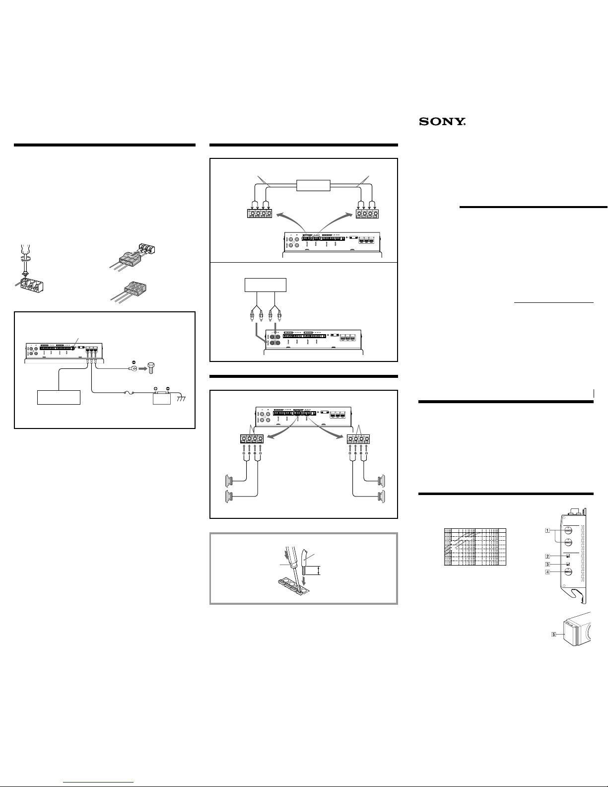
Installation
Parts list
23
ø5 ×20
×4
1
ø5 ×25
×4
Before installation
•Choose the installation location carefully so that
the unit does not interfere with driving and/or
visibility.
•Avoid installing the unit where it would be
subject to high temperatures, such as from direct
sunlight or heater exhaust, or where it would be
subject to dust, dirt, or excessive vibration.
•This unit may cause interference in the car audio
or other A/V devices. If this occurs, relocate the
unit at least 50 cm from the affected device.
•Use only the supplied mounting hardware for a
safe and secure installation.
•Consult your nearest Sony dealer for the location
of an authorized installer if you require
assistance.
Note on mounting board (not supplied)
It is recommended that a mounting board be used for safe
installation. The board should be thicker than 18 mm (3/4in.) to
accept the supplied mounting screws.
1Fasten the fittings 1securely to the unit with the screws
2.
2Fasten the unit securely to the mounting board with the
screws 3.
Precautions
•This unit is designed for negative ground 12 V
DC operation only.
•Use speakers with an impedance of 4 ohms.
•Do not connect any active speakers (with built-in
amplifiers) to the speaker terminals of the unit.
Doing so may damage the active speakers.
•Avoid installing the unit in areas subject to:
— high temperatures such as from direct
sunlight or hot air from the heater
— rain or moisture
— dust or dirt.
•If your car is parked in direct sunlight and there
is a considerable rise in temperature inside the
car, allow the unit to cool down before use.
•Be sure to install the unit horizontally so that the
air duct of the cooling fan or its fin will not be
covered with carpet etc.
•If this unit is placed too close to the car radio or
antenna, interference may occur. In this case,
relocate the amplifier away from the car radio or
antenna.
•If no power is being supplied to the master unit,
check the connections.
•This power amplifier employs a protection
circuit* to protect the transistors and speakers if
the amplifier malfunctions. Do not attempt to test
the protection circuit by covering the heat sink or
overloading the circuit.
•Do not use the unit on a weak battery as its
optimum performance depends on a good power
supply.
•For safety reasons, keep your car audio volume
moderate so that you can still hear sounds
outside your car.
Fuse Replacement
If the fuse blows, check the power connection and
replace the fuse. If the fuse blows again after
replacement, there may be an internal malfunction.
In such a case, consult your nearest Sony dealer.
Warning
When replacing the fuse, be sure to use one
matching the amperage stated above the fuse
holder. Never use a fuse with an amperage rating
exceeding the one supplied with the unit as this
could damage the unit.
*Protection circuit
This amplifier is provided with a protection circuit that
activates when a DC current is generated.
The color of the POWER/PROTECTOR indicator will change
from green to amber, and the unit will shut down.
If this happens, turn off the connected equipment, take out the
cassette tape or disc, and determine the cause of the
malfunction. If the amplifier has overheated, wait until the
unit cools down before use.
If you have any questions or problems concerning
your unit that are not covered in this manual,
please consult your nearest Sony dealer.
Troubleshooting Guide
The following checklist will assist in the correction of most problems which you may encounter with your unit.
Before going through the checklist below, refer to the connection and operating procedures.
Specifications
AUDIO POWER SPECIFICATIONS
POWER OUTPUT AND TOTAL HARMONIC DISTORTION
22 watts per channel minimum continuous average power into 4 ohms,
both channels driven from 100 Hz to 20 kHz with no more than 1% total
harmonic distortion.
Other Specifications
Speaker section
Woofer 20 cm, cone type
Impedance 6 ohm
Power amplifier section
Circuit system OTL (output transformerless)
circuit
Pulse power supply
Inputs RCA pin jacks
High level input connector
Outputs Speaker connector
Speaker impedance
4 Ω(stereo)
Maximum outputs Front/Rear outputs:
50 watts ×4 (at 4 ohms)
Subwoofer output:
120 watts ×1 (at 6 ohms)
Rated outputs (supply voltage at 14.4 V)
Front/Rear outputs:
22 watts ×4 (100 Hz – 20 kHz,
1 % THD, at 4 ohms)
Subwoofer output:
60 watts (100 Hz, 1 % THD, at
6 ohms)
Frequency response
Front/Rear outputs:
50 Hz – 50 kHz ( dB)
Harmonic distortion
Front/Rear 0.1 % or less (at
1 kHz)
Subwoofer 0.05 % or less (at
100 Hz)
Input sensitivity 0.7 V (RCA pin jacks)
8.0 V (High level input)
High-pass filter 50 – 150 Hz, –12 dB/oct
System Section
Power requirements12 V DC car battery
(negative ground)
Power supply voltage
10.5 – 16 V
Current drain at rated output: 19 A
Remote input: 1.5 mA
Dimensions Approx. 380 ×226 ×190 mm
(w/h/d) (15 ×9 ×7 1/2in.) not
incl. projecting parts and
controls
Mass Approx. 6.4 kg (14 lb.) not incl.
accessories
Supplied accessories
Mounting screws (ø5 ×20: 4,
ø5 ×25: 4), Fittings (4),
Terminal Cap
Optional accessories
Connecting cord for power
amplifier RC-46
Design and specifications are subject to change
without notice.
HI-PAS S FILT ER
FRONT
50Hz 100Hz
REAR
MODE
SUBWOOFER
INPUT
HIGHLEVEL
INPUT
SPEAKER
OUT
ACC
REMOTE
30A
POWER/
PROTECTOR
+12V
GND
50Hz 100Hz
F+ R
F
LEVEL
MIN MAX
PHASE
+
–
Dimensions
Unit: mm (in.)
×4
1
2
3
380 (15)
335 (13 1/4)
226 (9) 190 (7 1/2)
180 (7 1/8)
Problem
The POWER/PROTECTOR
indicator does not light up.
•The POWER/PROTECTOR indicator
flashes.
•The unit heats up abnormally.
Alternator noise is heard.
The subwoofer sound is too low.
Cause/Solution
The fuse is blown. nReplace the fuse with a new one.
The ground lead is not securely connected. nFasten the ground lead securely
to a metal point of the car.
The voltage going into the remote terminal is too low.
•
The connected master unit is not turned on. nTurn on the master unit.
•The system employs too many amplifiers. nUse a relay.
Check the battery voltage (10.5 – 16 V).
The remote control lead of the car audio is not connected to the remote terminal
when making a line input connection. nBe sure to connect the remote control
lead of the car audio to the remote terminal.
Use speakers with suitable impedance (4 Ω).
The speaker outputs are short-circuited. nRectify the cause of the shortcircuit.
The power connecting leads are installed too close to the RCA pin cords. n
Keep the leads away from the cords.
The ground lead is not securely connected. nFasten the ground lead securely
to a metal point of the car.
Negative speaker leads are touching the car chassis. nKeep the leads away
from the car chassis.
The level adjustment control is set to the “MIN” position.