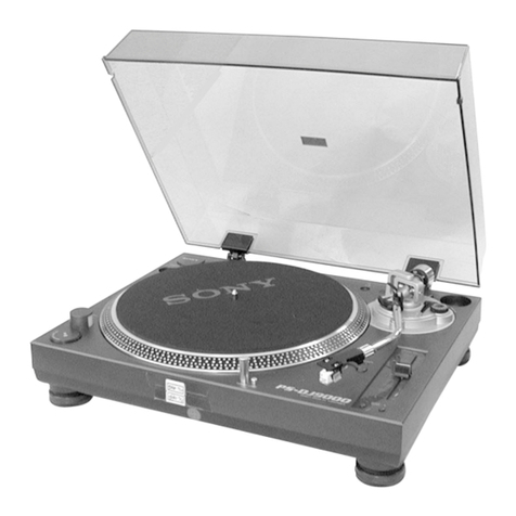
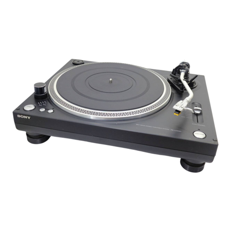
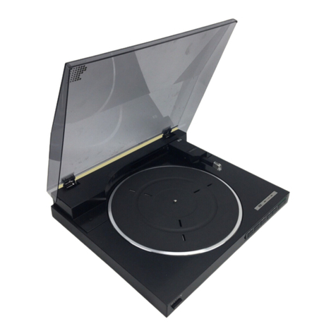
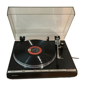
Sony PS-LX430 User manual

PS-LX430:
US
Model
PS-LX430C:
US
Model
Canadian
Model
PS-LX431:
AEP
Model
UK
Model
E
Model
PS-LX431N:
US
Model
PS-LX433:
US
Model
SPECIFICATIONS
Turntable
Platter
30.0
cm(12
in.),
aluminum-alloy
diecast
Motor
DC
servo
motor
Drive
system
Belt
drive
Controlsystem
DCservocontrol
system
Speed
33!/3
rom,
45
rom
Start-up
time
Comes
to
nominal
speed
within
4/2
rotation
(33/3
rpm)
Wow
and
flutter
0.045%
(WRMS)
Signal-to-noise
ratio
70
dB
(DIN-B)
Automatic
system
Lead-in,
return,
reject,
repeat,
record
size
selection
Suspension
system
High
elasticity
gel
insulator
Toneam
PS-LX430/430C/433:
Type
Statically
balanced
Pivot-to-stylus
length
216.5
mm
(81/2
in.)
Usable
cartridge
Plug-in
type,
6g
Sony
VL-45G
Trackingerror
+3,
—-1
PS-LX431/431N:
Type
Dynamically
balanced
Pivot-to-stylus
length
216.5
mm
(81/,
in.)
Overhang
16.5
mm
(22/39
in.)
Tracking
error
+3,
—-1
SAFETY-RELATED
COMPONENT
WARNING!!
COMPONENTS
IDENTIFIED
BY
SHADING
AND
MARK
A
ON
THE
SCHEMATIC
DIAGRAMS
AND
IN
THE
PARTS
LIST
ARE
CRITICAL
TO
SAFE
OPERATION.
REPLACE
THESE
COMPONENTS
WITH
SONY
PARTS
WHOSE
PART
NUMBERS
APPEAR
AS
SHOWN
IN
THIS
MANUAL
OR
IN
SUPPLEMENTS
PUBLISHED
BY
SONY.
Cartridge
PS-LX430C:
VL-45G
Type
Moving
magnet
type
Frequency
response
20
Hz
to
20
kHz
Channel
separation
20dB
at
1
KHz
Output
voltage
3.5mVat1kHz,5cm/sec.
Loadimpedance
50to
100
kilohms
Tracking
force
1.259
Stylus
Sony
ND-145G
(conical
0.6
mil
diamond)
Weight
6g
PS-LX430/LX433
Not
supplied
PS-LX431:
VL-42G
Type
Moving
magnet
type
Frequency
response
20
Hz
tO
20
kHz
Channel
separation
16dB
at
1
kHz
Output
voltage
2.5
mV
at
1
kHz,
5
cm/sec.
Loadimpedance
=
50to0
100
kilohms
Tracking
force
2g
Stylus
Sony
ND-142G
(conical
0.6
mil
diamond)
Weight
8g
~
Continued
on
page
2
—
ATTENTION
AU
COMPOSANT
AYANT
RAPPORT
A
LA
SECURITE!
LES
COMPOSANTS
IDENTIFIES
PAR
UNE
TRAME
ET
UNE
MARQUE
A
SUR
LES
DIAGRAMMES
SCHE-
MATIQUES
ET
LA
LISTE
DES
PIECES
SONT
CRITIQUES
POUR
LA
SECURITE
DE
FONCTIONNEMENT.
NE
REM-
PLACER
CES
COMPOSANTS
QUE
PAR
DES
PIECES
SONY
DONT
LES
NUMEROS
SONT
DONNES
DANS
CE
MANUEL
OU
DANS
LES
SUPPLEMENTS
PUBLIES
PAR
SONY.
STEREO
TURNTABLE
SYSTEM
SONY.

PS-LX430/430C€/431/431N/433
General
Power
requirements
Power
consumption
Dimensions
Weight
US,
Canadian
model:
120
V
ac,
60
Hz
AEP
model:
220
V
ac,
50/60
Hz
UK
model:
240
V
ac,
50/60
Hz
7W
PS-LX430/430C/431/433:
Approx.
430
x
100
x
360mm
(w/h/d)
(17x
4x
14%
inches)
incl.
projecting
parts
and
controls
PS-LX431N:
Approx.
430
x
110
x
360
mm
(w/h/d)
(17x
4%
x
14
in.)
including
projecting
parts
and
controls
PS-LX430/430C/431/433:
Approx.
3.5
kg
(7
Ibs
12
oz),
net
Approx.
4.5
kg
(9
Ibs
10
oz),
in
shipping
carton
PS-LX431N:
Approx.
2.9
kg
(6
Ib
7
oz)
net
MODEL
IDENTIFICATION
—
Specification
Label
—
PS-LX430,
PS-LX430C,
PS-LX433
SONY.
MODEL
NO,
PS-Lx430
i
STEREO
TURNTABLE
SYSTEM
LLM
SERIAL
NO.
MADE
IN
JAPAN
US,
Canadian
model:
AC:
120V
—60
Hz
7W
365
mm
(14
3s
in.)
a
385
mm
(15
3/32
in.)
(PS-LX431N:
Dust
cover
is
not
supplied)
PS-LX431,
PS-LX431N
SONY.
wove.
no,
psixess
et
ee
eee
a}
STEREO
TURNTABLE
SYSTEM
MLL
SERIAL
NO.
MADE
IN
JAPAN
US
model:
AC:
120V
—60Hz
7W
AEP,
UK
model:
AC:
220V
—
50/60
Hz
7W
E
model:
AC:
110
—220V,
220
—240V
50/60
Hz
7W,

SAFETY
CHECK-OUT
(US
Model)
After
correcting
the
original
service
problem,
perform
the
following
safety
check
before
releasing
the
set
to
the
customer:
Check
the
antenna
terminals,
metal
trim,
‘“‘metallized”’
knobs,
screws,
and
all
other
exposed
metal
parts
for
AC
leakage.
Check
leakage
as
described
below.
LEAKAGE
TEST
The
AC
leakage
from
any
exposed
metal
part
to
earth
ground
and
from
all
exposed
metal
parts
to
any
exposed
metal
part
having
a
return
to
chassis,
must
not
exceed
0.5mA
(500
microampers).
Leakage
current
can
be
measured
by
any
one
of.
three
methods.
1.
A
commercial
leakage
tester,
such
as
the
Simpson
229
or
RCA
WT-540A.
Follow
the
manufacturers’
instructions
to
use
these
instru-
ments.
2.
A
battery-operated
AC
milliammeter.
The
Data
Precision
245
digital
multimeter
is
suitable
for
this
job.
3.
Measuring
the
voltage
drop
across
a
resistor
by
means
of
a
VOM
or
battery-operated
AC
volt-
meter.
The
“limit”
indication
is
0.75
V,
so
analog
meters
must
have
an
accurate
low-
voltage
scale.
The
Simpson
250
and
Sanwa
SH-63Trd
are
examples
of
a
passive
VOM
that
is
suitable.
Nearly
all
battery
operated
digital
multimeters
that
have
a
2V
AC
range
are
suitable.
(See
Fig.
A)
To
Exposed
Metal
Parts
on
Set
AC
0.15
uF
vo/tmeter
;
(0.75
V)
—=
~~
Earth
Ground
Using
an
AC
voltmeter
to
check
AC
leakage.
PS-LX430/430€/431/431N/433
CAUTION
ON
INSTALLING
BELT
When
installing
beit,
glossy
should
be
faced
outside.
Motor
pulley
Glossy
side

PS-LX430/430C/431/431N/433
|
SECTION
1
OUTLINE
1-1.
PARTS
IDENTIFICATION
PS-431
PS-LX431N
©
©
O
@
@
45-rpm
adaptor
©
Auto-record-size
selection
holes
and
lamp
©
Disc
centering
guides
@
Drop
point
adjustment
hole
@
Tonearm
|
©
Arm
rest
©
Cartridge
(not
supplied
with
US,
Canadian
certain
models
of
PS-LX430/LX433)
©
Sub-weight
PS-LX430
PS-LX430C
PS-LX433
9
I
©
ANTI-SKATING
compensator
Normally,
set
it
at
the
center
position.
If
the
stylus
is
driven
inward
when
the
tone
arm
is
lowered
to
the
lead-
in
groove,
turn
the
ANTI-SKATING
compensator
to
@.
If
the
stylus
is
driven
outward,
turn
the
ANTI-SKATING
compensator
to
©.
oe
Center
position

PS-LX430/430C€/431/431N/433
@
vw/V¥
(cueing)
lever
Used
to
fift
or
lower
the
tonearm.
@
START/STOP
button
@®
REPEAT
button
and
indicator
®
SPEED
selector
and
indicators
Set
the
SPEED
selector
according
to
the
speed
of
the
record
to
be
played.
For
45-rpm
records,
depress
the
selector
when
a
45
rpm
record
is
to
be
played.
For
a
33%/s
@®
SYNC
connector
records,
press
it
again.
Connect
to
the
SYNC
connector
of
the
optional
Sony
tape
deck
equipped
with
a
3-pin
flat
connector.
@
Rubber
mat
@®
CONTROL
S
IN
connector
®
Turntable
platter
Connect
to
the
CONTROL
S
OUT
or
REMOTE
OUT
connector
of
an
optional
Sony
system
control
tuner
or
@
Center
spindie
receiver
for
whole
audio
system
remote
control.
@
POWER
switch
@
CONTROL
S
OUT
connector
Connect
to
the
CONTROL
S
IN
or
f
REMOTE
OUT
con-
nector
of
Sony
audio
equipment
equipped
with
a
4-pin
remote
control
connector
for
remote
control
operation.
1-2.
BLOCK
DIAGRAM
B+
;
(12V)
et
(12V)
33/45
SWITCH
RVIO!
2°
33rpm
SPEED
Q105,107
ADJ
Mi0!
(TURNTABLE
MOTOR
1cid2
SYSTEM
CONTROL
RVIO2
45rpm
SPEED
ADJ
i
(@)
&
CNP
2
OFF
S601
°
BEST
ARM
REST
oe
@?)ARM
REST
oy
COTROL
S
OUT
MOTSWITCH
G)
MOTOR
DRIVE
fo)
O
OFF
_
0106
C101
O
28)
PLAY
$701
PLAY
oN
CNP
3
=
SWTCHING
COTROL
S$
IN
S102
ART/STOP
SIR
HAPER
O
O
@3)START/STO
IRCS@2)
SHAPE
Pr
,
$103
—
REPEAT
REPEAT
REPEAT
°
@)
$104
GEPEED
PAUSE
RELEASE(O)
eo
oO]
_cNP4
45
SPEED
33
SYNC
O
a3
At'
REC.
MUTE
(9)
a
(8)45LED
PT
POWER
TRANSFOR
MER
Ay
Dil2
33LED
©
©
RECT
4
.
DIOI-104
DIN
'
(6)REPEAT
LED
REPEAT
OFF
SIO}
al
pee
PMI02
SIZE
PM)
SOLENOID
DRIVE
X
M10.
SOLENOID
‘
.
~
Q30!
D108
——
PMO
SIZE
OET
Oloa
size
STAR
OOD
soEN
Os
x
START
/STOP
i7em
SOLENOID
(5)
.
©)
aor
*
SIZE
DET
|
30cm
Xi

PS-LX430/430C/431/431N/433
|
section
2
DISASSEMBLY
2-1.
REMOVAL
@
Follow
the
disassembly
procedure
in
the
numerical
order
given.
TURNTABLE
MOTOR
(M101)
@
motor
screw
'S)
oS
>|,
BRACKET
(8),
MOTOR
Ge
:
l
Remove
bottom
plate.
(PTPWH
3
x
12
9
pcs)
§
@
turntable
motor
(M101)
S/S
SW
BOARD
LAMP
BOARD
@
t
G0
PTPWH3
x
10
As>
{
chassis
bracket
@
PTPWH3
x
10
®
lamp
board
S/S
bottom

|
PS-LX430/430C/431/431N/433
SYSTEM
CONTROL
(A)
BOARD
@
«QO
PTPWH3
x
10
O
prewH3
x
-)
i
System
control
(A)
board
4
b
ie
SYSTEM
CONTROL
(B)
BOARD

PS-LX430/430C/431/431N/433__
2-2.
INSTALLATION
PUSH
ROD,
LIFTER
LEVER
e-°
PTPWH3
x
10
@
lifter
retainer
(C)
ae
—
@
PTPWH3
x
10
special
washer
(12
dia)
4)
lifter
lever
ass’y
lifter
retainer
(C)
Sony
grease
(SGL-501)
Hf}
i
Q
lifter
cam
Sony
grease
(SGL-501)
Sony
grease
(SGL-501)
Caution
for
installation:
When
the
push
rod
is
replaced,
apply
silicon
oil
(viscosity:
500,000
cs)
to
the
push
rod
as
illustra-
ted
below.
Caution:
When
lubricating,
rotate
and
move
the
push
rod
up
and
down
a
few
times.
lifter
guide
set-screw
HEX.
2.6
x
8
Do
not
hurt
the
surface
of
this
area.
oil-retaining
groove
|,
(silicon
oil
viscosity
push
rod
case
a
500,000)
Parallel
lifter
lever
(C)
Sony
grease
(SGL-501)
—_o
shaft
Sony
grease
(SGL-501)
lifter
lever
(A)
B2.6
x
16
contact
cement

TONEARM
UNIT
CHASSIS
BLOCK
chassis
block
|
PS-LX430/430C/431/431N/433
tonearm
unit
PTPWH3
x
10
PS-LX430/430€/431/431N/433
INDEX
LEVER
(C)
@cE9
Sony
grease
(SGL-501)
@
index
lever
(C)
aN
main
lever
PT
\
Sony
grease
Xe
L-501)
«\
INDEX
LEVER
(B)
@
Set
the
click
lever
in
the
direction
of
the
arrow.
QcE
at
click
lever
@
poly-slider
\.
(9.5
dia.)
ely
@
index
lever
(B)
ass’y
Rotate
the
index
lever
(C)
in
the
direction
of
the
arrow.
index
lever
(C)
Sony
grease
(SGL-501)
main
lever
index
lever
(C)
Rotate
the
index
lever
(C)
on
the
direction
of
the
arrow
@
and
put
the
stud
(6)
of
the
index
lever
(B)
into
the
click
lever.
On,
.
=
a—
Click
lever
index
lever
(B)

PS-LX430/430C€/431/431N/433
PS-LX430/430€/431/431N/433
ARM
LEVER
3)
Set
the
position
of
boss
and
hole
(A).
Sony
grease
hole
(A)
(SGL-501)
hole
(A)
@
arm
lever
1)
Set
the
click
lever
in
the
direction
of
the
@
double
cup
set
screw
3x
8
click
lever
IFC
(ANTI-SKATING)
KNOB
5)
Install
the
spring
on
the
IFC
cam.
@
PTP3
x
25
@
plain
washer
14
IFC
spring
Sony
grease
(SGL-501)
stopper
boss
8]
Hook
the
long
side
of
spring
in
the
stopper
boss.
the
frame.
@
Install
washer
(N)
+r
Q——
washer
(N)
on
the
IFC
knob.
|
y
Sony
grease
|
ea
(SGL-501)
rT
ney
IFC
knob
aA
@
Fully
turn
the
IFC
knob.
|
-
9?
Insert
the
IFC
knob
in
PHONO
BOARD
@
PTPWH3
x
10
a
Ja
|
shield
plate
(lower)
white
Af
—
ae
ee
phono
board
ASE
A
~!
iS
LPO
|
Sei
hig!
ge
E
DRIVE
GEAR
EP
iepa
sll
grease
@
drive
gear
ca
tA
CORA
!
Set
the
main
lever
in
the
direction
of
the
arrow
as
illustrated.
a
tena
{ya
main
lever
fA
Sony
grease
ay
(SGL-501)
{
|
Sony
grease
(SGL-507)
kK)
/nstall
the
drive
gear
pulling
the
reset
lever
in
the
direction
reset
lever
of
the
arrow
as
illustrated.
Sony
grease
(SGL-501)

PS-LX430/430C€/431/431N/433
TONEARM
(PS-LX431)
1.
LEAD
WIRE
INSTALLATION
Pass
piano
wire
with
lead
wires
through
pipe
as
shown
in
Fig.
A.
Pass
piano
wire
with
lead
wires
through
center
joint
assy
as
shown
in
Fig.
B.
\
piano
wire
lead wire
Kl
piano
wire
—_——_+»
joint
assy,
center
2.
ARM
PIPE
REMOVAL
Ss)
(2)
joint,
center
3)
shaft
assy,
rotary
0
pin,
horizontal
©
pipe,
arm
@
P2x5

PS-LX430/430€/431/431N/433
TONEARM
(PS-LX430,
433)
1.
LEAD
WIRE
INSTALLATION
1-1.
Pass
piano
wire
with
lead
wires
through
pipe
as
shown
in
Fig.
A.
(-
1-2.
Pass
piano
wire
with
lead
wires
through
center
joint
assy
as
shown
in
Fig.
B.
\
Piano
wire
Fig.
A.
rt
lead
wire
Piano
wire
——»
(+
joint
assy,
center
Fig.
B
2.
ARM
PIPE
REMOVAL
@
joint
assy,
center
©
pipe,
arm
SL
\
8
BO
0
wenn
a
Gj
@
sheet
(S)
Qe
@
screw,
pivot
@
nut
(A),
lock,
pivot
lead
wire

PS-LX430/430C€/431/431N/433
SECTION
3
3-1.
MECHANICAL
ADJUSTMENTS
ADJUSTMENTS
Longitudinal
Sensitivity
Adjustment
(PS-LX430/430C/433)
1.
Install
the
cartridge
and
slide
the
sub
weight
at
sy
CO
side.
.
Place
a
weight
of
about
5g
on
the
pipe
joint.
.
Adjust
the
weight
position
so
that
the
arm
is
a
balanced.
pivot
screw
Pivot
screw
.
Place
a
weight
of
about
150mg
on
the
cartridge
lock
nut
(right
over
the
stylus).
.
Adjust
the
pivot
screw
so
that
the
stylus
tip
goes
down
5mm
or
more.
Note:
If
the
pivot
screw
is
secured
excessively,
the
pivot
sub
weight
bearing
may
be
damaged.
weight
(150mg)
sub
weight
weight
(5g)
More
than
5
5mm
(%
“)
tT
Stylus
Force
Adjustment
(PS-LX431)
1.
Turn
the
adjustment
screw
to
obtain
zero
balance.
2.
Turn
the
adjustment
screw
again
so
that
the
stylus
force
becomes
2g
on
the
stylus
force
gauge.
adjustment
screw
‘ey
lighter
heavier
Shell’s
Horizontal
Balance
Adjustment
Loosen
the
neck
cylinder
screw
and
adjust
so
that
section
@)
(shell
slant)
is
less
than
0.5mm.
@)
Jess
than
0.5mm
screw
PTP2x5

PS-LX430/430€/431/431N/433
Brake
Lever
Position
Adjustment
1.
Rotate
the
drive
gear
in
the
direction
of
the
arrow
by
hand,
and
set
the
reset
lever
for
reset
position
(show
the
Fig.
1).
Then,
confirm
that
the
size
lever
is
contact
with
chassis
lightly
(shown
in
the
Fig.
2,
®
).
2.
Adjust
the
adjustment
screw
so
that
a
gap
becomes
in
0.3
0.2mm
(shown
in
the
Fig.
3).
drive
gear
3.
After
the
adjustment,
lock
the
adjustment
screw
with
locking
compound.
reset
lever
brake
lever
0.3£0.2mm
4
size
lever
brake
lever
Fig.
3
rectangular
hole
size
lever
size
lever
adjustment
screw
reset
lever

PS-LX430/430€/431/431N/433
Stylus
Height
Adjustment
Note:
Perform
both
adjustment
for
manual
and
automatic
operations.
1.
Automatic
1)
Put
a
test
record
on
the
mat.
2)
Depress
the
lifter
lever
to
make
a
lifterdown
mode.
3)
Move
the
tonearm
to
out
of
groove
at
record
by
hand.
4)
Rotate
the
turntable
by
hand
and
at
make
tonearm
lead-in.
5)
Move
the
tonearm
to
out
of
groove
of
record
by
hand
again.
6)
Rotate
the
turntable
by
hand
and
make
the
tonearm.
7)
Then,
loosen
the
adjustment
screw
(A)
and
adjust
the
height
of
the
tonearm
lifter
so
that
the
stylus
height
becomes
in
4
—
8mm.
8)
Rotate
the
turntable
by
hand
slowly
and
move
the
tonearm
to
the
most
outer
groove
of
record.
9)
Confirm
that
stylus
height
becomes
in
4—8mm.
2.
Manual
1)
Put
a
test
record
on
the
mat.
2)
Move
the
tonearm
to
out
of
groove
of
record
by
hand.
3)
Rotate
the
turntable
by
hand
and
make
the
tonearm
lead-in.
4)
Raise
the
lifter
lever
to
make
a
lifter-up
mode.
5)
Move
the
tonearm
until
most
outer
groove
of
record
by
hand.
6)
Adjust
the
adjustment
screw
(B)
so
that
the
stylus
height
becomes
in
4—8mm.
7)
Move
the
tonearm
to
the
out
of
groove
of
record
by
hand.
Confirm
that
stylus
height
becomes
in
4—8mm.
8)
Rotate
the
turntable
by
hand
and
return
the
tonearm
to
arm
rest.
9)
After
the
adjustment,
lock
the
portion
@
with
suitable
locking
compound.
Note:
@
Stylus
height
difference
should
be
within
2mm,
between
automatic
and
manual
operation.
When
the
arm
returns.
®
The
tonearm
should
be
not
contact
with
the
top
part
of
the
rest
when
the
tonearm
returns.
—17-
adjustment
screw
(A)
adjustment
screw
(B)

PS-LX430/430€/431/431N/433
3-2.
ELECTRICAL
ADJUSTMENT
Stylus
Drop-point
Adjustment
Speed
Adjustment
Note:
Stylus
force
adjustment
should
be
completed.
1.
Put
a
test
record
YFSC-16
on
the
mat.
2.
Set
the
SPEED
switch
to
33%
3.
Press
the
START/STOP
button.
Note:
Be
sure
to
perform
45rpm
adjustment
before
33rpm.
1.
Put
a
stroboscope
board
on
the
mat.
2.
Set
the
SPEED
switch
to
45.
Press
the
START/STOP
button.
Adjust
RV102
so
that
the
stripped
pattern
stroboscope
board
is
stationary.
Set
the
SPEED
switch
to
33.
Adjust
RV101
in
the
same
way.
4.
By
using
a
screwdriver,
turn
the
adjustment
screw
so
that
the
stylus
tip
drops
on
the
record
at
the
4—16
counts
position.
Note:
The
proper
adjustment
for
a
30cm
record
is
also
correct
for
a
17cm
record.
to
inner-groove
to
out-of-groove
{count
increases)
(count
decreases)
adjustment
screw
RV102
(45
rpm)

SECTION
4
DIAGRAMS
PS-LX430/430€/431/431N/433
|
PS-LX430/430€/431/431N/433
1
2
Oe
be
Me
Nn
Ot Oe
OO,
a
so
1
15
16
17
18
19
4-1.
MOUNTING
DIAGRAM
-—
Cenductor
Side
—
@
Semiconductor
Lead
Layouts
TRANSFORMER
:
is
A1GE-557
2SA733
:
mT
wa
,
:
.
LM6416E-55
peach
Aa
mj
=
vo
[SYSTEM
CONTROL
(B)
BOARD]
|
ee
ca
LAMP
BOARD]
|
:
7
“
one
&
(SIZE
(OUT)
BOARD]
[
Vs
!
cathode
i
Deni
i
P
|
a
-==———
(GND)
PLIOI
H
;
silat
BOARD]
!
i
4
(SIZE)
|
;
(Top
view!
|
AC
i
}
IN
}
vie
anode
'
Cl]
oupc1470H
L
ak
et,
|
2SD809
1$$202-1
[4]
:
eens
|
letter
side
a
(SIZE
(IN)
BOARD)
age.
SPONERBOANOT:
=
re
cathode
TRANSFORMER
|
WW
|
Xf
ite
1234
|
(MECHA)
.
—E
CB
|
:
CHASSIS,
RE
Size
GET
8
}
i
*
~
“ws
(|
AC
IN
!
i
:
eer
:
|
“a
|
iataks
Lo
ee
Eve
ee)
ss
ah
URNA
Oa
a
i
:
|
2SB808
DTC114EF
PS-LX430(0)
sen
NA.
oy
omnsessrum
wh
|
|
:
jek
!
|
<
Ee
Sk
ee
J
2PULSES/
TURN
ay
DTC114ES
GL-5HD21
~~
|
sg
yp
a
SRY
{
AEP
/
|
Ei
ss
y
|
wertour
recone
—
ALLA.
on
sous
sesytuen
|
MODEL
—
|
2}
&
>
RED
{
UK
MODEL
|
a
|
;
ie
vi=456)
|
E
.
\
:
Fan
oye
Ba
C
E
\
/
\
|
&
cathode
VA
NA
Lk
wo
sy
anode
2
E
a
M01
TURNTABLE
®
MOTOR
ONR-7600A
orrow
mork
RED
BLK
PMi02
SIZE
SOLENOID
START
STOP
eoweR
SOLENOID
TRANSFORMER
Note:
@
Color
code
of
sleeving
over
the
end
of
the
jacket.
{S/S
SW
BOARD]
WHT
Slo2
2
pi
Ye"
“Seececof
HO
L
‘
S101
POWER
(REOMGR
sal
©
O-——:
parts
extracted
from
the
component
side.
290
|
es
ee
yy
ae

|
PS-LX430/430C/431/431N/433
_
PS-LX430/430C/431/431N/433
1
2
3
4
5
6
7
8
9
10
11
12
13
14
15
4-2.
SCHEMATIC
DIAGRAM
!
|
Cll
Lf
fe)
1000
icio2
:
~~
“DnO
Ql05
{SYSTEM
CONTROL
(A)
BOARD]
p
mie
EF
LM6416E-557
1S$202-|
258808
{PHONO
BOARD)
swheHn
G,
SHAPER
SYSTEM
CONTROL
33/45SWITCH
DIIS
.
lav
nnemnnd
)
WHT
Q107
RI2i
'33rpm
|
L-
CH
DTCII4ES
1
SR
[es
|
7
33/45
SWITCH
33rpm:
9V
i
~
C108
f°)
aie
45rpm:
7.5V
|
ay
R-CH
|
10k
33e0mn:6
Y
R122
ols
ie
on
MIOl
sige
asad
a
at
te
et
tah
sy
DIS
Cll?
pforpm:
OV
Rviog
TURNTABLE
MOTOR
eT
Oe
es
me
Mi
2
Cr)
33pm:
ay
th
DNR
~
76004
$50!
papenany
|
1§$202-
1000p,
“ss
oe
Vpn
:
7.3V
BS
Etec
AGE
Re
|
Ri40
33rpm:0V
33rpm:
7V
Pa
i
\
22k
pfotpm
3V
45cm:
6.8Y
RH
|~
(Cll
DINO
Cl09
470
|
45rpm
R
Q107
Orev
|
SPEE
|
L
JUPCI470H
fee
<>
oj
RI3]
LRI3O
4
RI34
a
6Y
pasa
e
:
33th
8.4
a
eee
;
|
cxereibee
OFF
oj
lok
10k
*
10k
a
RM
REST
MODE:
OV
(2g
BBY
4G
Marpm:
8.8
$60)
O
{
|
ARM
REST
aE
|
|
OFF
ale?
pPLay
Suite
ON:0V
i
s701
KS
8)
PLAY
PLAY
OON
jo
IC102
-
6Y
7S
SW
BOARD
WHEN
PUSHING
[S
SOARD
ass
|
Sloe
ow
ov 1"
(SYSTEM
CONTROL
BOARD]
STARTSTOP
—S
o—
eon
START/STOP
oe
eel
RIS3
a
r
WHEN
PUSHING
ov
ie
$103
a)
_——
3
ON:
OV
ed
i
Sem
I
52]
cNP4
REPEAT
Oo
0°
PAUSE
Ov
ne
O°}
[SYNC
$104
a
PB
—
BEDE
Hes
START
ARH
Dov
qos
0
.@)
©
26)
rhs
ealh
def
asthe
(eee
tam.
3
SV
se
45
33
Fhe
pon
re
rg
SPEED
cid
cis
secn2
cue
Lis
104
ON
_
RI52
|
|
|
Q109,
110
i
pT
Tower.
0.01
TOO!
TOO!
“T
O0l
7
O0t
WHEN
PUSHING
10k
ee
ee
DICII4ES
Oa|
CNP
3
"an
POWER
S104
ON:
OV
WV
[Sse
'
SWITCHING
re)
_TRansronwen
AN
ABOARD
{
+
ON:
OY
e
|
fv
CONTROL
S
IN]
.
4
i
DIN
ptl2
DIZ
tm
i
REC.
MUTE
(9-4
STC
bss
QO
O
laruiag
ole
6
eee
ae
ti!
is
"
;
aera]
[3]
an
;
ee
|
33rpim:
O.18y
|
S3rpm
4.2
j
|
R143
i
(¥)
(¥)
(¥)
a5rpm:
4,2y
|
45rpm:0,18V
;
ouie
|
anne
OY
100
°,
or
|
oe
be
h0.450c
nee
°3
|
[CONTROL
$
OUT
i
=
O
D106
3
Li
»
12V
r
a
De
7
“AEP,
UK
MODEL
sheng
REPEAT
LED
ON:0.18
TUS
wit
LIGHT:
0.6¥
OV
DIO!
-
104
_GL-SHD2I
WITHOUT
LIGHT
:5.2V
7
NO
OH.
L
R108
lOE2
ee
cena
chee
[SIZE(OUT)
BOARD]
i
int
i”
TPOWERY,
!
i
:
POWER
a
Ay
ABOARD
B
&
t
on
:
&
ON
V
i
Q301
Ck
Q301
CV)
i
.
“SOLENOID
'
CANADIAN,
AEP,UK,
&
|
PD40l
SOLENOID
SOLENOID
ane
a
(
SIZEDET
17cm
RIO9
|
is
MODEL
=
47k
jay
-
4.Sve
SOLENOID
ON:
OV
as,
RACY
(SIZE(IN)
BOARD]
PF
a
ae
US_MODE!
|
WITH
LIGHT:0.6¥
—“<~S,
2.2k
SWITCHING]
|
i
|
WITHOUT
LIGHT:
5.4V\)
O
D108
ena
Gna
@
Is$202-|
SIZEDET
30cm
Us
“CANADL
AN
MODEL,
_
S
|
aa
Q102,103
[LAMP
BOARD]
__a10!
DIOS:
’
,
fF
A?
2801388
2SD809
RD6.8ELIT
RECORD-SIZE.
DETECTION
“3
ae
A
)o
eae
0.5V
SOLENOID
DRIVE
VOL
.REG.
OUTPUT
Lesysec
yy
COYSEC
|
30
cr
=
——————————
0V._-
NO
PULSES/TURN
}
\
5.6V
fi
era
L
j\
HMOEeIDY
.
“g:
nee
Sper
Age
ee
we
Note:
The
components
identified
by
shading
and
mark
5.6V
are
critical
for
safety.
Replace
only
with
WITHOUT
RECORD
Peeen
OV
4PULSES/
TURN
E
‘4
:
Note:
part
number
specified.
e
All
capacitors
are
in
uF
unless
otherwise
noted.
pF:
uuF
©
Voltages
are
de
with
respect
to
aground
unless
otherwise
e
Switch
50
WV
or
less
are
not
indicated
except
for
electrolytics
noted.
_
and
tantalums.
;
Oo
Fleadings
are
taken
uncer
fo-signal
conditicns
with
|
Ref.No.
|
Switch
|
Position
_|
:
fone
©
All
resistors
are
in
2
and
¥/,W
or
less
unless
otherwise
a
VOM
(S0ka/¥).
POWER
Note:
Fes
composants
identifies
ed
ee
tame
erune
specified,
no
mark:
STOP
START/STOP
marque
A
sont
critiques
pour
la
sécurité.
Ne
les
Ne
\
.
PLAY
REPEAT
remplacer
que
par
une
piéce
portant
le
numéro
®
:
adjustment
for
repair.
©
Voltage
variations
ray
be
noted
due
te
norrnal
crocduc-
SPEED
specific.
tion
tolerances.
ARM
REST
PLAY

PS-LX430/430C€/431/431N/433
[1C102
(LM6416E-557)
PIN
FUNCTIONS]
IC102
(LM6416E-557)
is
an
N-MOS
4
bit
micro-
computer
for
control
integrating
ROM,
RAM,
ALU,
I/O
port,
timer,
clock
generator
and
etc.,
into
1-chip.
REPEAT
LED
output
REPEAT
LED
lights
up
when
this
pin
outputs
“’L”’.
33
LED
output
33
LED
lights
up
when
this
pin
outputs
ses
Ceacars
45
LED
output
45
LED
lights
up
when
this
pin
outputs
ir
a
Power
supply
pin
N.C.
SIRCS
signal
input
START/STOP
switch
input
This
pin
inputs
‘‘L'’
when
START/
STOP
switch
is
ON.
REPEAT
switch
input
This
pin
inputs
‘L’’
when
REPEAT
switch
is
ON.
SPEED
switch
input
This
pin
inputs
“L’’
when
SPEED
switch
is
ON.
REST
switch
input
This
pin
inputs
''L’’
when
REST
switch
is
ON.
PLAY
switch
input
This
pin
inputs
‘’L’’
when
PLAY
switch
is
ON.
REPEAT
LED
PAUSE
RELEASE
REC.
MUTE
START/STOP
REPEAT
Ground
pin
Speed
output
This
pin
outputs
‘L’’
in
33
rpm
and
"H'’
in
45
rpm.
Turntable
roatation
output
Turntable
roatates
when
this
pin
outputs
“H'"
it
stops
when
this
pin
outputs
“L"’.
Pause
cancel
signal
output
Record
muting
signal
input
Reset
pin
When
this
pin
inputs
‘L’’
-+’'H"’,
reset
function
operates.
Size
detect
input
This
pin
detects
that
there
is
nor
record
when
4
pulses
are
input,
there
is
a
17cm
record
when
2
pulses
are
input
and
there
is
a
30cm
record
when
no
pulse
is
input
during
roatation
of
turntable.
The
size
is
detected
by
trailing-edge
portion
of
pulse.
Solenoid
(PM102)
output
When
this
pin
outputs
’’H’’,
PM102
goes
ON.
Solenoid
(PM101)
output
When
this
pin
outputs
‘'H’’,
PM101
goes
ON.

PS-LX430/430C/431/431N/433
NOTE:
The
mechanical
parts
with
no
reference
number
in
the
exploded
views
are
not
SECTION
5
EXPLODED
VIEWS
AND
PARTS
LIST
supplied.
Items
marked
"
*
"
are
not
stocked
since
they
are
seldom
required
for
routine
Some
delay
should
be
antici-
pated
when
ordering
these
items.
service.
*
The
construction
parts
of
an
assembled
part
are
indicated
with
a
collation
number
in
the
remark
column.
The
components
identified
by
shading
and
mark
A
are
critical
for
safety.
Replace
only
with
part
number
specified.
Les
composants
identifiés
par
:
une
trame
et
une
marque
A
sont
:
critiques
pour
la
sécurité.
:
Ne
les
remplacer
que
par
une
pi@ce
portant
le
numéro
spécifié.
No.
Part
No.
Description
Remarks
|
No.
Part
No.
Description
Remarks
1
3-703-136-00
SCREW,
TAPPING
+PTPWH
3X12
28
*4-874-218-00
CASE,
PUSH
ROD
2
4-889-532-01
(PS-LX431:AEP,UK
,E)...PLATE,
BOTTOM
29
4-881-688-00
ROD,
PUSH
4-889-532-11
(PS-LX430,LX430(C),LX431(N),
30
7-621-738-08
SET-SCT,
HEX.
2.6X4,
FLAT
POINT
LX433:US,Canadian)...PLATE,
BOTTOM
31
3-703-705-41
STICKER,
SONY
SYMBOL
(30)
3
4-868-052-00
GEAR,
CENTER
32
4-876-304-00
(PS-LX430,430(C)
,LX431,LX433)
4
4-880-655-01
BELT
«+
CUSHION,
DUST
COVER
5
X-4881-615-1
TURNTABLE
ASSY
33
X-4903-415-1
(PS-LX430,LX430(C)
,LX431:
SMOKED)
6
4-903-470-01
(PS-LX430(C),LX431:Canadian,AEP
,UK,E£)
«COVER
ASSY,
DUST
«+
SHEET,
TURNTABLE
X-4903-417-1
(PS-LX433:
TRANSPARENCY
)..COVER
ASSY,
DUST
4-903-470-11
(PS-LX430,LX430(C)
,LX431(N),LX433:US)
«+
SHEET,
TURNTABLE
34
4-857-653-00
(PS-LX430,430(C),LX431,LX433)
-.
HINGE,
DUST
COVER
7
~—=-*4-909-004-01
LABEL,
CAUTION,
GEAR
8
3-703-137-00
SCREW,
TAPPING
+PTPWH
3X10
35
4-876-344-00
(AEP,UK)...LABEL,
CAUTION
POWER
CORD
9
4-909-062-01
SCREW,
MOTOR
37
3-701-690-00
(UK)...LABEL
(MADE
IN
JAPAN)
10
*4-301-647-00
WASHER,
SPECIAL,
12
38
X-4874-212-X
REST
ASSY,
ARM
11
4-909-061-01
CUSHION,
MOTOR
12
4-908-120-01
RUBBER,
FLOATING
39
4-903-456-01
(PS-LX431:UK)......
LABEL,
MODEL
NUMBER
13.
*4-908-151-01
BRACKET
(C),
MOTOR
4-903-457-01
(PS-LX431:AEP).....
LABEL,
MODEL
NUMBER
*4-903-459-01
(PS-LX430,LX430(C):US,Canadian)
14
3-701-806-00
.
(PS-LX430,LX430(C}
,LX431,LX433)
..
LABEL,
MODEL
NUMBER
.
ADAPTOR,
45,
(E)
4-903-460-01
(PS-LX433:US)......LABEL,
MODEL
NUMBER
15
4-874-262-00
(PS-LX430,LX430(C)
,LX431,LX433)
4-903-472-01
(PS-LX431(N):US)...LABEL,
MODEL
NUMBER
«GUIDE,
RECORD
4-903-458-01
(PS-LX431:E£).....
.
LABEL,
MODEL
NUMBER
40
4-903-440-41
(PS-LX431(N))..PANEL,
CONTROL
17
7-624-190-81
STOP
RING
2,
TYPE-CS
4-903-440-51
(PS-LX431).....
PANEL,
CONTROL
18
7-623-105-15
W
2,
MIDOLE
4-903-440-61
(PS-LX430,LX430(C)}...PANEL,
CONTROL
19
4-874-254-00
CLUTCH
(S)
4-903-440-71
(PS-LX433).....
PANEL,
CONTROL
-
20
7-624-106-04
STOP
RING
3.0,
TYPE
-E
21
4-874-232-00
CLUTCH
(R)
41
4-875-501-00
GUIDE,
POWER
KNOB
22
4-874-279-00
CLUTCH
(L)
42.
*4-881-683-01
(E)..
LABEL,
VOLTAGE.
:
901
A
.1-551-506-XX
(US
,Canadian)...CORD,
POWER
23
4-880-524-00
GEAR
(S),
DRIVE
;
AX
-1-556-562-00
(UK)
o.+eeee00+20ORD,
POWER
:
24
4-874-260-11
CAP,
BLIND
fy
abB51-472-23
(Eder
eceeeees
CORD,
POWER
25
3-703-680-00
(US)....LABEL,
CAUTION,
SUB,
NEW
UL
902
A
.1-551-908-11
{AEP)....CORD,
POWER,
EULO
PLUG
_
:
923
~©~=—-1-551-294-00
M101
8-835-126-01
—26—
27
X~4903-302-1
PLATE
ASSY,
UP
AND
DOWN
CORD
(WITH
PLUG)
MOTOR,
DC
(DNR-7600A)
Other manuals for PS-LX430
1
This manual suits for next models
4
Table of contents
Other Sony Turntable manuals

Sony
Sony XD-AX10 User manual

Sony
Sony Walkman WM-FX900 User manual

Sony
Sony PS-LX300H User manual
Sony
Sony PS-LX250H User manual

Sony
Sony PS-LX120D User manual

Sony
Sony MDX-C6500RX Product guide

Sony
Sony PS-LX300H User manual

Sony
Sony PS-X6 Setup guide

Sony
Sony PS-LX310BT User manual

Sony
Sony PS-LX230 User manual

Sony
Sony PS-LX430 User manual

Sony
Sony PS-LX250H User manual

Sony
Sony PS-LX76 User manual
Sony
Sony Betacam SX DNW-A22 User manual

Sony
Sony PS-X7 Setup guide

Sony
Sony PS-X6 User manual

Sony
Sony LocationFree LFA-PC2 User manual

Sony
Sony PS-LX56 User manual

Sony
Sony PS-X60 User manual

Sony
Sony PS-LX110 User manual