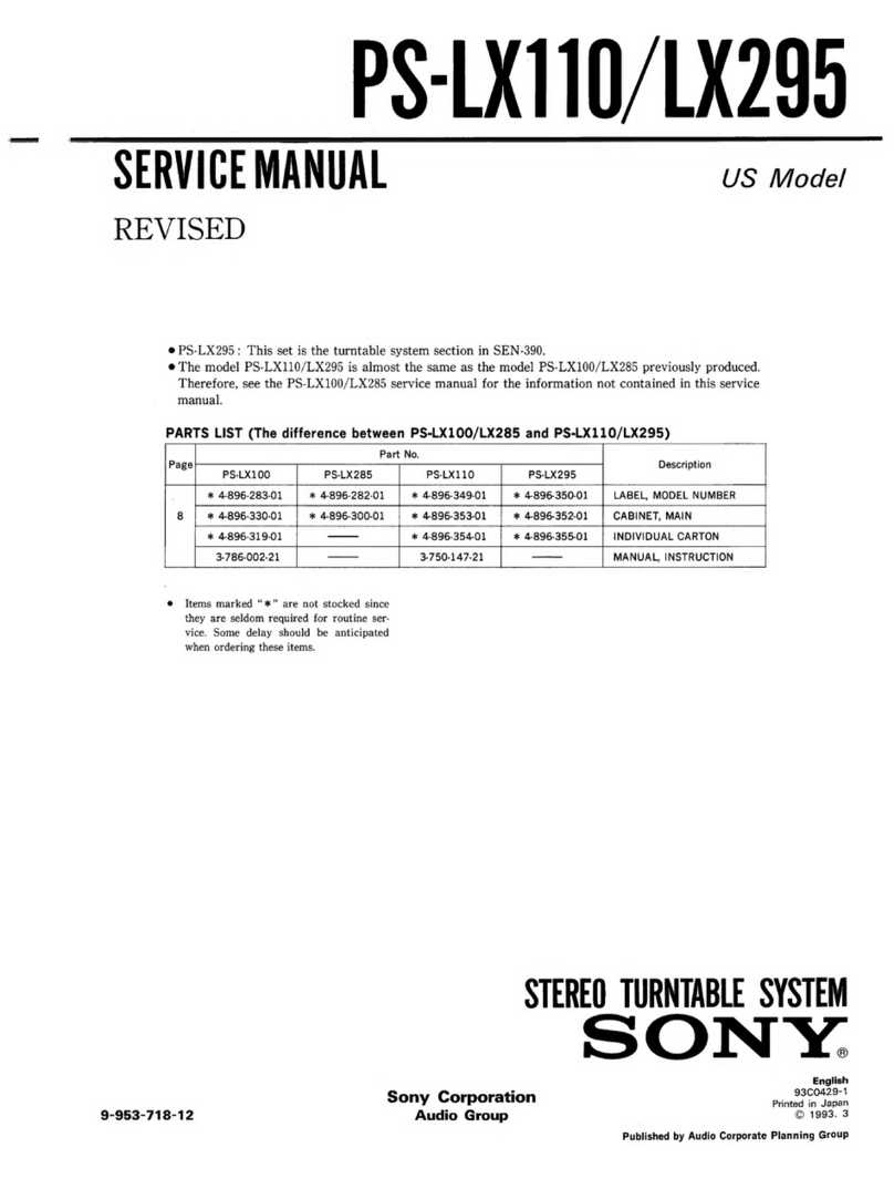
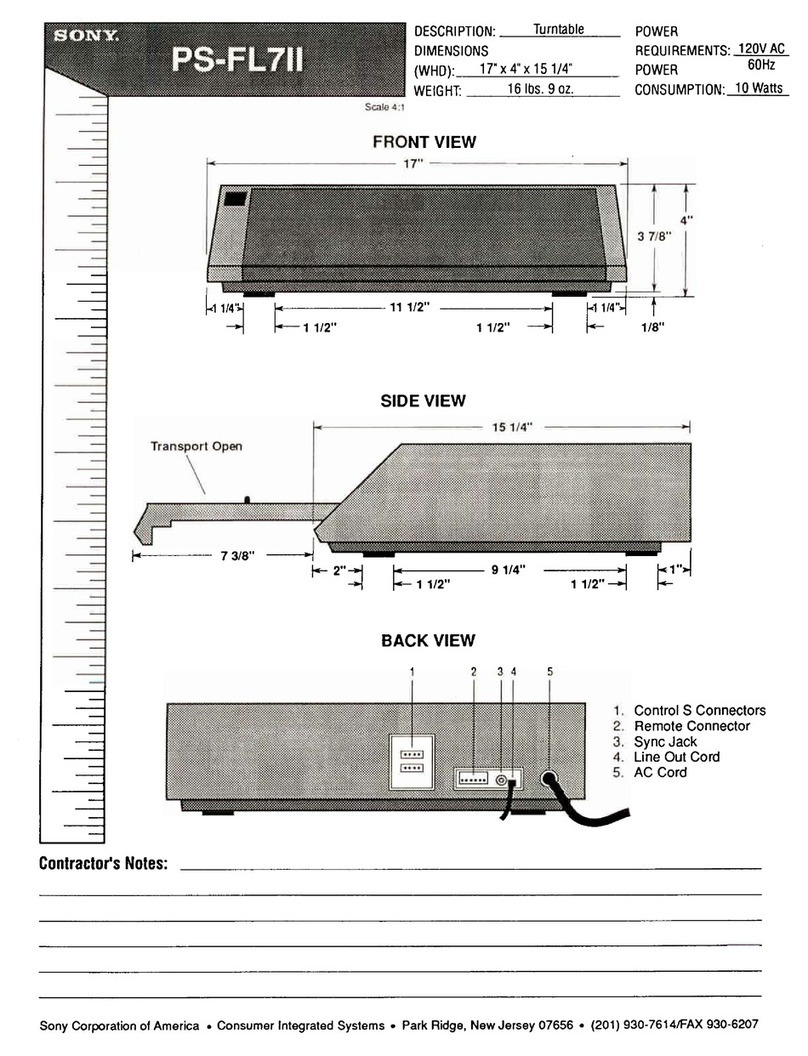
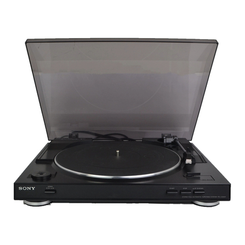
Sony PS-LX230 User manual

PS-LX230C
with
PS-LX-230.
VL-45G
cartridge
is
supplied
with
PS-LX230C,
while
VL-42G
cartridge
is
supplied
with
PS-L
X231.
Cartridge
is
not
supplied
PS-LX230:
US
Model
PS-LX230C:
US
Model
Canadian
Model
PS-LX231:
AEP
Model!
UK
Model
E
Model!
PS-LX231
SPECIFICATIONS
Tumtable
Platter
30.0
cm
(12
in.),
aluminum-alloy
diecast
Motor
DC
servo
motor
Drive
system
Belt
drive
Controlsystem
§DCservocontrol
system
Speed
3341/3
rom,
45
rpm
Starting
characteristics
Comes
to
nominal
speed
within
1/2
rotation
(334/3
rpm)
Wow
and
flutter
0.045%
(WRMS),
+
0.06%
(DIN)
Signal-to-noise
ratio
70
dB
(DIN-B)
Automatic
system
Return,
reject
Suspension
system
High
elasticity
gel
insulator
Tonearm
Type
PS-LX230/230C:
Statically
balanced
PS-LX231:
Dynamically
balanced
Pivot-to
stylus
length
|
216.5
mm
(83/2
in.)
SAFETY-RELATED
COMPONENT
WARNING!!
COMPONENTS
IDENTIFIED
BY
SHADING
AND
MARK
A
ON
THE
SCHEMATIC
DIAGRAMS
AND
IN
THE
PARTS
LIST
ARE
CRITICAL
TO
SAFE
OPERATION.
REPLACE
THESE
COMPONENTS
WITH
SONY
PARTS
WHOSE
PART
NUMBERS
APPEAR
AS
SHOWN
IN
THIS
MANUAL
OR
IN
SUPPLEMENTS
PUBLISHED
BY
SONY.
Cartridge
PS-LX230:
Not
supplied
PS-LX230C:
VL-45G
Type
Moving
magnet
type
Frequency
response
20Hz
to
20
kHz
Channel
separation
20
dB
at
1
kHz
Output
voltage
3.5mVat1kHz,5cm/sec.,
45°
Loadimpedance
50
to
100
kilohms
Tracking
force
1.259
Stylus
Sony
ND-145G
(conical
0.6
mil
diamond)
Weight
6g
—
Continued
on
page
2
—
ATTENTION
AU
COMPOSANT
AYANT
RAPPORT
A
LA
SECURITE!
LES
COMPOSANTS
IDENTIFIES
PAR
UNE
TRAME
ET
|
UNE
MARQUE
/\
SUR
LES
DIAGRAMMES
SCHE-
)
MATIQUES
ET
LA
LISTE
DES
PIECES
SONT
CRITIQUES
:
POUR
LA
SECURITE
DE
FONCTIONNEMENT.
NE
REM-
PLACER
CES
COMPOSANTS
QUE
PAR
DES
PIECES
SONY
DONT
LES
NUMEROS
SONT
DONNES
DANS
CE
MANUEL
OU
DANS
LES
SUPPLEMENTS
PUBLIES
PAR
SONY.
STEREO
TURNTABLE
SYSTEM
SONY.

PS-LX230/LX230€/LX231
PS-LX231:
VL-42G
Type
Moving
magnet
type
Frequency
response
20
Hz
to
20
kHz
Channel
separation
16
dB
at
1
kHz
Output
voltage
2.5mVat1kHz,5cm/isec.
Load
impedance
50to
100
kilohms
Tracking
force
2g
Stylus
Sony
ND-142G
(conical
0.6
mil
diamond)
Weight
8g
General
Power
requirements
US,
Canadian
model:
120
Vac,
60Hz
AEP
model:
220
Vac,
50/60Hz
(240V
ac
adjustable
by
authorized
Sony
personnel)
UK
model:
240V
ac,
50/60
Hz
(220V
ac
adjustable
by
authorized
Sony
personnel)
E
model:
110—120
or
220—240V
ac
adjustable,
50/60
Hz
Power
consumption
5W
Dimensions
Approx.
430
x
110
x
360
mm
(w/h/d)
(17
x
43/3
x
14
in.)
including
projecting
parts
and
controls
Weight
Approx.
3.5
kg
(7
Ibs
12
02),
net
MODEL
IDENTIFICATION
—
Specification
Label
—
PS-LX230
PS-LX231
SONY:
MODEL
NO.L____|
STEREO
TURNTABLE
SYSTEM
be
cnnennaesingancniiienscaed
SERIAL
NO.
MADE
IN
JAPAN
US,
Canadian
model:
AC:
120V60Hz
5W
AEP
model:
AC:
220V~50/60Hz
5W
UK
model:
AC:
240V~50/60Hz
5W
E
model:
AC:
110—120V,
220—240V~
50/60Hz
5W
SAFETY
CHECK-OUT
(US
Model)
After
correcting
the
original
service
problem,
perform
the
following
safety
check
before
releasing
the
set
to
the
customer:
Check
the
antenna
terminals,
metal
trim,
‘‘metallized”’
knobs,
screws,
and
all
other
exposed
metal
parts
for
AC
leakage.
Check
leakage
as
described
below.
LEAKAGE
TEST
The
AC
leakage
from
any
exposed
metal
part
to
earth
ground
and
from
all
exposed
metal
parts
to
any
exposed
metal
part
having
a
return
to
chassis,
must
not
exceed
0.5
mA
(S00
microampers).
Leakage
current
can
be
measured
by
any
one
of
three
methods.
1.
A
commercial
leakage
tester,
such
as
the
Simpson
229
or
RCA
WT-540A.
Follow
the
manufacturers’
instructions
to
use
these
instru-
ments.
2.
A
battery-operated
AC
milliammeter.
The
Data
Precision
245
digital
multimeter
is
suitable
for
this
job.
3.
Measuring
the
voltage
drop
across
a
resistor
by
means
of
a
VOM
or
battery-operated
AC
volt-
meter.
The
‘“‘limit’’
indication
is
0.75
V,
so
analog
meters
must
have
an
accurate
low-
voltage
scale.
The
Simpson
250
and
Sanwa
SH-63Trd
are
examples
of
a
passive
VOM
that
is
suitable.
Nearly
all
battery
operated
digital
multimeters
that
have
a
2
V
AC
range
are
suitable.
(See
Fig.
A)
To
Exposed
Metal
Parts
on
Set
AC
vo/tmeter
(0.75
V)
=
Earth
Ground
Fig.
A.
Using
an
AC
voltmeter
to
check
AC
leakage.
x
2
4
i
a
:
&
&
q
i

PS-LX230/LX230C/LX231
FUNCTION
OF
CONTROLS
PS-LX230/LX230C
The
(T4P}iabel
indicates
that
a
cartridge
is
a
standardized
plug-in
type.
IWlustration:
PS-LX230C
ANTI-SKATING
compensator
rc
&
se
$
Normally,
set
it
at
the
center
position.
If
the
stylus
is
driven
e
S$
Ss
Co
inward
when
the
tonearm
is
lowered-to
the
lead-in
groove,
o
PY
4
oF
turn
the
ANTI-SKATING
compensator
to
©.
If
the
stylus
is
<
fe
Fo
ras
outward,
turn
the
ANTI-SKATING
compensator
to
A
ia)
Center
position
TRACKING
FORCE
FINE
ADJUSTMENT
(PS-LX230/LX230C)
Tracking
force
is
a
vertical
force
applied
to
the
stylus
tip
so
that
it
can
accurately
trace
a
record
groove.
In
this
turntabie
system,
the
correct
tracking
force
is
obtained
when
the
sub-weight
is
at
the
@
position.
The
sub-weight
|
must
be
adjusted
if
the
following
irregurality
is
noticed.
If
the
stylus
skips
the
grooves,
set
the
sub-weight
towards
+.
If
the
tracking
force
is
too
heavy,
set
the
sub-weight
towards
-.
—
3
—

PS-LX230/LX230€/LX231
SECTION
1
DISASSEMBLY
Note:
Follow
the
disassembly
procedure
in
the
numerical
order
given.
Remove
dust
cover
and
turntable.
MOTOR
(M101)
REMOVAL
screw,
motor
BOTTOM
PLATE
REMOVAL
Remove
7
screws
(PTPWH
3
x
12)
of
bottom.
a
:
é
oy
motor
ARM
SECTION
REMOVAL
When
installing,
distance
between
center
of
micro
—
O
PTPWH3x6
switch
actuator
and
portion
*
of
switch
lever
is
7mm.
ee
|
center
of
micro
switch
actuator
@
plate
(upper),
shield
©
PTPWH3x
12
@
plate
(lower),
shield
Phono
board
Otis
sgh
ae
ae
See
a
ne
it
a
a
ee
Be
Te
six
lead
wire.
=2Z
©
Unsolder
A
>
LA
arm
section
oe
SagRS
EES
ea
he
i
tie

PS-LX230/LX230C€/LX231
ARM
PIPE
REMOVAL
(FOR
PS-LX230/LX230C)
@
joint,
center
O
P2x5
@
ground
plate
@
screw,
pivot—__
Koay
‘A
@
nut
(A),
lock,
wivor-
7
;
ON
F
Cpe——
@
screw,
pivot
@
nut
(A),
lock,
pivot
ARM
PIPE
REMOVAL
(FOR
PS-LX231)
PS3x6
Gs)
Q
joint,
center
ipe,
arm
shaft
assy,
rotary
O
Pip
@
pin,
horizontal

PS-LX230/LX230C/LX231
LEAD
WIRE
INSTALLATION
1.
Pass
piano
wire
with
lead
wires
through
pipe
as
shown
in
Fig.
A.
2.
Pass
piano
wire
with
lead
wires
through
center
joint
assy
as
shown
in
Fig.
B.
1
!
lead
wire
lead
wire
Piano
wire
————>
piano
wire
Joint
assy,
center
SECTION
2
ADJUSTMENTS
Speed
Adjustment
Note:
Be
sure
to
perform
45
rpm
adjustment
before
33
rpm.
—
Using
a
stroboscope
board
— —
Using
a
test
record
—
1.
Put
astroboscope
board
on
the
mat.
1.
Puta
test
record
(YFSC-16)
on
the
mat.
2.
Set
the
SPEED
switch
to
45.
2.
Move
the
arm
on
a-2
(3
kHz)
section
and
trace
Depress
the
lifter
knob
to
make
a
lift-up
mode
it.
and
move
the
arm
on
most
outer-groove
of
a
Adjust
RV102
so
that
the
frequency
is
4038
—
record:
4062
Hz.
Adjust
RV102
so
that
the
stripped
pattern
of
Set
the
SPEED
switch
to
33.
stroboscope
board
is
stationary.
Adjust
RV101
so
that
the
frequency
is
2991
—
Set
the
SPEED
switch
to
33.
3009
Hz.
Adjust
RV101
in
the
same
way.
ee
as
|
eer
photo:
AEP
model

Stylus
Height
Adjustment
1.
Put
a
test
record
(YFSC-16)
or
a
record
on
the
mat.
2.
Depress
the
lifter
knob
to
make
a
lifter-up
mode
and
move
the
arm
on
most
outer-groove
of
a
record.
Confirm
that
the
stylus
height
from
a
record
is
within
specification.
If
not,
turn
the
adjustment
screw.
3.
Move
the
arm
on
most
inner-groove
of
a
record
and
confirm
that
the
stylus
height
from
a
re-
cord
is
within
specification.
If
not,
turn
the
ad-
justment
screw
and
repeat
steps
2
and
3.
Specification:
4
—
12mm
(3/16
—
1/2
inch)
4—12mm
“HG
TITTTTIT
ITT
IT
record
oo
__
adjustment
screw
PS-LX230/LX230€/LX231
Automatic
Return
Position
Adjustment
1.
Puta
test
record
(YFSC-16)
on
the
mat.
2.
Set
the
SPEED
switch
to
33
and
move
the
tonearm
on
a
return
check
groove.
3.
Turn
the
adjustment
screw
so
that
the
tone-
arm
starts
to
return
at
count
of
4
—
10.
adjustment
screw
count
increase
count
decrease

PS-LX230/LX230€/LX231
SECTION
3
DIAGRAMS
1
2
3
4
5
6
T
8
3-1.
MOUNTING
DIAGRAM
—
Conductor
Side
—
A
(SWITCH
BOARD]
SiO!
SPEED
f
i
ae
US,
CANADIAN,
:
[SYSTEM
CONTROL
BOARD)
—
AEP
MODEL
———
7T
|
ac
|
IN
|
|
Nov
_220v
G
|
I20V.
240V
|
|
|
|
|
|
D
|
|
|
|
|
|
ee
ee
een
ee
eee
et
_]
7.5V
(33rpm)
6V
(33rpm)
6V
(45rpm)
4.6V
(45rpm)
=
ala
a5
pT
"ta
dy
wHT
Se
=
:
TO
HEAD
SHELL
BLK
een
reo
wat
BLU
$102
~
|
TO
TURNTABLE
>
BLK
[PHONO
BOARD)
=a:
3
WHT
SHAFT
—
Fh
L-ck
(GROUND)
TO
PIPE
JOINT
|
f
R-CH
|
RED
|
;
@
Semiconductor
Lead
Layouts
:
Note:
“PC1470H
1S$S202-1
S1RBA10
;
@
Color
code
of
sleeving
over
the
end
of
the
jacket.

PS-LX230/LX230C€/LX231
PS-LX230/LX230€/LX231
5
6
7
=
$
4
EXPLODED
VIEWS
AND
PARTS
LIST
3-2.
SCHEMATIC
DIAGRAM
:
NOTE:
*
The
mechanical
parts
with
no
reference
The
components
identified
|
Les
composants
identifiés
par
%
number
in
the
exploded
views
are
not
by
shading
and
mark
A
are
[
une
trame
et
une
marque
A
sont
=
supplied.
critical
el
safety.
he
os
pour
la
sécurité.
=
"
"
.
Replace
only
with
part
e
les
remplacer
que
par
US.
CANADIAN
-
Items
marked
"
*.
are
not
stocked
since
number
specified.
une
pi&ce
portant
le
numéro
"MODEL
they
are
seldom
required
for
routine
spécifié.
Some
d
e
1
ay
S
h
Ou
]
d
be
a
n
t
}
Cc
i
<
pens
Pateteteterateroteteereronereresetererelelatecereletalerereteteteteleteterstoreratererersraresarsrereceseresoceseserensceresesecscesesaseascecesestasessestaseseness
Satetatetaetacetatatatatatatenetetatatesetetetereeetatenee
et
rices
=
=
service.
Some
delay
should
be
antici-
=§-_—
a
csccssssssaaaanannennnnennenannassssassaasascccscaateaaananannannaanananseesesasae
soeesecessooosnoaaanananmanegy
h
items.
ttiti(i‘(itsCOCS
eee
DI02
1$$202-|
IC1Ol
pPCI470H
pated
when
ordering
these
ite
C103
:
Peer
*
The
construction
parts
of
an
assembled
330
part
are
indicated
with
a
collation
number
in
the
remark
column.
sot
33]
,
'
Ie
4-1.
44
(including
@A)
48
C104
10
r)
+
16V
;
DIO!
SIRBAIO
RECT
39
SPEED
~o
AOJ
0
45
6V(33
rpm)
4.6V(45rpm)
a
eee
pons
ioe
‘(SWITCH
BOARD)
sg
‘Bae
(SYSTEM
CONTROL
BOARD]
|
[PHONO
BOARD]
~-
WHT
Pe
(@)
L-CH
NS
51
(®)
R-CH
TO
TURNTABLE
SHAF
T(GROUND)
12
27
Note:
e
All
capacitors
are
in
uF
unless
otherwise
noted.
pF:
wuF
_
_
50WV
or
less
are
not
indicated
except
for
electrolytics
No.
Part
No.
Description
Remarks
|
No.
Part
No.
Description
Remarks
and
tantalums.
.
1
*4-908-151-01
BRACKET
(C),
MOTOR
30.
4-875-208-31
REST,
ARM
e
All
resistors
are
in
Q
and
1/,W
or
less
unless
otherwise
2
4-909-061-01
CUSHION,
MOTOR
31
3-703-136-00
SCREW
+PTPWH
3X12
-£:
3
4-909-062-01
SCREW,
MOTOR
32
7-624-133-54
STOP
RING
10,
TYPE-CE
cna
sa
4
4-903-339-01
GEAR,
DRIVE
33
4-881-633-00
(LX231)......-00.
KNOB
(I),
IFC
©
pwr:
fusible
resistor.
5
X-4852-007-2
CLUTCH
(B)
ASSY
4-903-333-01
(LX230/LX230C)...KNOB,
IFC
@
(1%):
tolerance
identification.
6
4-852-013-05
CLUTCH
(A)
34
4-844-041-00
WASHER,
(N)
e
(___]:
adjustment
for
repair.
7:
7-688-003-11
W
3,
MIDDLE
35.
4-903-323-01
CAM,
IFC
|
therwi
8
7-624-190-81
STOP
RING
2,
TYPE-CS
36
4-874-250-00
SPRING
Or
VOUBORS
ANG
Se
WMO
TESPEE
tO:
QrCUO
CHUM
er
en
icnwee
9
4-889-523-01
SHAFT,
CENTER
37
0-056-028-00
WASHER,
PLAIN,
14
DIA.
Ores:
A
10
7-624-133-34
STOP
RING
8,
TYPE-CE
38
X-4903-302-1
PLATE
ASSY,
UP
AND
DOWN
50
e
Readings
are
taken
under
no-signal
conditions
with
a
11
4-908-102-01
BEARING
39
*X-4903-416-1
TURNTABLE
ASSY
VOM
(50
k&Q/V).
12
4-908-101-01
HOLDER,
BEARING
40
4-858-264-21
LABEL,
CAUTION
;
13.
4-908-104-01
NUT,
BEARING
41
4-880-655-01
BELT
©
Voltage
variations
may
be
noted
due
to
normal
produc
14
4-908-141-01
RETAINER
(S),
THRUST
42
4-889-532-01
(AEP,UK,E)......PLATE,
BOTT(M
tion
tolerances.
15
4-875-214-00
LEVER,
SWITCH
4-889-532-11
(US,Canadian)...PLATE,
BOTTOM
i
16
*4-858-234-00
LEVER,
RETURN
43
4-857-653-00
HINGE,
DUST
COVER
Be
si
:
on
ee
=
17.
3-536-780-00
SPRING,
TENSION
(44°
~~
X-4903-415-1
COVER
ASSY,
DUST
45
==
Note:
The
components
identified
by
shading
and
mark
=
18
4-836-836-00
SPRING,
COMPRESSION
45
3-703-705-41
STICKER,
SONY
SYMBOL
(30)
aS
itical
for
safety.
Replace
only
with
==
19
3-701-508-00
SET
SCREW,
DOUBLE
POINT
3X6
46
3-701-806-00
ADAPTOR,
45,
(E)
falas
ge
ave
Y
P
*
.
20
7-682-553-09
SCREW
+B
3X20
47
4-874-262-00
GUIDE,
RECORD
part
n
Pp
:
21
4-889-525-31
(LX231).......0..
PANEL,
CONTROL
48
4-913-521-01
(Canadian,AEP
,UK,E)...SHEET,
TURNTABLE
saga
aaa
ascents
4-889-525-41
(LX230/LX230C)...PANEL,
CONTROL
4-913-521-11
(US).......e000006eeSHEET,
TWRNTABLE
Se
eee
22
4-861-933-00
SLEEVE
(D)
49
*4-903-462-01
(UK).......c000.
LABEL,
MODEL
NUMBER
Fi
eds
wh
Sy
ipo
aa
cata
eee
—P
Sts
ss
|
a
23.
4-812-554-00
WASHER
*4-903-463-01
(AEP).....
»+++.eLABEL,
MODEL
NUMBER
a
Note:
Les
composants
identifies
par
une
trame
et
une
eS
24
-7-685-152-14
SCREW
+P
3X25
TYPE2
SLIT
*4-903-464-01
(US,Canadian)...LABEL,
MODEL
NUMBER
ae
marque
/\
sont
critiques
pour
la
sécurité.
Ne
les
_
ee
een
Denes:
ee
*4-903-473-01
(E).......+.....+LABEL,
MODEL
NUMBER
iéce
portant
le
numéro
=
~301-64/-
,
50
7-621-738-08
SET-SCT,
HEX.
2.6X4,
FLAT
POI
NT
remplacer
que
paluine
Ricco?
7
27
-3-703-137-00
SCREW
+PTPWH
3X10
51
3-701-690-00
_(UK)....LABEL
(MADE
IN
JAPAN)
spécifie.
28
=4-881-608-21
KNOB,
REJECT
52
3-703-845-01
(US,Canadian,UK)...LABEL,
MAIN
CAUTION
SN
ee
a
ee
eee
29
3-533-014-00
SPRING,
COMPRESSION
53
4-876-344-00
(AEP)...LABEL,
CAUTION,
POWER
CORD
54
*4-881-683-00
(E).....
LABEL,
VOLTAGE
9
—10—
M101
8-835-126-01
MOTOR,
DC
(DNR-7600A)
HV
10V
7.5V(33rpm)
ity
R104
ik
6V
(45rpm)
1)
D102
(2)
H
[
J
J
AA
134-8
switch
board
al
No.
101
102
103
104
105
106
107
108
109
110
111
112
113
114
115
116
117
118
119
120
121
122
123
PS-LX230/LX230€/LX231
I
a
ve
b
4
I
CP
117
ze
e
T101
:
901
(including
4A,
B)
136
ss:
The
components
identified
|
Les
composants
identifiés
par
ee
=:
by
shading
and
mark
A
are
[
une
trame
et
une
marque
A
sont
Be
=
critical
for
safety.
critiques
pour
la
sécurité.
m
ss
Replace
only
with
part
Ne
les
remplacer
que
par
=
number
specified.
une
piéce
portant
le
numéro
spécifié.
Part
No.
Description
Remarks
|
No.
Part
No.
Description
Remarks
A-4637-063-A
ROD
ASSY
(P),
PUSH
102,103
124
7-685-152-14
SCREW
+P
3X25
TYPE2
SLIT
*4-876-317-00
GUIDE,
LIFTER
125
4-875-207-00
SLEEVE
7-621-741-09
SET-SCT,
HEX.
2.6X8
WP
126
4-870-785-00
SPRING,
TENSION
(MAIN
LEVER)
*4-903-321-01
LEVER
(G),
LIFTER
127
3-610-931-11
SPACER,
SHAFT,
DRUM,
HEAD
*4-903-317-01
LEVER
(F),
LIFTER
128
7-685-666-21
SCREW
+BVTP
4X30
TYPE2
SLIT
129.
=*4-889-524-01
PLATE
(LOWER),
SHIELD
4-881-642-00
SPRING,
COMPRESSION
130
7-623-422-07
LW
3,
TYPE
B
*4-881-611-00
SHAFT,
LEVER,
LIFTER
7-621-775-50
SCREW
+B
2.6X10
131
*4-889-526-01
PLATE
(UPPER),
SHIELD
*X-4877-805-6
LEVER
ASSY,
MAIN
132
*4-870-752-00
HOLDER,
SPRING
7-682-150-01
SCREW
+P
3X12
133.
*4-889-527-01
BRACKET,
SWITCH
134
7-621-775-08
SCREW
+B
2.6X3
4-889-531-41
FRAME
135
4-870-730-21
KNOB,
SPEED
4-903-331-01
SPRING
(LIFTER),
COMPRESSION
136
X-4903-301-1
INSULATOR
ASSY
*4-301-647-00
WASHER,
SPECIAL
3-703-136-00
SCREW
+PTPWH
3X12
901
*1-614-795-11
PC
BOARD,
SYSTEM
CONTROL
4-877-824-00
CAM,
LIFTER
902
*1-535-117-00
TERMINAL
*4-903-320-01
3-703-137-00
*4-875-205-00
4-875-204-00
3-491-240-00
*4-858-240-00
4-861-933-00
4-812-554-00
903
1-551-294-00
CORD
(WITH
PLUG)
RETAINER
(D),
LIFTER
SCREW
+PTPWH
3X10
PLATE,
FIXED
SPRING
SPRING,
TENSION
S101
1-570-166-11
SWITCH,
PUSH
(1
KEY)
LEVER
(M),
CLUTCH
S102
1-570-489-11
SWITCH,
MICRO
SLEEVE
(D)
WASHER
PS-LX230/LX230€/LX231
Pea
or
een
ee,
ee
goer
4-3.
No.
151
152
153
154
155
156
157
158
159
160
161
162
163
Part
No.
4-889-529-11
4-868-016-00
4-889-510-00
7-682-555-09
7-688-003-11
7-623-505-01
4-889-528-11
7-621-771-06
7-623-508-01
7-682-545-09
X-4881-605-1
4-880-619-00
3-701-437-01
Description
JOINT,
PIPE
HOOK
,
SPRING
SPRING,
TENSION
SCREW
+B
3X30
W
3,
MIDDLE
LUG,
2
PIPE,
ARM
SCREW
+B
2X5
LUG,
3
SCREW
+B
3X4
SHAFT
ASSY,
ROTARY
PIN,
HORIZONTAL
WASHER
stylus
tip
head
shell
Remarks
No.
164
165
166
167
168
905
906
907
—
2—
FOR
PS-LX231
Part
No.
4-880-631-11
7-682-647-09
3-706-613-00
*3-706-612-00
3-706-614-11
1-557-042-11
1-557-042-21
1-557-042-31
1-§57-042-41
1-549-109-21
1-549-112-00
Description
JOINT,
CENTER
SCREW
+PS
3X6
PROTECTOR
LABEL,
CARTRIDGE
SHELL
LEAD
(WITH
TERMINAL)
RED
LEAD
(WITH
TERMINAL)
GREEN
LEAD
(WITH
TERMINAL)
BLUE
LEAD
(WITH
TERMINAL)
WHITE
CARTRIDGE(WITH
SHELL)
(VL-42G)B
166-168,907
STYLUS
(ND-142G)
Remarks

4-4.
217
No.
Part
No.
201
*4-903-312-11
202
*4-903-308-01
203
4-903-336-11
204
*4-881-628-00
205
7-685-105-29
206
4-877-810-00
207
=
*4-903-350-01
208
7-685-134-14
209
*4-889-539-01
210
4-903-307-11
Description
FOR
PS-LX230/LX230C
WEIGHT,
SUB
SHEET
(S)
JOINT,
PIPE
REINFORCEMENT
(A)
SCREW
+P
2X8
TYPE2
SLIT
WEIGHT
WEIGHT,
SUPPORT
SCREW
+P
2.6X8,
TYPE2
NON-SLIT
PLATE,
GROUND
PIPE,
ARM
—
3—
Remarks
No.
211
212
213
214
215
216
21/7
908
909
910
Part
No.
7-621-771-06
X-4881-604-6
4-881-618-00
2-203-518-61
2-203-519-00
4-887-481-01
4-903-347-00
*1-562-517-41
1-549-11
721
1-549-118-00
Description
PS-LX230/LX230C/LX231
Remarks
SCREW
+B
2X5
JOINT
ASSY,
CENTER
BEARING,
PIVOT
SCREW,
PIVOT
NUT
(A),
LOCK,
PIVOT
(LX230C)...SCREW
(B),
CARTRIDGE
FITTING
(LX230C)...PROTECTOR
CONNECTOR
(WITH
HEAD
SHELL)
4P
(LX230C)...CARTRIDGE
(VL-45G)(B)
(LX230C)...STYLUS
(ND-145G)
910

PS-LX230/LX230C/LX231
NOTE:
Items
marked
"
*
"
are
not
stocked
since
they
are
seldom
required
for
routine
Some
delay
should
be
antici-
service.
pated
when
ordering
these
items.
-
If
there
are
two
or
more
same
circuitsin
a
set
such
as
a
stereophonic
machine,
only
typical
circuit
parts
may
be
indicated
and
capacitors
and
resistors
in
other
same
circuits
may
be
omitted.
Ref
.No.
901
902
903
906
907
908
909
910
C101
C102
C103
C104
D101
D102
[C101
M101
R102_
R103
R104
RV101
RV102
$101
$102
ELECTRICAL
PARTS
Part
No.
*1-614-795-11
*1-535-117-00
1-551-294-00
1-557-042-21
1-557-042-31
1-557-042-41
1-549-109-21
1-549-112-00
*1-562-517-41
1-549-117-21
1-549-118-00
1-123-336-00
1-123-380-00
1-123-309-00
1-123-356-00
8-719-510-01
8-719-107-94
8-759-103-35
8-835-126-01
1-214-721-00
1-214-729-00
1-226-233-00
1-226-232-00
1-570-166-11
1-570-489-11
PC
BOARD,
SYSTEM
CONTROL
TERMINAL
CORD
(WITH
PLUG)
Description
..
LEA
(LX231)...LEAD
(WITH
TERMINAL)
GREEN
(LX231)...LEAD
(WITH
TERMINAL)
BLUE
(LX231)...LEAD
(WITH
TERMINAL)
WHITE
D
(WIT
SECTION
5
ELECTRICAL
PARTS
LIST
CAPACITORS:
MF:uF,
PF:uuF.
RESISTORS
-
All
resistors
are
in
ohms.
*
F
:
nonflammable
=
by
shading
and
mark
A\are
==
critical
for
safety.
;
Replace
only
with
part
==
number
specified.
a8
==
Les
composants
identifies
par
=
COILS
et
mS
-
MMH
:
mH,
UH
:
vH
==
une
trame
et
une
marque
f\sont
2s
==
critiques
pour
la
sécurite.
=
SEMICONDUCTORS
=
Ne
les
remplacer
que.
par
=:
In
each
case,
U
:
u,
for
example:
oat
8
tant
]
Sms
UA...:
wA...,
UPA...:
uPA...,
UPC...:
uPC,
2
UNE
Prece
portant
le
numero
=:
UPD...:
UPD...
=
specifie.
a
ACCESSORY
&
PACKING
MATERIAL
Part
No.
Description
565-00.
(E)....AC
PL
3-701-616-00
(LX230)...BAG,
POLYETHYLENE
(FOR
SCREW)
3-701-630-00
BAG,
POLYETHYLENE
(FOR
INSTRUCTION
MANUAL
)
en
ee
3-701-634-00
BAG,
POLYETHYLENE
(FOR
TURNTABLE)
RO
PLUG
3-701-806-00
ADAPTOR,
45,
(E)
R
3-703-450-01
(US)...INSTRUCTION
(FOR
SAFETY
CAUTION)
:
3-765-234-11
(UK,E)....MANUAL,
INSTRUCTION
H
TERMINAL)
RED.
eae
3-765-234-41
3-765-234-21
(LX231)...CARTRIDGE(WITH
SHELL)
(VL-42G)B
(LX231)...STYLUS
(ND-142G)
ESE
ea
(AEP)...MANUAL,
INSTRUCTION
(US)....MANUAL
,
INSTRUCTION
(Canadian)...MANUAL,
INSTRUCTION
LABEL,
CAUTION
(FOR
DRIVE
GEAR)
(LX230)...
INSTRUCTION
(FOR
SCREW)
GUIDE,
RECORD
SHEET,
PROTECTION
(FOR
SET)
PLATE,
PROTECTION
(FOR
FRAME
SIDE)
(LX230)...SCREW
(B),
CARTRIDGE
FITTING
CUSHION
(LEFT)
CUSHION
(RIGHT)
HOLDER,
TURNTABLE
(LX230
,LX230C)...HOLDER,
ARM
1-214-717-00
(LX230,LX230C)..
CONNECTOR
3-765-234-31
(WITH
HEAD
SHELL)
4P
3-794-123-11
(LX230C)...CARTRIDGE
(VL-45G)(B)
3-795-753-21
(LX230C)...STYLUS
(ND-145G)
4-874-262-00
ELECT
470MF
20%
25
4-876-352-00
ELECT
1MF
20%
100V
4-881-698-00
ELECT
330MF
20%
10
4-887-481-01
ELECT
10MF
20%
50V
4-889-536-01
DIODE
S1RBA1O
4-889-537-01
DIODE
1$S202-1
4-889-538-01
IC
UPC1470H
4-903-348-01
MOTOR,
DC
(DNR-7600A)
4-903-468-41
——
4-903-468-51
BL
Ad
St
4-903-468-61
L
330
1%
METAL
470
1%
1/4W
4-913-521-01
METAL
IK
1%
1/4W
4-913-521-11
(US)
RES,
ADJ,
CARBON
1K
RES,
ADJ,
CARBON
500
*X-4903-416-1
SWITCH,
PUSH
(1
KEY)
SWITCH,
MICRO
9-952-176-11
Sony
Corporation
gazs
1
4—
(LX231)....
INDIVIDUAL
CARTON
(LX230)....
INDIVIDUAL
CARTON
(LX230C)...
INDIVIDUAL
CARTON
(Canadian,AEP
,UK,£)...SHEET,
TURNTABLE
SHEET,
TURNTABLE
TURNTABLE
ASSY
English
86E0670-1
Printed
in
Japan
©
1986
This manual suits for next models
2
Table of contents
Other Sony Turntable manuals

Sony
Sony PS-F5 User manual

Sony
Sony PS-LX300USB - USB Stereo Turntable System User manual

Sony
Sony PS-X6 Setup guide

Sony
Sony PS-X6 User manual

Sony
Sony MDX-F5800 User manual

Sony
Sony WALKMAN NW-ZX505 User manual

Sony
Sony DD-10EX User manual

Sony
Sony D-F181 - Fm/am Portable Cd Player User manual

Sony
Sony PS-LX250H User manual

Sony
Sony PS-LX310BT User manual