1
RS-232C PROTOCOL MANUAL
1. Communication Parameter
Communication system RS-232C
Synchronous system Asynchronous communication
Baud rate 9600 bps
Character length 8 bit
Parity None
Start bit 1 bit
Stop bit 1 bit
Flow control None
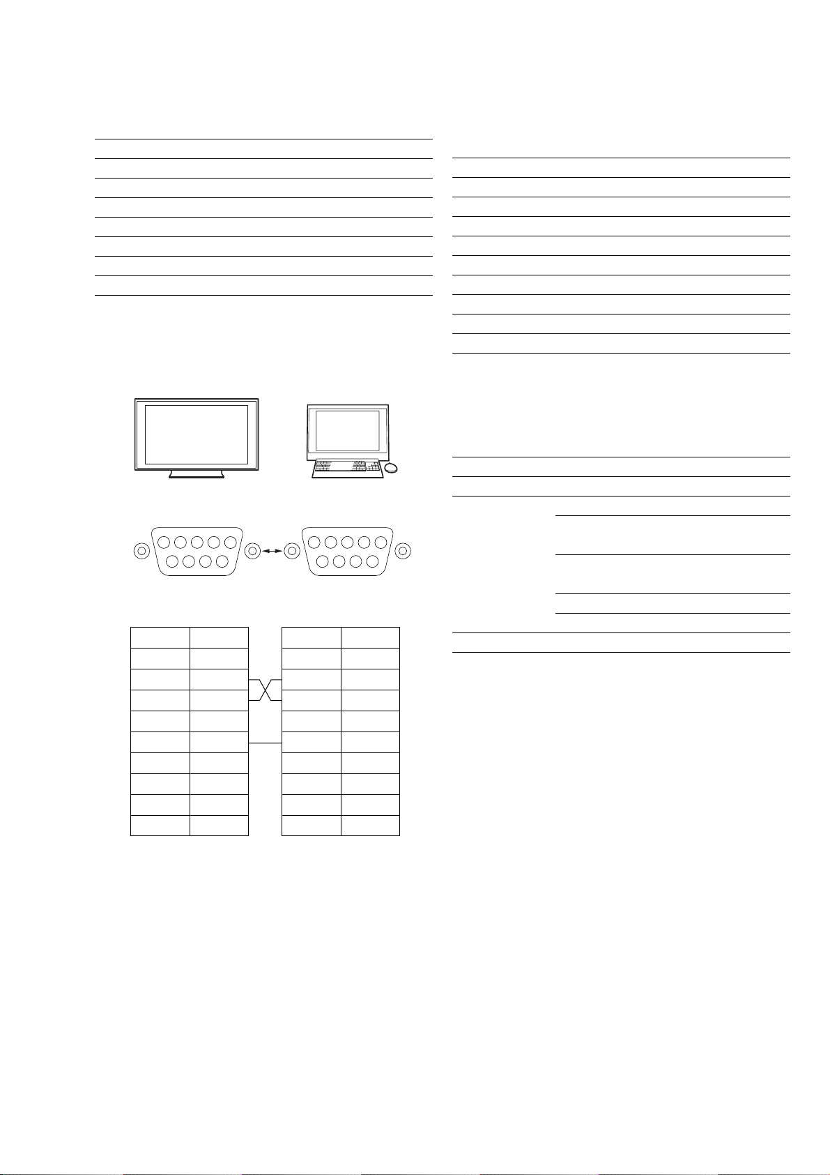
2. Pin Configuration
No. Item Value
1Header 0x70: Answer
2Answer* 0x00: Completed (Normal End)
0x01: Limit Over
(Abnormal End-Exceed maximum value)
0x02: Limit Over
(Abnormal End-Exceed minimum value)
0x03: Command Canceled (Abnormal end)
0x04: Parse Error (Data Format Error)
3Check Sum 0xXX
(b) Answer (Display tResponse to host)
1Control answer
∗0x00: Completed Normal response.
0x01: Limit Over The packets was received normally, but the
data value was over the upper limit.
0x02: Limit Over The packets was received normally, but the
data value was over the lower limit.
0x03: Command canceld The packet is received normally but either the
value of data is incorrect or request is not
permitted for the current host value.
0x04: Parse Error Received not defined format data or check
sum Error.
∗Check Sum:The total from No.1 to No. X, when value exceeds 255, 1byte
of data is confirmed the bottom.
4. Communication Data Format
No. Item Value
1Header 0x8C: Control
2Category 0x00 (fixed)
3Function 0xXX
4Data1 (Length) 0xXX (=X–3 byte)
5Data2 (Data1) 0xXX
:: 0xXX
:: 0xXX
XData (X-3) 0xXX
X+1 Check Sum 0xXX
(a) Control (Host tRequest ofWrite to Display)
∗Check Sum:The total from No.1 to No. X, when value exceeds 255, 1byte
of data is confirmed the bottom.
Display side (D-sub 9-pin male) Host side (D-sub 9-pin)
Personal computerKDL-52XBR5 etc.
KDS-Z70XBR5 etc.
-
External view
--
External view
-
54321
6789
54321
6789
Pin No.
1
2
3
4
5
6
7
8
9
Signal
NC
RD
TD
NC
GND
NC
NC
NC
NC
Pin No.
1
2
3
4
5
6
7
8
9
Signal
NC
RD
TD
NC
GND
NC
NC
NC
NC
3. Restriction for Communication
∗Send control command after 20 seconds of power on.
∗Strictly keep to send next command after receiving answer response from
Display.
∗Set the command interval to 500ms or more.
∗Value range for direct command is same as user can change by menu.
∗When set is at standby mode, only receives Power ON command.
∗To turn on the set, first set standby command as Enable. After this, the set
can receive Power ON command.