6XGS 4300/4500
Operating Instructions
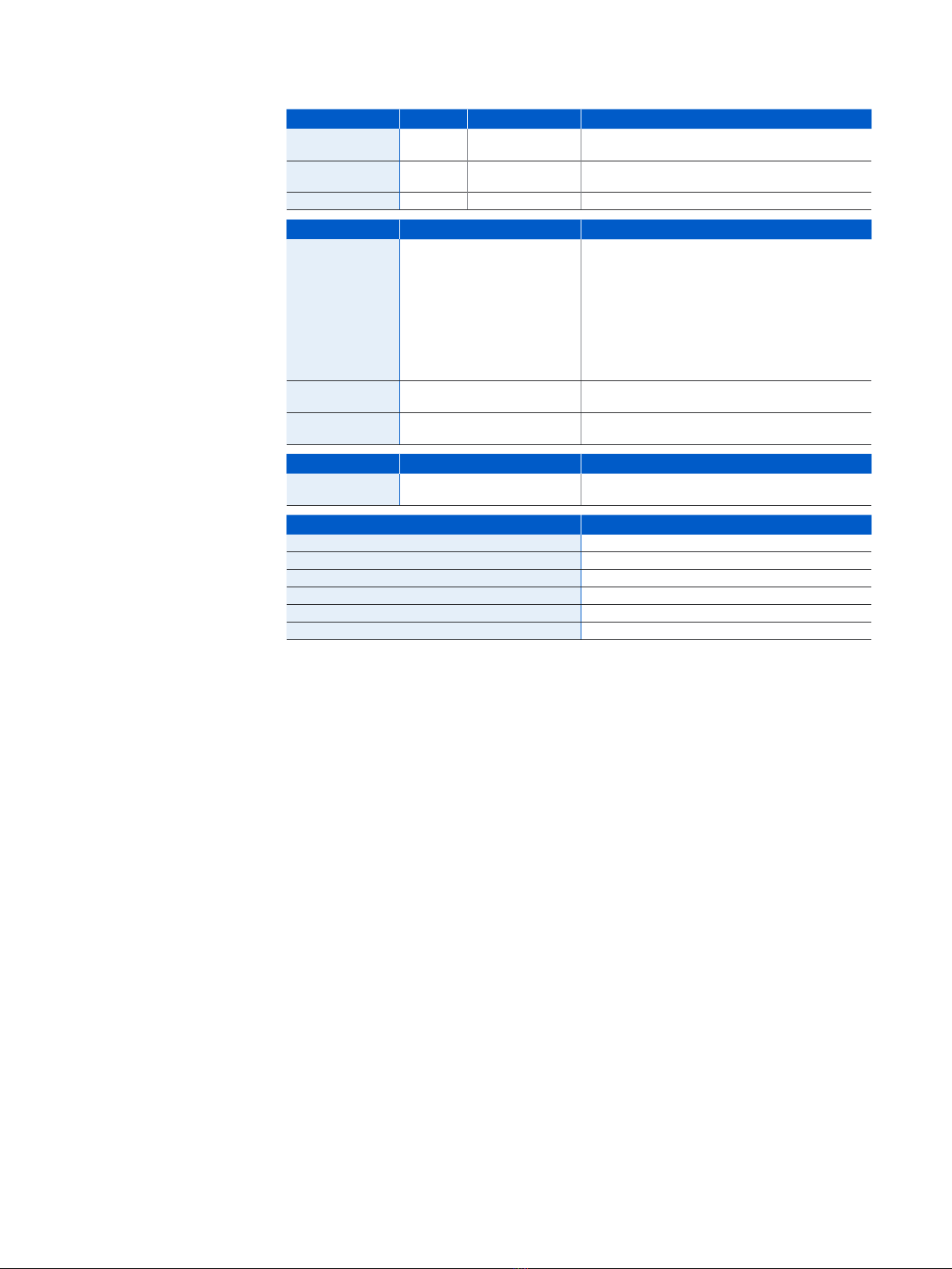
LED Status
Status LEDs
Power 1 Green Solid Power Supply 1 Active.
Red Solid Power Supply 1 Failure.
Power 2 Green Solid Power Supply 2 Active.
Red Solid Power Supply 2 Failure.
SSD Blue Flashing SSD reading/writing data.
BP 1/2 Green Solid Bypass mode on Ports 1/2 enabled.
Off Bypass mode on Ports 1/2 disabled and inactive.
BP 3/4 Green Solid Bypass mode on Ports 3/4 enabled.
Off Bypass mode on Ports 3/4 disabled and inactive.
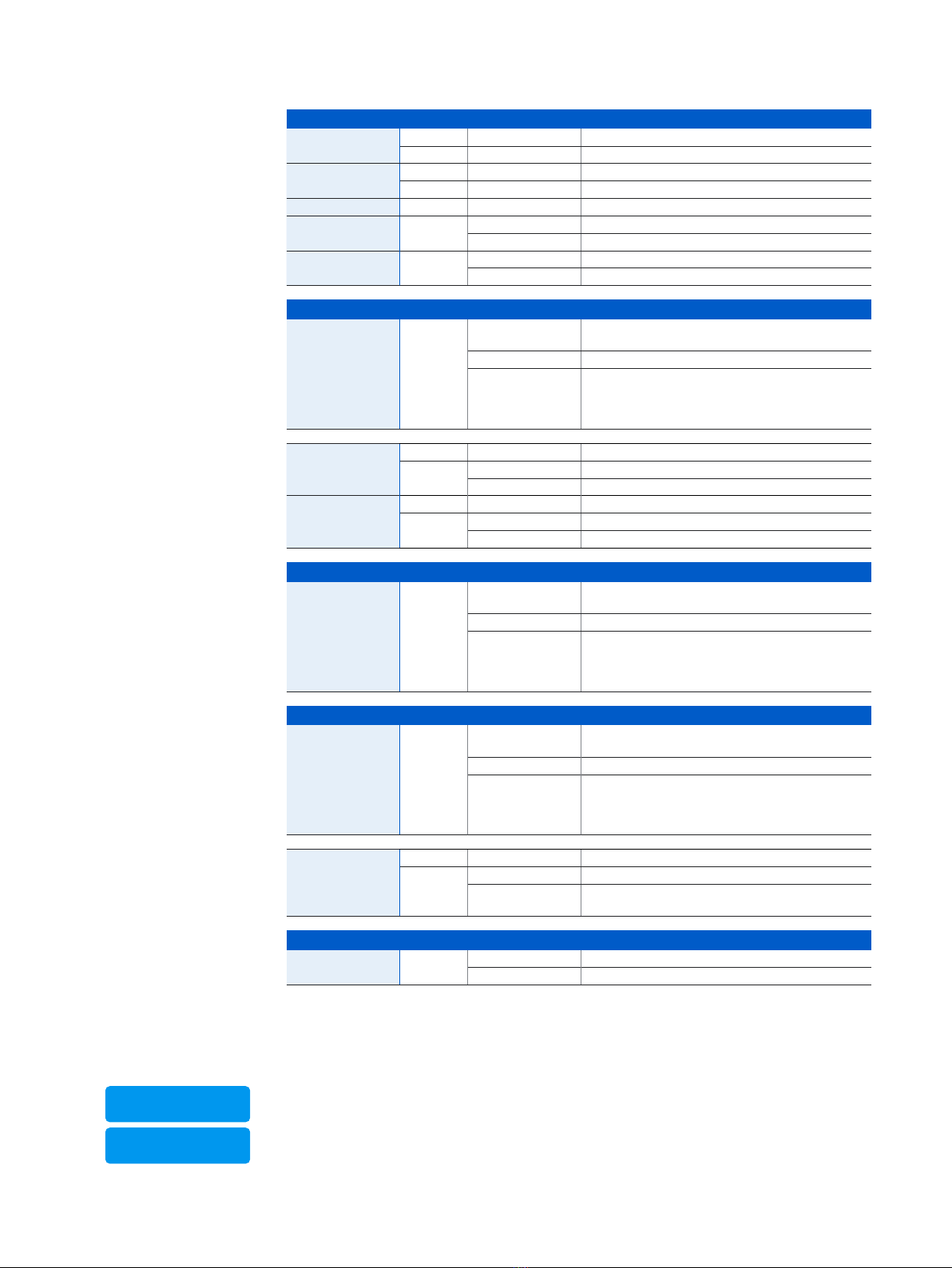
LEDs on each RJ45 Ethernet connector
ACT/LNK
(Left LED)
Green Solid 1. The Ethernet port has established link.
2. Good connection between the Ethernet port and hub.
Flashing The adapter is sending or receiving network data.
Off 1. The adapter and switch are not receiving power.
2. No connection between both ends of network.
3. Network drivers have not been loaded
or do not function correctly.
Speed
(Right LED)
1 GbE ports
Amber On If Ethernet port is operating at 1000 Mbps.
Green On If Ethernet port is operating at 100 Mbps.
Off If Ethernet port is operating at 10 Mbps.
Speed
(Right LED)
2.5 GbE ports
Amber On If Ethernet port is operating at 2500 Mbps.
Green On If Ethernet port is operating at 1000 Mbps.
Off If Ethernet port is operating at 100 Mbps.
LEDs on each SFP connector
ACT/LNK Green Solid 1. The SFP connector is receiving power.
2. Good connection between the SFP port and hub.
Flashing The adapter is sending or receiving network data.
Off 1. The adapter and switch are not receiving power.
2. No connection between both ends of network.
3. Network drivers have not been loaded
or do not function correctly.
LEDs on each SFP+ connector
ACT/LNK Green Solid 1. The SFP+ connector is receiving power.
2. Good connection between the SFP+ port and hub.
Flashing The adapter is sending or receiving network data.
Off 1. The adapter and switch are not receiving power.
2. No connection between both ends of network.
3. Network drivers have not been loaded
or do not function correctly.
Speed Blue On If SFP+ connector is operating at 10,000 Mbps.
Amber On If SFP+ connector is operating at 1,000 Mbps.
Off Either the LED is not working or the SFP+ connector
is operating at a speed below 1,000 Mbps.
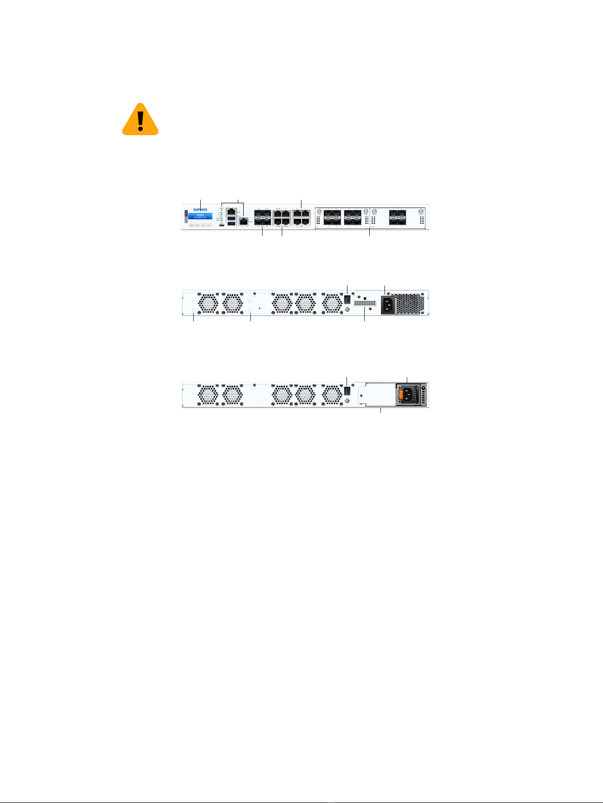
Back side
Power Supply
[XGS 4500 only]
Green Solid Power
Off No power
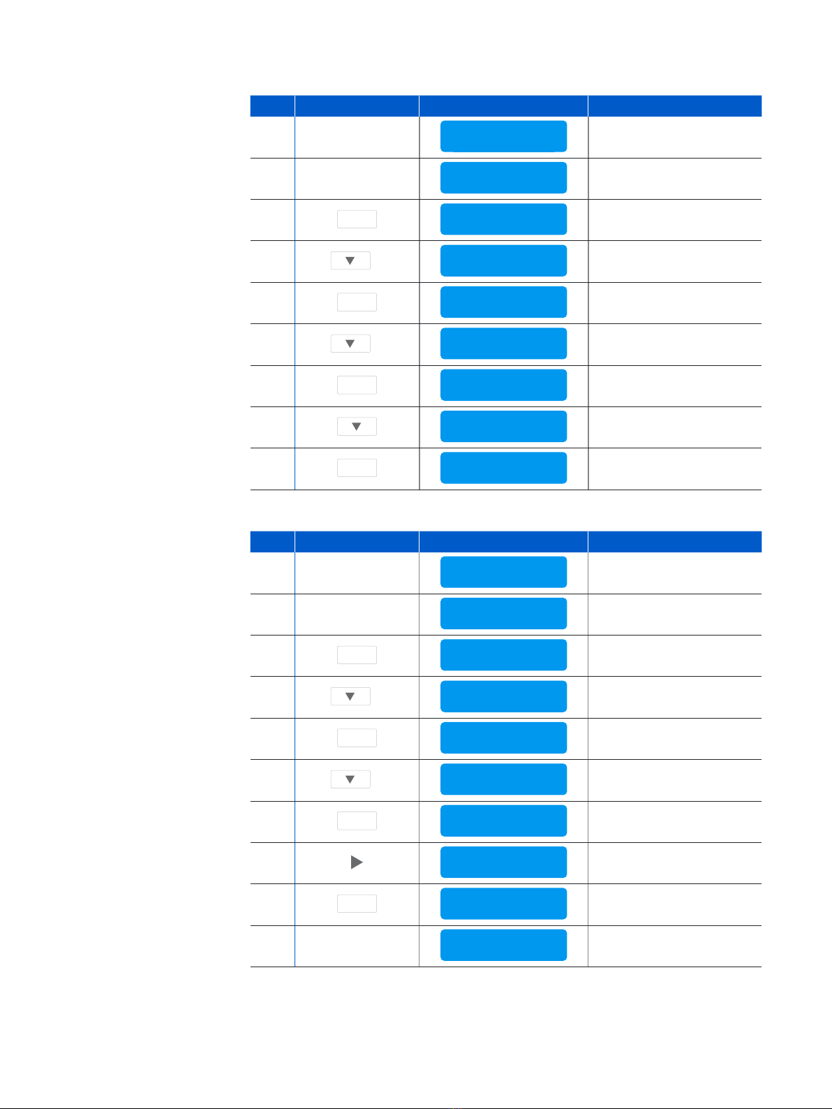
LCD and Control Keys
The XGS 4300/4500 have an LCD and an operating unit with four membrane keys. In the
LCD, 16 characters per line can be displayed.
While the security appliance is booting this message is displayed
Firmware Version
SOPHOS
Protection
Firmware Version
SFOS xx.xx.xx