SoRoTo 120L User manual
MANUAL
FORCED ACTION MIXERS GB-04.12.18
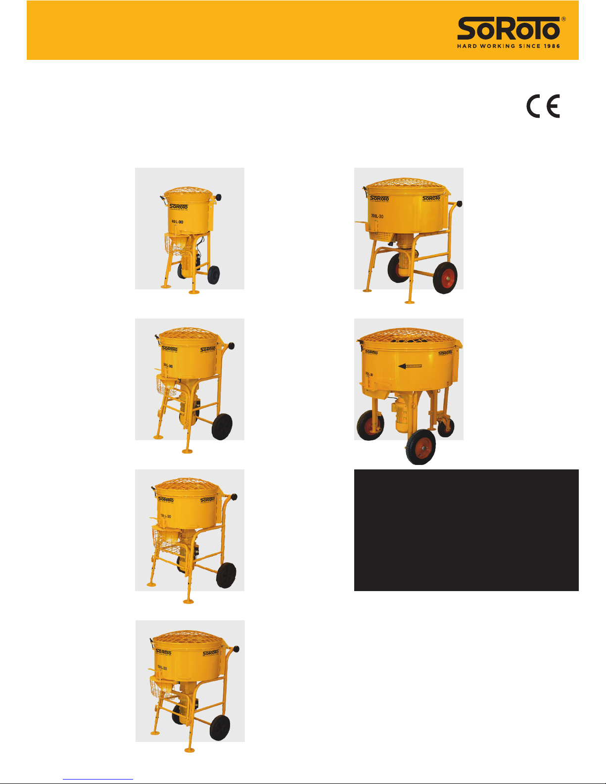
MODEL 40L
Mixing capacity:
40 litres
MODEL 80L
Mixing capacity:
80 litres
MODEL 100L
Mixing capacity:
100 litres
MODEL 120L
Mixing capacity:
120 litres
THE RIGHT MODEL AND
SIZE DO MATTER.
FOR ANY JOB BIG OR SMALL
SOROTO OFFERS THE RIGHT
ONE.
English

3 / GBGB / 2
TABLE OF CONTENTS
SoRoTo 40L, 80L, 100L, 120L.....................................p. 3
Application .....................................................................p. 3
Before use.......................................................................p. 3
Before connecting the power supply ..............p 3
Operating the SoRoTo forced action mixer ...p. 3
Cleaning / maintenance...........................................p. 4
Transport .........................................................................p. 4
Safety ................................................................................p. 4
Technical data ...............................................................p. 6
Contact details .............................................................p. 6
Special features/spare parts..................................p. 7
Spare part list – 40 L .................................................p. 8
Spare part list – 80 L .................................................p. 10
Spare part list – 100 L ...............................................p. 12
Spare part list – 120 L................................................p. 14
SoRoTo 200L, 300L........................................................p. 16
Application .....................................................................p. 16
Before use.......................................................................p. 16
Before connecting the power supply ..............p 16
Operating the SoRoTo forced action mixer ...p. 16
Adjusting the phase turner.....................................p. 17
Cleaning / maintenance...........................................p. 17
Transport .........................................................................p. 18
Safety ................................................................................p. 19
Technical data ...............................................................p. 19
Contact details .............................................................p. 19
Spare part list – 200 L ..............................................p. 20
Spare part list – 300 L ..............................................p. 22
EU Declaration of Conformity....................................p. 24
MANUAL APPLIES TO
SoRoTo 40L, 80L, 100L, 120L
APPLICATION
The SoRoTo Forced Action Mixers are ideal for mixing all kinds of materi-
als used in the building industry, as well as for tasks where high demands
are imposed on the quality of the mix.
When mixing materials containing aggregates, we recommend using the
SoRoTo Mixer system with rubber blades. (NOTE: The SoRoTo Forced
Action Mixer 40L is not suited for mixing materials containing aggre-
gates).
When using steel blades to mix materials containing aggregates, the
mixer arms may work their way upwards and eventually stop turning.
BEFORE USE
Before starting the mixer, the telescopic legs must be positioned for
the right height for draining into a bucket or wheelbarrow. The easiest
way for adjusting the legs is to lay down the mixer, so it rests on all four
wheels. The legs are released and locked with the fitted lock splits/bolts.
BEFORE CONNECTING THE POWER SUPPLY
Before the power is connected, the mixer arms must be set in place, and
the lid must be closed. The safety grid in front of the mixer gate must be
attached at all times.
For your safety, please always follow the instructions listed above before
use.
OPERATING THE SOROTO FORCED ACTION MIXER
Close the lid and lock it into place using the rubber strap. Start the mixer
by pressing the green START button on the protective motor switch.
Pour the required material into the drum and add liquid.
The protective motor switch has a zero voltage releaser. In case of power
failure, the mixer must be restarted. For safety reasons, the mixer will not
start if the lid is open.
5 / GBGB / 4
NOTE
Never put your hand or any object into the machine when the power is
connected.
When the material has reached the desired consistency and the mix-
ing motion is finished, the mixing drum is emptied by opening the mixer
gate. The drum should be emptied right after mixing. Please observe that
the material may set in the mixing drum, if left too long.
NOTE
The safety grid should be in front of the output gate at all times. If the
machine is jammed, e.g. by larger stones, ensure that the plug is discon-
nected from the protective motor switch, before removing the obstruc-
tion. Do not put your fingers or any object through the mixer gate.
CLEANING / MAINTENANCE
Before cleaning the mixer, the plug must be removed from the socket.
Open the lid and lift the mixing blades o the axle. The mixer arms are
easily removed without using tools.
Firstly wash the mixer arms and the entire mixing drum using water.
When cleaning has ended, place the mixer arms onto the axle and close
the lid.
TRANSPORT
During transport of the SoRoTo Forced Action Mixer it is recommended
that the mixer is placed on the four wheels, and the lid is closed and
locked with the rubber strap.
SAFETY
When using an extension cable, please observe the following,
• Never use a longer cable than max 10 m.
• Always use a cable with a minimum dimension of 1 mm2.
• Never use the cable when it is rolled up. Always roll it out completely.
When mixing materials that emit unpleasant or dangerous vapours and/
or dust, a dust controller is recommended.
SMALL LOADING
WHEELS
and the use of customized
lowered nuts mean you
can easily load the ma-
chine onto the truck. Even
the biggest machines are
easy to handle
OPTIONAL
DUST CONTROLLER
helps avoiding dangerous dust
discomfort - without losing the
opportunity to keep an eye on the
mixture, as you do with a closed
forced action mixer
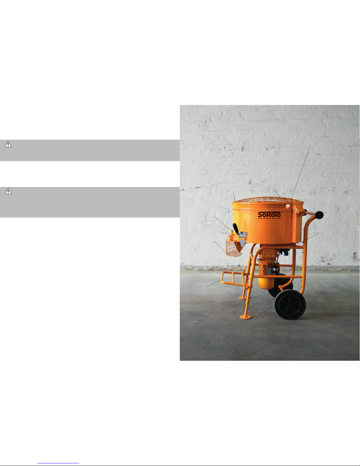
GEAR MOTOR
selected under the
motto:
maximum power
— minimum load.
A powerful motor
which, on the other
hand, has the lowest
possible ampere
consumption, so the
strain on the power
grid and the environ-
ment is minimized
SAFETY GRID
in front of the
discharge chute,
together with the
safety switch, en-
sure that you do
not risk harming
yourself in the
working machine
SPARE POWER OUTLET
Models 200L and 300L
are equipped with a spare
power outlet for work
lighting, industrial
vacuumcleaner,
belt conveyor or the like
BRACKET
is mounted on
every machine
for holding a
brick trowel
BUCKET
STAND
All 240V
machines are
equipped
with a robust
bucket stand
for a masonry
bucket TELESCOPIC
LEGS
ensure the right
working height
WHEELS
the mixer is
easily moved
from one place
to another on
the construction
site without any
use of a vehicle
OPTIONAL
TURBO ARM
Can be mounted on the 300L mixer
(e.g. for masonry mortar)
DISTINCTIVE SOROTO
MIXER ARMS
are removed without tools
facilitates cleaning and
replacement. Also avail-
able with rubber blades for
mixes containing
aggregates
RUBBER STRAP
The machines are
equipped with a rubber
strap that ensure that the
grid lid does not open
during use or transport
the original and some extra
7 / GBGB / 6
TECHNICAL DATA
Model 40L/30
Motor: 230V/110V - 0.75 kW – 50 Hz
W/L/H: 60*60*85 cm
Mixing capacity: 40 L.
Weight: 64 kg (empty).
LAeq< 75dB(A) with mortar.
Dust controller is not an option
Model 80L/30
Motor: 240V/110V - 1.1 kW – 50 Hz
W/L/H: 60*75*106 cm
Mixing capacity: 80 L.
Weight: 88 kg (empty).
LAeq< 75dB(A) with mortar.
Prepared for mounting of dust controller
Model 100L/30
Motor: 240V/110V - 1.1 kW – 50 Hz
W/L/H: 68*80*106 cm
Mixing capacity: 100 L.
Weight: 98 kg (empty).
LAeq< 75dB(A) with mortar.
Prepared for mounting of dust controller
Model 120L/30
Motor: 240V/110V – 1.1 kW – 50 Hz
W/L/H: 72*95*118 cm
Mixing capacity: 120 L.
Weight: 105 kg (empty).
LAeq< 75dB(A) with mortar.
Prepared for mounting of dust controller
TECHNICAL SUPPORT / WAREHOUSE
Fabriksparken 11
DK-2600 Glostrup
Tel. +45 3672 7800
teknik@soroto.dk
SALES / ADMIN
Fabriksparken 13
DK-2600 Glostrup
Tel. +45 3672 7500
soroto@soroto.dk
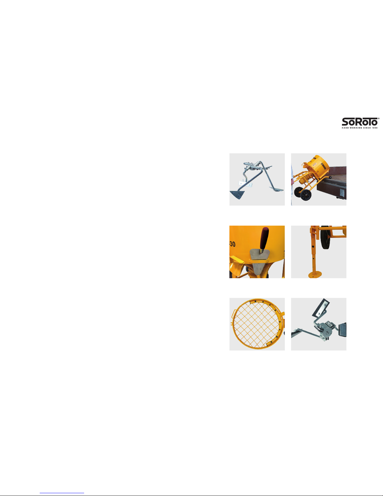
INCLUDING
Mixer arms with steel blades
and cross joint
INCLUDING
Bracket for holding a brick
trowel
OPTIONAL
Dust controller for better OSH*.
Available for 80-300 L mixers
INCLUDING
Small loading wheels
for easy on-/unloading
INCLUDING
Telescopic legs for setting the
right working hight
OPTIONAL
Rubber blades for mixes
containing aggregates
* Occupational Safety and Health
9 / GBGB / 8
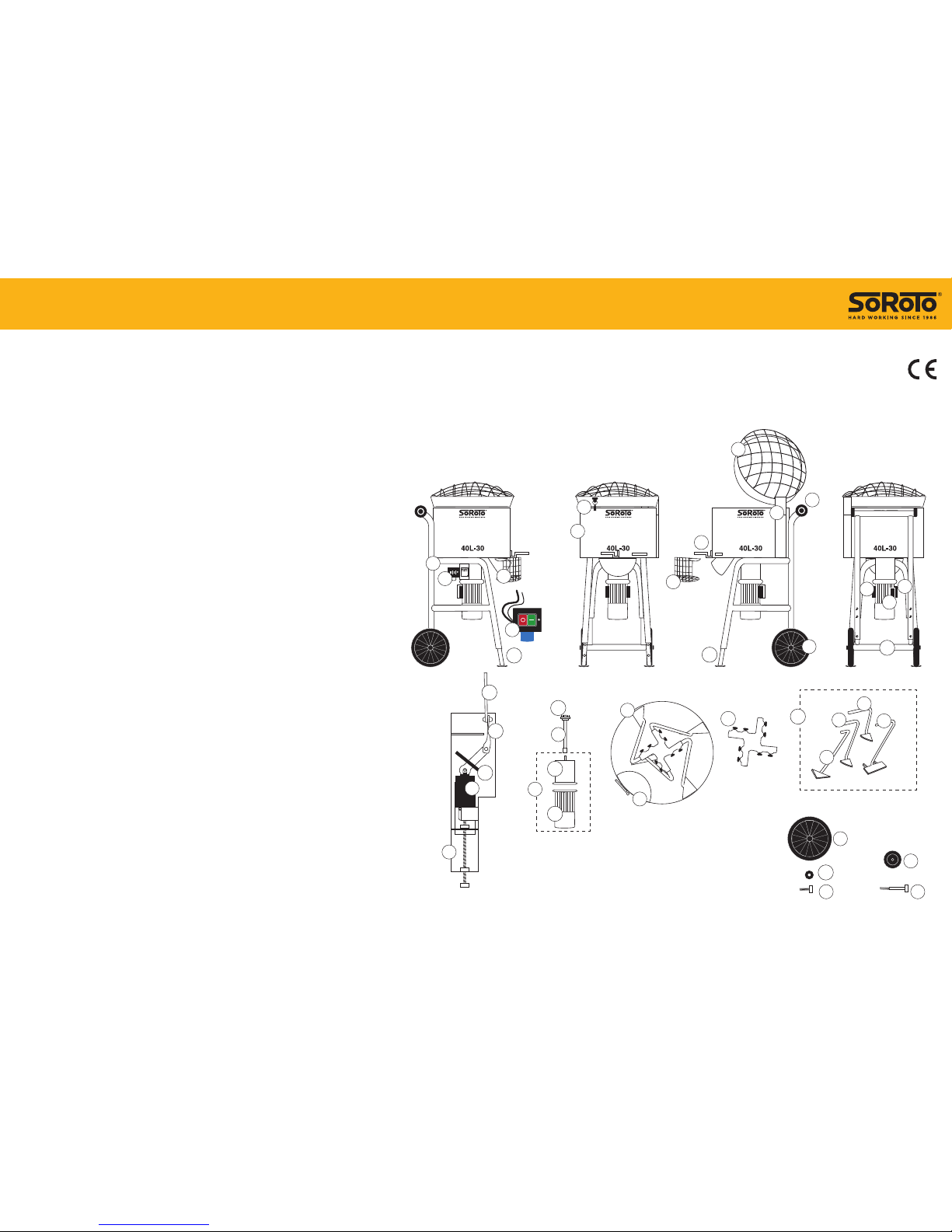
POS.NO. DESCRIPTION SPARE PART NO.
2 Grid lid (hinge 100 mm) ............................................................... 40.002
3 Mixer drum incl. mixer gate, complete set ............................ 40.003
3 R Rubber strap for grid lid .............................................................. 40.003R
4 Frame, complete w/wheels etc. ................................................ 40.004
4 A Frame, “Body” — excl. wheels and telescopic legs ........... 40.004B
5 Loading wheels (1 pc.), 80 mm, excl. bolt ............................. 40.005
5 B Bolt (1 pc.) for 80 mm loading wheel ..................................... 40.005B
6 Wheel (1 pc.), 200 mm, excl. bolt ............................................. 40.006
6 B Bolt (1 pc.) for 200 mm wheel ................................................... 40.006B
6 W Washer (1 pc.) for 200 mm wheel ............................................ 40.006W
7 Mixer gate incl. bolt ....................................................................... 40.007
8 Switch 9.5 Amp. w/thermal circuit breaker ......................... 40.008
8 E Safety switch — by the grid lid .................................................. 40.008E
8 K Cassette for safety switch, complete ...................................... 40.008K
8 K1 Piece for safety switch, bended metal part.......................... 40.008K1
8 K2 Piece for safety switch, twisted metal part. ......................... 40.008K2
8 K3 Piece for safety switch, rubber part ........................................ 40.008K3
9 Mixer arm (1 pc.), Side (long) ..................................................... 40.009
9 A Mixer arm (1 pc.), Side (short) ................................................... 40.009A
10 Mixer arm (1 pc.), Side-base ....................................................... 40.010
11 Mixer arm (1 pc.), Rake ................................................................. 40.011
12 Drive shaft, complete .................................................................... 40.012
12 A Spring pins, complete set of 4 pcs. incl. a jig ...................... 40.012A
13 Gear motor 0.75 kW, 30 RPM, 230V ....................................... 40.013
13 G - Gear only ......................................................................................... 40.013G
13 M - Motor only ...................................................................................... 40.013M
14 Starting capacitor 125 µF ............................................................. 40.014
15 Operating capacitor 25 µF .......................................................... 40.015
16 Phase capacitor 20 µF .................................................................. 40.016
17 B Telescopic leg (1 pc.), rear ........................................................... 40.017B
17 L Telescopic leg (1 pc.), front — left side ................................... 40.017L
17 R Telescopic leg (1 pc.), front — right side ................................ 40.017R
17 SB Bolt and nut (1 set) for telescopic leg (1 pc.) ....................... 40.017SB
19 Safety grid — by the mixer gate ............................................... 40.019
22 Mixer arms, 4 pcs., complete set .............................................. 40.022
22 A Mixer arms, 4 pcs., wo/cross joint ............................................ 40.022A
30 Discharge chute (incl. nuts) ........................................................ 40.030
44 Cross joint for mixer arms, steel ............................................... 40.044
3R
2
5
3
7
7
8
8
4
9
9A
6
6
5
6B 5B
10
11
12
44
8E
8E
8K
22
19
15
16
30
14
13
13M
17R 17L
13G
22A
17B
6W
8K3
8K2
8K1
12A
SPARE PART LIST - 40L, 230V
GB-28.11..18
Spare Part List for the 40 L mixers, 110V, is available online at
www.soroto.com
This manual suits for next models
3
Table of contents


