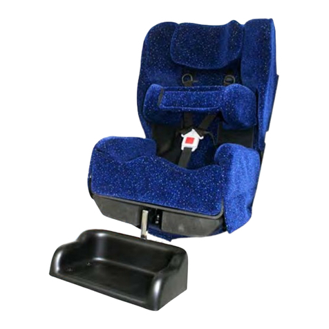
SOS P POD User manual

USER’S MANUAL
ALL USER’S OF THE EQUIPMENT SHOULD BE AWARE
OF THIS DOCUMENTAND ITS CONTENT
ISSUE 8
‘P’ POD
SEATING SYSTEM
|CLASS 1 & CUSTOM MADE DEVICE

1
Index
CONTENTS PAGE
Index 1
Safety Notes & Maintenance 1
Introduction 2
1. Assembling the ‘P’ Pod 3
2. Positioning the Client in the ‘P’ Pod 4
3. Cleaning the ‘P’ Pod 5 & 6
4. Optional Flip Over Headrest 6
5. Optional ‘P’ Pod Mobile Base 7
6. Optional Free Standing Tray 8
7. Optional Foot Support 9 & 10
8. Optional Bean Lap Tray 10
9. Optional Activity Frame 11
If You Detect a Fault or Breakage 12
SPECIFICATIONS 13 & 14
CONTACT DETAILS Backpage
SAFETY NOTES FOR USE
Make• sure the seat is securely fastened to the pod before use.
Make
• surethepelvicstrapandharnesses(iftted)aresecuredaroundtheclientwhen
in use.
NEVER
• leavethe‘P’Podclosetoanynakedame(i.e.opengasre).
NEVER
• removethepolystyreneballsfromtheirsealedbag.
NEVER
• leave anyone unattended in the ‘P’ Pod.
Make
• surethe‘P’Podtomobilebaseretainingstrapsaresecuredinplacewhenusing
the‘P’Podwiththeoptional‘P’PodMobileBase.
MAINTENANCE
Once• aweekremovethePod&BolsterfromtheBeanBagandgivethebagagood
shaketoagitatetheballscontainedinsidetomaintaintheirvolumeandshape.
Periodically
• checkforwear&tearonthecoversetcandthatthebagcontainingthe
ballsisnotsplitordamagedallowingthemtospillout(seesafetynotesabove).
Pay
• particularattentiontotheSeatPodtomakesurethisisstillingoodcondition.

‘P’ POD
(Class 1 & Custom Made Device)
Introduction
This• Users Guide for the ‘P’ Pod is designed to give guidance on its use and
maintenance.
The
• ‘P’Podgivesoverallposturalsupportsotheclientsweightisevenlydistributed
overalargearea.Thisimprovescomfortandrelaxation.
It
• isrecommendedthattheamountoftimeaclientsitsinthe‘P’Podiscontrolled,this
shouldnotexceedmorethan3hoursatatime.
Removing
• theclientfromthe‘P’Podisadvisedaftersuchaperiodtoofferachange
ofposture.Bydoingthisyouwillimproveaclientstolerancetosittinginthe‘P’Podon
a daily basis.
Under
• no circumstances leave anyone unattended when in the ‘P’ Pod.
There are 2 types of P Pod, Standard and Custom moulded.
Standard Sized ‘P’ Pods (Symmetrical)
Standard• ‘P’ Pod seats are available in different sizes and can be used for various
clientswhosedimensionsfallwithinthissizerange.
It
• isalwaysrecommendedthatassessmentsforstandard‘P’Podsaredonewitha
qualiedtherapistinattendanceifpossible.
Customised
The• CustomMoulded‘P’Podiscustommadetosuitanindividualclient’spostural
requirements.
This
• willrequireanassessmentbyoneofourqualiedseatingspecialists.
It
• isalwaysrecommendedthatassessmentsforCustomMoulded‘P’Podsaredone
withaqualiedtherapistinattendanceifpossible.
Each
• MouldedPosturalSeatismanufacturedforaparticularindividualandmustnot
beusedtoseatanyoneelse.
2

1. ASSEMBLING THE ‘P’ POD
3
Pod
Bean
Bag
Bolster
Support
Fig.1a
Fig.1c Fig.1d
Fig.1b
TheSOS‘P’Podcomesinthreebasic•
parts,thePod(seatsupport),Bolster
SupportandBeanBag(Fig.1a).
Firstly
• attach the Bolster Support to the
BeanBag,matinguptheVelcroonboth
parts or straight to bag depending upon
material(Fig.1b).
Place
• the Pod in place aligning the
frontstrapwiththeVelcro(iftted)on
theBeanBag(Fig.1c).Secureallxing
strapsinplaceonthePod(Fig.1c&1d).
Having
• assembledthe‘P’Pod,setitina
reclined position prior to placing the client
(Fig.2c).
Note:
• VelcroisonlyttedtoPodwhen
somematerialsareusedthatdonot
require it.

4
2. POSITIONING THE CLIENT IN THE ‘P’ POD
It• isrecommendedthatclientsover20kgarehoistedintothe‘P’Podequipment.
Manually lifting the client is not recommended.
It
• isimportantthatallcarersareawareofthe
Health & Safety guidelines for ‘Liftingand
Handling’.
ALL
• ‘P’PodsarettedwithaVelcroFastening
Pelvic Band. Before placing the client in the Seat
PodmakesurethatthePelvicBandispositioned
outsideoftheseatasthiswillbedifcultto
retrieveiftheclientsitsontopofit(Fig.1c).
Once
• the client is in the Seat Pod then secure
theminplacewiththePelvicBand.(Fig.2a)The
PelvicBandshouldbefastenedrmlyaroundthe
client.
IMPORTANT:
• Client’sshouldalwayshavethe
PelvicBandfastenedwhenseatedinthe‘P’
Pod.
When
• usingthehoist,makesurethatyoufollow
the hoistmanufacturer’sinstructions regarding
correct use.
On
• loweringtheclientintothe‘P’Podmakesure
that the client’s hips / pelvis are located as far
back as possible into the seat base and that the
‘P’Podissetinareclinedposition(Fig.2b).
It
• maybedecidedattheassessmenttot
additional client strap’s to the ‘P’ Pod to assist
withposturalcontrolifthisisthecasethensuch
additionalstraps,harnessesneedtobeinplace
whentheclientisseatedinthe‘P’Pod(e.g.Groin
StrapFig.2c).
Adjustments
• to the position of the seat support on
thebeanbagcanbedonebysimplyholdingthe
seatsupportandmovingitintoadifferentposition.
Please
• note, care and attention needs to be
taken when placing a client into the ‘P’ Pod as
it is very important that the client is correctly
positioned to give maximum comfort and
support.
Fig.2a
Fig.2c
Fig.2b

3.1 CLEANING THE ‘P’ POD SEAT
During• usethe‘P’Podseatwillrequirecleaning.
The
• SeatPodcovercanbeeasilyremovedbystretchingoffthepodandpassingthe
pelvicbandthroughtheslots.WiththeSeatPodcoverremovedtheinsidesurface
oftheSeatPodcanbeeasilycleanedusingmilddetergents.The Seat Pod is
manufactured from closed cell foam and is inherently waterproof.
If
• theSeatPodremainsslightlydampaftercleaningsimplyleaveforashortperiodat
roomtemperaturetodry.
DO
• NOT PUT THE SEAT NEXT TO A HOT FIRE OR USE EXCESSIVE HEAT TO
DRY AS THE SEAT POD IS THERMOPLASTIC AND COULD BE DAMAGED BY
EXCESSIVE HEAT THAT COULD AFFECT THE SHAPE OF THE SEAT.
DO
• NOT USE SCOURERS OR CAUSTIC SUBSTANCES SUCH AS BLEACH TO
CLEAN ANY PART OF THE P POD.
3.2 CLEANING THE COVERS
For• cleaningofremovablecoverspleaserefertowashlabelontheinsideofthe
padded covers.
T
• oremovetheSeatPodCoversimplystretchoff
the Seat.
Before
• launderingtheSeatPodCover,foldback
thevelcroretainingpads(Fig.3.2a)toprevent
themfromdamagingthecovermaterial.
To
• removetheFlipOverHeadrestCover:unzip
thecoverandremovetheinnerfoam.DO NOT
try and wash the inner foam as it is sealed in
a special membrane that cannot be removed
under any circumstances, to clean the foam
simply wipe down the plastic membrane.
For
• theBolster,PodandFootSupport:unzipthe
coverandremovethebagofpolystyreneballs
(Fig.3.2b).
Whe
• n placing the cover back on the Seat
Pod after cleaning note that the inner label is
positioned at the top of the seat to ensure correct
alignmentofthestrapsandgeneraltintothe
Seat.
ANY
• DEVIATIONS FROM THE ABOVE MAY
AFFECT THE FIRE RETARDANCY OF THE
COVER(S).
5
Fig.3.2b
Fig.3.2a

3.3. FIRE RETARDANCY
Fire• retardantmaterialshavebeenusedintheconstructionofthisseatingsystem.
It• isimportantthatnoaccelerantsareintroducedtothematerials(e.g.Hairspray,fabric
cleaners,deodorants,polishetc..),asthismayadverselyaffectthereretardancyof
yourequipment.
4. USING THE OPTIONAL FLIP OVER HEADREST
The• FlipOverHeadrestishungoverthebackofthe‘P’Podwhennotinuseand
placed into position to offer a change of head position if required.
To
• usetheheadrest,raisetheheadrestfromtherearofthe‘P’Pod(Fig.4a)andallow
torestinpositionasshown(Fig.4b).
If
• theheadrestistoolow/highthiscanbeadjustedbygraspingthestrapbucklesand
pulling/pushingthewebbingthroughthebuckles(Fig.4c)tolower/raisetheheadrest.
The
• headrestcanberemovedforwashingthecovers,etcbysqueezingtheside
releaseonthebuckles(Fig.4d)andpullingthetwohalvesofthebuckleapart.
Retting
• is a reversal of the above.
Fig.4a Fig.4b
Fig.4c Fig.4d
6

7
Fig.5b
5. USING THE OPTIONAL ‘P’ POD MOBILE BASE
Before• placingthe‘P’Podontothebasemake
sure that the Foot Brake is applied to the rear
wheels(Fig.5a).
It
• is ESSENTIAL that the client is removed
from the ‘P’ Pod before placing the ‘P’ Pod
onto the Mobile Base. This also applies when
the ‘P’ Pod is removed from the mobile base.
Place
• the ‘P’ Pod into the Mobile Base.
Pull
• thetworearstrapsoverthebackofthe
MobileBaseandsecuretheminplaceonthetwo
Velcropads(Fig.5b).
Removal
• is a reversal of the above.
To
• position the push handle at the rear of the
MobileBase,releasethetwolockingknobs(Fig.5c)thenrotatethepushhandleinto
positionandre-tightenthetwolockingknobs.
The
• clientcannowbepositionedinthe‘P’Pod(seepage4)andthebrakesreleased
ifrequiredformoving.
The
• Mobile Base is for Indoor use only and NOT TO BE USED outdoors.
The
• Mobile Base should NEVER be used with the client seated for transportation
in a moving vehicle.
Make
• sure the brake is applied whilst the Mobile Base is stationary.
NEVER• LEAVE ANY CLIENT UNATTENDED IN THE MOBILE BASE.
Fig.5a
Fig.5c

8
Fig.6cFig.6.1b
6.1 USING THE OPTIONAL FREE STANDING TRAY
With• theclientseatedinthe‘P’Pod,locatethe
feestandingtrayinfrontofthe‘P’Podasshown
(Fig.6.1a).
If
• the tray needs adjusting this can be raised/
loweredorangled.
To
• raise/lowerthetray,releasethetwolocking
knobs(Fig.6.1b)thensetthetraytothedesired
heightandre-tightenthetwolockingknobs.
To
• adjustthetraytopangle,releasethetwocap
bolts(Fig.6.1c)withanAllenkey(notprovided)
then set the tray to the desired angle and re-
tightenthetwocapbolts.
6.2 USING A TRAY WHEN USING THE MOBILE BASE
When• usingthe‘P’Podonamobilebaseunitthe
unitwillhavestandardlocationsfortheuseofa
tray.
T
• hetrayislocatedintotheMobilebaseviatwo
socketsatthesideandlockedinplacewiththe
lockingknobs‘A’(Fig.6.2a).
The
• height of the foot tray can be altered by
releasingthelockingcollar“B’withanAllen
key(notprovided)andthelockingknobs‘C’
(Fig.6.2a)andraising/loweringintoplace.Lock
knobsandlockingcollarswhennished.
Fig.6.1a
Fig.6.2a
B
CA

9
7.1 USING THE OPTIONAL FOOT SUPPORT
Remove• thePod&BolsterfromtheBeanBag.
LaythetwostrapsontopoftheBeanBag
(Fig.7.1a)andattachthevelcrototherearofthe
BeanBag(Fig.7.1b).
Ret
• thePod&Bolster(seepage3)totheBean
BagandclipthetwostrapsontheFootSupport
tothetwostrapsontheBeanBagviathebuckles
(Fig.7.1c).
Correctly
• ttedFootSupportasshown(Fig.7.1d).
Adjustment
• of the height of the Foot Support is
done by grasping the buckle and pulling the top
ofthestrapsthroughthebuckles(toraise)orthe
bottomofthestraps(tolower)(Fig.7.1e).
Removal
• oftheFootsupportisviathetwoclips
(Fig.7.1c).
Fig.7.1b
Fig.7.1d
Fig.7.1a
Fig.7.1c
Fig.7.1e

10
8. USING THE OPTIONAL BEAN LAP TRAY
With• theclientinthe‘P’Pod,placethetrayon
theirlap(Fig.8a)makingsurethebeanbagis
underneath the tray top.
Lift
• upthetworearseatstrapsfromthe‘P’Pod
andattachthelaptraystrapsontothesetwo
Velcropads(Fig.8b),ttheseatstrapsinplace
on top of the tray straps.
Correctly
• ttedtray(Fig.8c),removalisa
reversaloftheabove,butmakesuretheseat
strapsarerettedtothe‘P’Pod.
The
• beanbagcanberemovedfromthetray,and
thecoverremovedforcleaning.
Fig.8a
Fig.8b Fig.8c
7.2 USING A FOOT SUPPORT WHEN USING A MOBILE BASE
When• usingthePPodinamobile
BaseUnit,theunitwillhaveaxed
location for a foot support.
T
• he foot support is located into the
Mobilebaseviatwosocketsatthe
frontandlockedinplacewiththe
lockingknobs‘A’(Fig.7.2a).
The
• height of the foot support can
be altered by releasing locking
knobs‘B’(Fig.7.2a)andraising/
loweringintoplace.Lockknobs
whennished.
The
• depth of the foot support can be
altered by releasing locking knobs
‘C’(Fig.7.2a)andslidingforward/backwardsintoplace.Lockknobswhennished.
Fig.7.2a
B
A
C

11
9. USING THE OPTIONAL ACTIVITY FRAME
Remove• theframefromthebag(ifsupplied),placethebaseframeontheoorwith
thefeetfacingdownandthetwo‘T’barsintheuprightposition(Fig.9a).
Slide
• thetopframeintothetwo‘T’barsandtighteninplacewiththetwowingknobs
(Fig.9b).
Position
• theActivityFrameastridethePPodandmoveuntilthepreferredpositionas
in Fig.9c.
The
• heightoftheframecanbeadjustedviathetwowingknobs(Fig.9b)andthedepth
by sliding the ‘T’ bars along the base legs.
The
• stopsonthetopframeloopcanberepositionedbyunscrewingthehook(Fig.9d)
andmovingalongtheframeuntildesiredpositionisachieved,thenre-tightening the
hook.Thestopsareusedforlocatingstimulatingobjectsthatcanbehungfromthetop
loop.
Fig.9a Fig.9b
Fig.9c Fig.9d
Feet
‘T’ Bar

12
IF YOU DETECT A FAULT OR BREAKAGE
IF YOU DETECT A FAULT OR BREAKAGE OF THE EQUIPMENT THEN REPORT1. THIS IMMEDIATELY.
UNDER2. NO CIRCUMSTANCES ARE ANY MODIFICATIONS / ALTERATIONS TO BE
DONE BY ANYONE OTHER THAN SPECIALISED ORTHOTIC SERVICES LTD (see
contact details enclosed).
TO3. CONTACT SPECIALISED ORTHOTIC SERVICES LTD PLEASE REFER TO THE
INFORMATION INCLUDED IN THIS USER MANUAL.
REPAIRS & SERVICE
Within the warranty period.
AllSeatingSystemsmanufacturedbySpecialisedOrthoticServicesLtd.carryaguarantee
onthemainpartsfor12months,excludingcoversandstrapswhichareguaranteedfor
3months,whenusednormally.Ifduringthisperiodtheproductbecomesdefectiveand
needsrepairthenpleasecontactSOS(pleaseseetheendofthisusersguidefordetails).
Youcanalsocontactyourlocalwheelchairserviceregardinganyfaultsrequiringattention.
Outside the warranty period.
Foranygoodsrequiringrepairorattentionaftertheguaranteedperiod,thenassessment
canbemadeastothecostoftheworkrequiredtoeffecttherepair.
Onacceptanceofthisquotationtheworkwillproceed.
Misuse or neglect.
The repairs necessary resulting from misuse or neglect, whether within the warranty
period or not will be charged for.
MEDICAL DEVICES DIRECTIVE 93 / 42 EEC
Specialised Orthotic Services Ltd.incompliancewiththeMedicalDevicesDirective
have an obligation to investigate and take corrective action on defective devices. To assist
uswiththisprocedurewewouldappreciateyourassistanceinmeetingthisobligationby
informingusassoonaspossibleandmakethedeviceavailableforinspectionassoonas
possiblehavingbecomeawareofadefect.
WearerequiredtonotifytheCompetentAuthorityofcertaintypesofincidentswithin10to
30 days.
Aspartofourqualitysystemwehaveestablishedprocedurestodealwithsuchincidences
andwouldappreciateyourswiftnoticationtousviaourtelephone,faxore-maildetailsat
theendofthisusersmanual.

13
SYMMETRICAL ‘P’ POD DIMENSIONS in mm
‘P’ Pod size Micro 1 2 2½ 3 3½ 4 4½ 5 5½ 6
Hip Width 180 220 250 260 260 270 310 310 360 370 420
Trunk Width 160 190 220 240 250 240 270 270 320 330 340
PSD 120 210 230 260 290 290 330 350 350 420 430
Axilla Height 140 220 260 260 290 290 320 330 380 360 420
Shoulder Height 230 340 370 400 420 440 440 470 510 540 550
Head Height 360 430 500 560 560 620 620 660 660 700 730
(H)Front
Wheel Track
(J)Rear
Wheel Track
(F)MinWheelbase
(G)MaxWheelbase
(C)OverallHeight
(B)OverallWidth
(E)
(D)
(K)TurningRadius
(A)OverallLength
‘P’ POD MOBILE BASE DIMENSIONS in mm
SIZE A B C D E F G H J K
Small 1030 580 1060 550 150 490 560 385 450 675
Medium 1120 680 1070 650 150 590 660 425 480 780
Large 1225 680 1070 650 150 590 660 425 480 860
Ex Large 1325 680 1070 650 150 690 760 425 480 960
SPECIFICATIONS
‘P’ POD LAP TRAY SIZES DIMENSIONS in mm
SIZE A B
Micro 473 310
Small 523 390
Medium 618 443
(B)TrayDepth
(A)TrayWidth

14
SPECIFICATIONS (Cont.)
‘P’ POD TRAY SIZES DIMENSIONS in mm
SIZE A B C
Small 460 - 575 525 545
Medium 310 - 810 635 595
Large 760 - 1000 740 695
‘P’ POD ACTIVITY FRAME SIZES DIMENSIONS in mm
SIZE A B C D
Small 790 - 1120 770 980 400 - 880
Medium 1170 - 1500 770 980 400 - 880
(C)TrayDepth
(C)OverallLength
(D)Depth
(A)OverallHeight
(A)OverallHeight
(B)TrayWidth
(B)OverallWidth

I/D LABEL
Units 127/128, Fauld Industrial Park, Tutbury, Staffordshire. DE13 9HS
Tel: 0044 (0)1283 520400 Fax: 0044 (0)1283 520401
E-mail: [email protected]
Web: www.specialisedorthoticservices.co.uk
If you require further copies of this handout or require further details relating to any of its
content,thenpleasecontactus(Copyrightapplies):
Table of contents
Other SOS Indoor Furnishing manuals
Popular Indoor Furnishing manuals by other brands
Furniture of America
Furniture of America Ribeira CM7252CK Assembly instructions

CHITA
CHITA DC71266 Assembly manual

Kvik
Kvik PO841 manual

eliving FURNITURE
eliving FURNITURE NOBU Series Assembly instructions

Rauch
Rauch MD982 Assembly Instructions, Customer information

GrainWood
GrainWood Brushed Walnut MC1605 Assembly instructions

Easy Track
Easy Track RV2072 Assembly instructions

Argos
Argos Arizona 541/9517 Assembly instructions

J.Burrows
J.Burrows STILFORD 2M RECEPTION COUNTER 3CN Assembly instructions

Argos
Argos 2 Door Robe Assembly instructions

Frama
Frama SHELF LIBRARY Assembly guide

Ditalia Móveis
Ditalia Móveis DIT MP-320 Assembly manual