Sound Performance Lab TransientDesigner 9842 User manual

Model 9842
Manual
DynamicEffectProcessor
Transient
Designer

R&D:RubernTilgner
WrittenbyHermannGierandPaulWhite
Version3.1- 6/2005
The information in this document has been
carefullyverified and is assumed tobe correct.
However Sound Performance Lab (SPL)
reserves the right to modify the product
described in this manual at any time.Changes
without notice.This document is the property
of SPL and may not be copied or reproduced
in any manner, in part or full without the
authorisationof SPL.
LimitationsofLiability:
In no event will SPL be liable for any damages,
includingloss ofdata,lost profits,costof cover
or other special, incidental, consequential or
indirect damages arising from the use of the
unit, however caused and on any theory of
liability.This limitation will apply even if SPL or
an authorised dealer has been advised of the
possibility of suchdamage.
SoundPerformanceLab
P.O.Box1227
D-41368Niederkrüchten,Germany
Tel+49-2163-98340
Fax +49-2163-983420
E-Mail:info@soundperformancelab.com
www.soundperformancelab.com
©2000SPLelectronicsGmbH.Allrightsreserved.
Transient Designer
Model 9842
Manual

Transient Designer
3
Contents
Dearcustomer,
Thank you for the confidence you have shown towards SPL elec-
tronics GmbH by purchasing the SPL TRANSIENT DESIGNER, a highly
innovative Dynamic Processor manufactured to a high standard.
As you would expect from an SPL unit, the TRANSIENT DESIGNER
combinesexemplary technicalspecifications withintuitive usabi-
lity and unrivalled audio performance.Even though the TRANSIENT
DESIGNER is very simple to use, please read this manual through
carefully at least once to ensure you have all the information you
needtoget thebestout ofyournewpurchase.
Wewishyoueverysuccess withyournew TRANSIENT DESIGNER.
Your Sound Performance Lab-Team
I would like to start with my thanks to all our staff, particularly
RubenTilgner,whocreatedtheTRANSIENT DESIGNER.Theimportance
of their exceptional qualification and talents cannot be overesti-
mated.
Our products are often tested and compared in many publica-
tions, as well as by our customers themselves, and constantly
attract praise for the high standard of audio performance they
achieve.I would like to pass on this broad appreciation to those,
whodeserveit- myexcellentcolleagues.
Hermann Gier
Foreword
Thanks
Foreword ...................................................................................................... 3
Thanks ........................................................................................................... 3
Introduction................................................................................................. 4
OperationSafety......................................................................................... 5
Connections ................................................................................................ 6
TechTalk ....................................................................................................... 7
DifferentialEnvelopeTechnology®....................................................... 7
Theattackcontrol-circuitry..................................................................... 7
Thesustaincontrol-circuitry................................................................... 7
Connectionto digital systems ............................................................... 8
Control Elements .............. ACTIVE .....................................................10
.... SIGNALLED (Sig.LED)..........................10
... ATTACK ....................................................10
.. SUSTAIN ...................................................11
. LINK ..........................................................11
Applications ....................... Connections ..........................................12
...... Drums&Percussion .............................13
..... Guitar&Bass ..........................................14
.... Backings ..................................................14
... Keyboard,Sampler ...............................14
.. MoviePostPro ......................................14
. Mastering? ..............................................14
PowerSupply...............................................................................................15
Specifications ..............................................................................................16
Warranty........................................................................................................17

Transient Designer
4
The new TRANSIENT DESIGNER provides a revolutionary concept for
dynamic processing rendering controls such as Threshold, Ratio
and Gain superfluous. The TRANSIENT DESIGNER's automation is
highly developed, so that while the processing going on inside
the box may be very complex,the user has to deal with just a few
intuitive controls.SPL's Differential Envelope Technology® is the
first solution for level-independent processing of envelopes allo-
wing transients to be accelerated or slowed down and sustain
prolonged or shortened. The degree of dynamic processing
required to do this couldn't be duplicated even using a chain of
several conventional compressors, yet only two controls per
channel are required to allow the user to completely reshape the
attackandsustain characteristicsof asound.
Attack can be amplified or attenuated by up to 15dB while
Sustain can be amplified or attenuated by up to 24dB, enabling
weak drum sounds to be made much more percussive and
powerful,or for over-percussive transients to be softened.All the
necessary time-constants (Attack, Decay and Release) are auto-
mated and optimised adaptively in a musical manner according
to the characteristics of the input signal. This results in natural
soundingsignalprocessing andfastoperation.
The TRANSIENT DESIGNER uses envelope followers to track the
curve of the natural signal so that optimum results are guaran-
teed regardless of the input signal's dynamics. Because of the
level-independent processing inherent in Differential Envelope
Technology®, manual threshold adjustments are not required.In
order to maintain the cleanest possible signal path,the TRANSIENT
DESIGNER usesthe excellentlyspecifiedTHAT 2181-VCAs,whichare
especially natural sounding, transparent and create minimal
distortion. High amplitudes are processed without damping of
highfrequenciesor reducingbass.
For stereo operation the LINK function connects channel pairs
(1,2 and/or 3,4) such that both channels are controlled by the
same side-chain voltage so as to maintain a coherent and stable
stereo image. When operating in LINK-mode, the control
elements of the first (or third) channel, including the ACTIVE
switch,control the second (or fourth) channel, too.Each channel
is equipped with a relay hard bypass circuit to ensure a minimum
signalpathwhen theprocessis bypassed.
TheSignal-LEDs provideasimple and positivemeans to quickly
monitor the signal flow,which is particularly important if the four
channelsareconnectedtoa patchbay.
The TRANSIENT DESIGNER is a
revolutionary Dynamic
Processor based on level-
independent sound proces-
sing that makes it possible to
radically change the attack
and sustain characteristics of
any musical sound in a crea-
tive way.
Transients can be accelerated
or slowed down and sustain
may be prolonged or shor-
tened.
This is made possible by the
use of adaptively optimised
time-constant parameters.
SPL's Differential Envelope
Technology® for level-inde-
pendent processing.
The latest VCA-technology
preserves audio transparency
and minimises distortion.
There are four independent
channels of signal processing
in the TRANSIENT DESIGNER,
though channels may also be
linked for stereo operation.
The unit features a relay hard
bypass and Signal-LEDs to
simplify metering.
Introduction

Transient Designer
5
Packaged in a standard 19" EIA format and occupying 1U
(44,45mm)of rackspace,the TRANSIENT DESIGNER canbe installedin
astandardrack,butitisrecommendedthattherearofthecasebe
supported, especially in touring applications. The TRANSIENT
DESIGNER should not be installed near units which produce strong
magnetic fields or extreme heat. Do not install the TRANSIENT
DESIGNER directly above or below power amplifiers or digital
processors.If possible,the TRANSIENT DESIGNER should be placed in
an 'analogue rack' where the majority (or all) of the equipment
installed is analogue. Check that the voltage details quoted on
thebackpanelare the sameasyourlocalmains electricitysupply.
• Useasmall,flat bladedscrewdrivertosetthevoltageselectorto
thevoltageforthearea inwhich the unitwill beused.
• Nevercoverup theventilationslotson thetopside ofthe unit.
• If, during operation, the sound is interrupted or indicators no
longer illuminate,or if abnormal odour or smoke is detected,or
if liquids are spilled on the unit, immediately disconnect the
powercordplugandcontactyourdealer.
• Only clean your TRANSIENT DESIGNER with a soft,lint-free cloth.Use
only standard cleaning agents. Never use alcohol or paint
thinner,because theymaydamage the finish.
Important security advices
Operation Safety

Transient Designer
6
Before connecting the TRANSIENT DESIGNER switch power off at all
connectedunits.
TheTRANSIENT DESIGNER isfittedwithXLR-connectorsforbalanced
operation.Thefollowingillustrationshowsthepin-wiring:
Toensureoptimalsignalquality,SPLhasdevelopedanewhybrid-
component balanced input/output stage using all laser-trimmed
resistors with a tolerance of 0.01%.This approach has resulted in
an exceptionally high CCMR (common mode rejection);-80dB at
1kHzand-75dBat10kHz.
Should the need arise to use the XLR connectors in an unba-
lanced system,pin 3 of the XLRs should be grounded. The follo-
wing illustration shows how to properly unbalance a balanced
signal:
Rear panel TRANSIENT DESIGNER,model 9842
Connections
21
3
12
3
Pin wiring: XLR output
1 = GND, 2 = hot (+), 3 = cold (-)
Pin wiring: XLR input
1 = GND, 2 = hot (+), 3 = cold (-)
soundperformancelab.com
TO REDUCE RISK OF FIRE
OR ELECTRIC SHOCK DO
NOT EXPOSE THIS UNIT
TO RAIN OR MOISTURE.
DISCONNECT MAINS
BEFORE REMOVING COVER.
VOLTAGE/FUSE
XLR Wiring: 1 = GND/ 2 = (+)/ 3 = (–)
Output 4Input 4Output 3Input 3Output 2Input 2Output 1Input 1
GND LIFT
AVIS: RISQUE DE CHOC ÉLECTRIQUE - NE PAS OUVRIR
RISK OF ELECTRIC SHOCK
DO NOT OPEN
CAUTION
Serial #
WARNING
Sound Performance Lab
SPL electronics GmbH
41372 Niederkrüchten
Germany
Made in Germany
230 V
50 Hz
Fuse:
200mA
115 V
60 Hz
Fuse:
400mA
230 V
Input 4Output 4Input 3Output 3Input 2Output 2Input 1Output 1
Transient Designer
7
SPL's Differential Envelope
Technology® realises level-
independent envelope
processing,so doing away
with the need for a conven-
tionalThreshold control.
Two envelopes are generated
and compared - theVCA
control voltage is derived
from their difference.
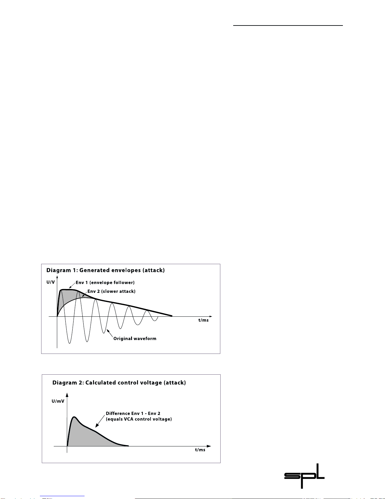
Diagram1
illustrates the original curve
and both generated enve-
lopes for processing the
attack period.The envelope
follower Env 1 corresponds to
the shape of the original
curve.The attack of Env 2 is
lower.
Diagram 2
illustrates the difference from
Env 1 and Env 2,giving the
VCA control voltage.
In nearly every aspect the TRANSIENT DESIGNER is different from
conventional Dynamic Processors or Compressors. You don't
needtoknowhowtheTRANSIENT DESIGNER worksinordertobeable
to use it effectively,but if you're at all curious as to what goes on
insidethebox,readthis section whilereferringtothe diagrams.
Differential Envelope Technology®
Differential Envelope Technology® maintains identical envelope
processing from quiet to loud signals (from pianissimo to fortis-
simo) without the need for the user to adjust any external para-
meters. In a conventional system, low level signals would be
excluded from processing. Both parameters (ATTACK and
SUSTAIN)workinparallel anddonot influenceeachother.
The ATTACK control circuitry
The ATTACK control circuitry uses two envelope generators.The
first follows the shape of the original curve (Diagram1:envelope
follower Env 1), while the second generator produces the enve-
lopeEnv2(Diagram 1) witha slowerattack.
ThehatchedareashowsthedifferencebetweenEnv1andEnv2
(Diagram 2), and the VCA control voltage is derived from this
difference.PositiveATTACKvaluesemphasiseattackevents,nega-
tiveATTACKvaluessmoothoutthe attackenvelopesofevents.
Tech Talk

Transient Designer
8
The SUSTAIN control circuitry
The SUSTAIN control circuitry includes two further envelope
generators. The envelope follower Env 3 (Diagram 4), again
followstheshapeof the originalcurve.
For a longer period the envelope generator Env 4 (Diagram 4)
holds the sustain level according to the peak level and the VCA
control voltage is generated by the difference between Env 3
(Diagram4)and Env4(Diagram5:hatched area).
The sustain is extended at positive settings and shortened at
negativesettings.
Diagram 3
illustrates the shapes of the
processed curves with
maximum and minimum
attack,compared to the
original curve from
Diagram 1.
Diagram 4
illustrates the original curve
and both envelopes generated
for processing the sustain
period.The envelope follower
Env 3 corresponds to the
original curve.The sustain of
Env 2 is extended.
Diagram 5
illustrates the difference
between Env 4 and Env 3.It
determines the VCA control
voltage.
Tech Talk

Transient Designer
9
Diagram 6
illustrates the processed
curves with maximum and
minimum sustain compared
to the original curve from
Diagram 1.
Important advice when connecting to digital
recording systems:
Each unit connected to the TRANSIENT DESIGNER should be able to
handle high input levels. With maximum ATTACK values the
instantaneous input level can increase by up to +15dB. For this
reason it is recommended to connect the TRANSIENT DESIGNER to an
analogue mixing console,because these generally have enough
headroom to process peak levels of more than 15dB without
clipping.However,it is imperative to check the input levels of the
mixerandanyclipmonitor LEDsatthe channelinserts.
If the TRANSIENT DESIGNER is connected directly to a ProTools 888
interface,a Yamaha O2R mixer or similar units with internal A/D-
converter, ATTACK values of about +6dB may overload the
converters.In such cases reduce the Input Gain of these systems
to provide adequate headroom to accommodate the enhanced
transients.
Tech Talk
Prevent overload

Transient Designer
10
The ACTIVE switch operates a hard-bypass relay circuit to switch
the channels in and out of processing and a status LED indicates
thatthechannel isactive.
The unit also switches to relay hard-bypass automatically in the
caseof a powerfailure,either on the primary or secondary side of
the power supply, or when the unit is turned off at the POWER
switch.
If the TRANSIENT DESIGNER is operated in the LINK mode (see 5),
channel one's (or three's) ACTIVE also switches channel two (or
four) in and out. Note that channel two's ACTIVE status-LED will
alsofollowchannelone's ACTIVEstatus.
The SIGNAL-LED indicates an incoming signal with a level excee-
ding -40dB. In complex studio arrangements the LED indication
helpstocheck ifa signal actually arrivesat the TRANSIENT DESIGNER.
With the ATTACK control, the attack period of a signal can be
emphasised or attenuated by up to 15dB. For detailed informa-
tion about the mode of operation of the ATTACK control please
readthesection'TechTalk'onpages 7and8.
5
34
2
1
Control elements
Signal-LED 2
Active 1

Transient Designer
11
The ATTACK control circuitry incorporates two envelope genera-
tors.Onefollowstheoriginal curvewhilethe secondproduces an
envelopewith a slowerattackperiod (Diagram1,page 7).
The difference (Diagram 2, page 7) between these envelopes
results in a voltage that controls the VCA, boosting the transient
for a period equal to the duration of the original transient. The
amplitude of the attack is increased,if positive ATTACK values are
set, while negative ATTACK values reduce the level of the attack
transient. For detailed information about using the ATTACK
controlpleasereferto pages 12ff.
The SUSTAIN control increases or reduces the level of the sustain
portion of a signal by up to 24dB.For detailed information about
the mode of operation of the sustain control please read the
'TechTalk'section on pages8 and9.
Two envelope generators work in the SUSTAIN control circuitry,
too. Again an envelope follower pursues the original envelope
and adapts optimally to the curve of sustain.This second gene-
rator produces an envelope with extended sustain (Diagram 4,
page 8).The difference between both envelopes is then used to
calculate the voltage controlling the VCA, though as with the
ATTACKcircuitry,theenhancementceasesattheendofthesignal
beingprocessed.
Sustain amplitude is increased for positive SUSTAIN settings
andreducedfornegativesettings.Fordetailedinformationabout
usingthe SUSTAIN controlpleaserefertopages 12ff.
When processing stereo material, the LINK function should be
switched on so that the linked channels produce the same
degree of gain change, regardless of any difference in levels of
the two channels. This is necessary to maintain a coherent and
stablestereoimage.
The front panel controls,including the ACTIVE switch of channel
1or3,function asthe master controlsinLINK mode.
Control elements
Sustain
4
Attack
3
Link
5
Transient Designer
12
The TRANSIENT DESIGNER is ideally suited for use in professional
recording,inprojector home studiosand P.A.applications.
For the first time the TRANSIENT DESIGNER provides the technology
to manipulate the attack and sustain characteristics of a signal
regardless of level, and using simple controls. Usually equalisers
areusedtoseparateinstrumentsin amix–thetonalaspectofthe
signal is considered,but not the temporal aspect.By accelerating
thetransientsor/andshortening the sustainofaninstrument,the
mix can be made to sound more transparent.Instruments can be
mixed at lower levels,still maintaining their positions in the mix,
butoccupyingless space.
'Front/rear-positioning' of drums or other percussive instru-
mentscaneffectivelybe're-miked'duringthemix–atleast,that's
the subjective effect. Applied to single instruments or loops,this
technology creates new sounds or adds weight and authority to
existingsounds.
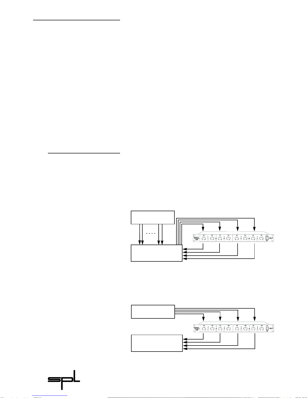
There are several ways to connect the TRANSIENT DESIGNER to your
equipment. One of the most flexible options is wiring the
TRANSIENT DESIGNER to a patchbay, and if your console has swit-
chable insert points to prevent audio running through the
patchbaywhennotrequired,somuch the better.
Alternatively, the TRANSIENT DESIGNER may be connected directly
tothechannel orsubgroupinserts.
The TRANSIENT DESIGNER may also be connected directly to the
outputstagesofdrummachinesorsamplers,ifnosuitableinserts
are available, though it should not be connected via an effects
auxsend/return loop.
Diagram 7
Connecting the TRANSIENT
DESIGNER to the channel inserts
of the mixer for processing
different tracks.
Diagram 8
Direct wiring between
sampler or drum machine
and mixer.
Channelor SubgroupInsert Sends
Channelor Subgroup InsertReturns
Multi-Track
Mixer
SamplerOutput
TRANSIENT DESIGNER OutputtoMixer
Sampler
Mixer
Applications
Connections

Transient Designer
13
One of the most interesting applications of the TRANSIENT
DESIGNER is processing drum and percussion sounds, both from
samplestolivedrum sets:
• The attack of a bass drum or a loop can be emphasised to
increasethepowerand presenceinthe mix.
• The sustain period of a snare or a reverb-flag can be shortened
inaverymusical waytoobtainmore transparency in themix.
• Recording a live drum set,toms or overheads can be shortened
withoutphysicallydampingthem.
• Miking live drums is considerably faster and easier,because the
apparent 'distance' of the microphone can be corrected by
varying the ATTACKandSUSTAINvalues.
• The TRANSIENT DESIGNER is a perfect partner to noise gates in live
drummiking.
• Corresponding adaptively to the duration of the original signal,
the sustain can be shortened more musically than with tightly
adjustedreleasetimes,effectively reducing crosstalk.
• When recording live drums or other instruments on a HD recor-
ding system, the TRANSIENT DESIGNER prevents time-consuming
removingofcrosstalksignals onthehard disk.
• It is possible to create unusual dynamic effects, including new
and interesting pan effects. If, for example, a mono loop is
patchedthrough twochannelsof theTRANSIENT DESIGNER panned
hard left and right in the mix, such that the left channel is
processed with increased ATTACK and reduced SUSTAIN while
the right channel is adjusted in the opposite way,a very special
stereo loop sound is created.You have to try this to appreciate
what it sounds like, but expect to hear a lot of unusual stereo
movement.
• By reducing ATTACK and increasing SUSTAIN, signals that are
too up-front sounding can be moved back into the mix.
AdditionallytheFXparts of'too dry' signalsare strengthened.
• Drum sounds are easier to integrate into the mix.If the acoustic
level of a snare is expanded to approximately +4dB by increa-
sing the attack value,the effective increase of peak levels in the
overallmix ismerelyabout 0.5dBto1dB.
Applications
Drums & Percussion

Transient Designer
14
• Usedtoprocessguitarsounds,theTRANSIENT DESIGNER softensthe
instrument by lowering the attack.Alternatively,increasing the
attack lets the sound jump to the front of the mix,which works
particularlywellforpickingguitars.
• Highly distorted electric guitars are already highly compressed,
leavingthemwithminimal dynamicrange.Thiscanobscurethe
note attacks,but increasing the attack setting clarifies the indi-
vidualnotes.
• High distortion also prolongs the sustain, broadening the
sound.Reducing theSUSTAINsetting counteractsthose effects.
• Increasing the sustain period of miked acoustic guitars
produces clearer audible stereophonic sounds. Reducing the
sustainvaluecanhelp dryupthe sound.
• When recording choirs, the effect of too much 'ambience' can
bereducedbyusing alowersustain setting.
• Frequently keyboard and sample sounds are intensively
compressed leaving little of their original dynamic range.
Increasing the attack brings back the natural dynamics so the
sounds need less space in the mix and are easier to pick out,
evenatlowerlevels.
• With the help of the TRANSIENT DESIGNER 'Budget' drum machines
can provide sounds and grooves that sound far more powerful
anddynamicthan theoriginal untreatedsounds.
• Effect sounds and sample libraries benefit from more punch
and more power – useful when working on TV commercials or
moviesoundtracks.
• 'Out door' recordings often suffer from poor microphone posi-
tioning.The TRANSIENT DESIGNER can help create the effect of re-
positioningthemics during the mix.
• However, like any good thing, you have to know where not to
use it.For example,use in mastering is not recommended as it's
rarely a good idea to treat a whole mix at once. Instead, treat
individualelementswithin themix.
Backings
Guitars
Keyboards, Sampler,
Drum-Machines
Movie Post Pro
Mastering?
Applications

Transient Designer
15
Internal 15 VA torroidal
transformer
Voltage selector
Ground-lift switch
Transformer,power cord and
mains connector with VDE,
UL and CSA approvals.
Fuses (primary voltages):
200 mA/400 mA.
Special care has gone into the design of the power supply of the
TRANSIENT DESIGNER.Thepowersupply is theheart ofany electronic
system,and the better it is,the better the whole system works.In
an audio system, this translates into better sound quality, lower
noiseandlower distortion.
Thepowersupplyisbasedarounda15VAtorroidaltransformer
andisdesignedwithoutan air gaptominimiseinducedhum and
noise.The primary voltage may be selected between 230V/50Hz
and 115V/60Hz by means of a recessed slide switch on the rear
panel and a ground-lift switch is fitted for use where ground
loops are causing hum problems.When the GND LIFT switch is set
tooff,thecircuit groundisisolated from thechassis ground.
The detachable power cord is a standard 3-wire type fitted
with an IEC mains connector; the transformer, power cord and
mainsconnectorhaveVDE,ULand CSAapprovals.Thefuses have
valuesof200mA/230V and400mA/115V.
On the secondary side of the power supply,an RC combination
isusedtofilteroutnoiseandhum.Both half-wavesaresmoothed
with2x1000µFcapacitorsinthepositiveand2 x1000µFcapaci-
torsinthenegativevoltagesupplypath,andbothlinesusepreci-
sionvoltageregulatorsforoptimumstability.Deviationsofonlya
fewmillivoltscanimpairaudioquality,introducingartefactssuch
as loss of stereo imaging or a diffuse sound character. Particular
care has gone into the circuit layout and component choice to
minimise crosstalk between the audio circuitry and control
voltages.
Power Supply

Transient Designer
16
Input & Output
Instrumentation amplifier, electronically balanced (differential),
transformerless
Nominal inputlevel ...................................... +6dB
Inputimpedance .......................................... = 22kOhms
Outputimpedance ...................................... <600Ohms
Max.input level.............................................. +24dBu
Max.output level .......................................... +22,4dBu
Minimum load ohms ................................... 600Ohms
RelayHardBypass/ PowerFailSafety
Measurements
Frequency response..................................... 20 Hz- 100 kHz
... (100 kHz= -3 dB)
CCMR(commonmoderejection)............. -87dBu @100 Hz
... -80dBu @1kHz
.. -75dBu @10kHz
. -70dBu @20kHz
THD&N ............................................................ 0,004% @1kHz
S/N CCIR468-3 .............................................. -89dBu
S/N A-weightened ....................................... -105dBu
Power Supply
Torroidaltransformer................................... 15VA
Fuses(230V/ 115V) .................................... 200mA /400mA
Ground-Liftswitch,Voltage selector
Dimensions
Housing............................................................ Standard EIA19"/1U,
... 482x44,45 x237mm
Weight .............................................................. 3,4 kg
Note: 0 dBu = 0.775 V.Subject to change without notice.
Specifications

Transient Designer
17
SPL electronics GmbH (hereafter called SPL) products are
warranted only in the country where purchased, through the
authorized SPL distributor in that country, against defects in
material or workmanship. The specific period of this limited
warranty shall be that which is described to the original retail
purchaser by the authorized SPL dealer or distributor at the time
ofpurchase.
SPL does not, however, warrant its products against any and all
defects:
1) arising out of materials or workmanship not provided or
furnishedbySPL,or
2) resulting from abnormal use of the product or use in violation
ofinstructions,or
3) in products repaired or serviced by other than authorized SPL
repairfacilities,or
4)inproductswith removedor defacedserial numbers,or
5) in components or parts or products expressly warranted by
anothermanufacturer.
SPL agrees, through the applicable authorized distributor, to
repair or replace defects covered by this limited warranty with
parts or products of original or improved design, at its option in
each respect,if the defective product is shipped prior to the end
ofthewarrantyperiodtothedesignatedauthorizedSPLwarranty
repair facility in the country where purchased, or to the SPL
factory in Germany, in the original packaging or a replacement
supplied by SPL, with all transportation costs and full insurance
paideachwayby the purchaseror owner.
All remedies and the measure of damages are limited to the
above services. It is possible that economic loss or injury to
person or property may result from the failure of the product;
however, even if SPL has been advised of this possibility, this
limited warranty does not cover any such consequential or inci-
dentaldamages.Some statesorcountries donot allowthe limita-
tions or exclusion of incidental or consequential damages,so the
abovelimitationmaynotapply to you.
Any and all warranties, expressed or implied, arising by law,
courseofdealing,courseofperformance,usageoftrade,orother-
wise,including but not limited to implied warranties of merchan-
tability and fitness for particular,are limited to a period of 1 (one)
year from either the date of manufacture. Some states or coun-
tries do not allow limitations on how long an implied warranty
lasts,sotheabovelimitationsmaynot applyto you.
This limited warranty gives you specific legal rights, and you
may also have other rights which vary from state to state,country
tocountry.
SPL electronics GmbH,D-41372 Niederkrüchten,Germany
Warranty
Table of contents
Other Sound Performance Lab Recording Equipment manuals


