Sound Technology TR9030GEN2 User manual

Instruction Manual Version 4.0
PORTABLE VETERINARY X-RAY EQUIPMENT
DIGITAL RADIOGRAPHY
SOUND TR9030GEN2

Sound Technologies, Inc
1.800.268.5354
soundvet.com
Contents
This manual provides installation, operation and maintenance instructions for the
SOUND TR9030GEN2 portable veterinary x-ray unit. Copy and transfer without notice
is prohibited. Operate the equipment correctly according to this instruction manual.

Sound Technologies, Inc
1.800.268.5354
soundvet.com
CONTENTS
1.0 NOTICE FOR SAFE OPERATION (3)
2.0 INTRODUCTION (5)
3.0 COMPONENTS (6)
4.0 MAIN PARTS (7)
5.0 CONTROL PANEL (8)
6.0 PRECAUTION IN USE (9)
7.0 OPERATING PROCEDURES (11)
8.0 WARNING INDICATION (16)
9.0 TROUBLESHOOTING (17)
10.0 DR INTERFACE CONNECTOR (18)
11.0 SPECIFICATION (20)
12.0 DUAL kV SYSTEM (22)
Contents
Sound Technologies, Inc
1.800.268.5354
soundvet.com
1.0 Notice for Safe Operation
1.0 NOTICE FOR SAFE OPERATION
1. The following safety symbols will be used in this manual.
WARNING: This symbol is warning about the possibility of injury of
patient or operator.
CAUTION: This symbol is caution for the possibility of product failure.
NOTE: This symbol is note for operating this product correctly.
WARNING:
RADIATION
HAZARD:
This symbol warns of a possible radiation hazard.
2. The SOUND TR9030GEN2 are not certied for human use.
3. During operation, the operator should be fully protected from exposure to radiation
and use a dosimeter badge.
4. The SOUND TR9030GEN2 have been developed specially for diagnostic veterinary x-ray
applications. It should not be used for other applications.
5. X-ray equipment should be operated only by individuals who have appropriate training and licenses.
WARNING: This x-ray unit may unit be dangerous to patient and operator unless
safe exposure factors and operating instructions are observed.
6. Please take the following precautions during installation:
A) Keep equipment dry.
B) Do not subject equipment to excessive atmospheric pressure, temperature, humidity,
direct sunlight, dust, or air containing salt and sulfur.
C) Do not subject equipment to excessive vibration and/or shock during transportation, etc.
D) Do not store equipment under any adverse gaseous conditions.
E) Insure that the input electrical voltage, amperage and hertz are correct and the unit is
properly grounded.
7.During operation, consult or develop a technique chart for appropriate anatomy, distance,
and screen/lm or digital imaging system speed.
Sound Technologies, Inc
1.800.268.5354
soundvet.com
8. After using the equipment:
A) Remove cords carefully, if necessary.
B) Keep equipment clean and dry.
C) Store inside carrying case in cool, dry environment.
9. Maintenance
For proper maintenance, this schedule must be followed:
A) Every 6 months
1) Check the alignment of the collimator light eld with the x-ray beam.
2) Check the audible and visible exposure functions.
3) Check to see that all bolts, screws and lock nuts are tight.
4) Re-adjust the position of laser beams to be aligned with the central ray
of the x-ray unit at the source-to image-distance (SID) you typically use.
1.0 Notice for Safe Operation
WARNING: TO INSTALLERS, SERVICE PERSONNEL, AND USERS OF X-RAY SYSTEMS RE
EQUIPMENT MOUNTING SECURITY. When performing periodic maintenance,
calibration, or changing of the components of an x-ray system, the person in
charge should conrm whether all components and screws are properly connected
and securely tightened. Continued use of loose components is dangerous and could
cause further loosening, damage of screws and bolts, or mount failure which could
result in HEAVY COMPONENTS FALLING DURING USE. The operator should report all
loose system components to x-ray service personnel for
immediate repair.
It is especially advised to check the security of the collimator mounting screws.
This can be accomplished easily by grasping the collimator and attempting to
move it in relation to the x-ray unit. The system should also be inspected for
loose joints, not only between the collimator and tube head/control, but other
mounting areas as well.

Sound Technologies, Inc
1.800.268.5354
soundvet.com
The SOUND TR9030GEN2 are a constant potential portable x-ray device utilizing the latest high
frequency inverter system. These x-ray units have the following features:
1. This x-ray unit is very easy to carry by hand because of its small size and lightweight.
2. Input line voltage of this x-ray unit is a wide range of 70VAC – 130VAC(120V model),
140VAC – 260VAC(230V model), 50/60Hz.
3. Dual Laser Pointers in the light beam collimator are easy to adjust to indicate the central ray
at your typical source-to-image distance (SID).
4. A high frequency inverter with output greater than conventional models and constant x-ray
tube voltage.
5. Output of kV and mA are corrected and stabilized by automatic feedback circuits.
6. Compared with conventional generators, the waveform can be more than 2.5 times as effective.
7. Focal spot size of x-ray tube is 0.8mm. Therefore, the quality of the resultant radiographs
is better than x-ray taken by units with larger focal spots.
8. It is easy to select either exposure time or mAs display on the control panel.
9. The last kV and timer settings before the unit is turned off are stored for the next operation.
10. Five different technique setting can be stored in memory for quick recall on this x-ray unit.
11. These models have an interface connector for DR digital imaging system.
WARNING: As the SOUND TR9030GEN2 use high voltage, please read this manual
carefully prior to operation.
2.0 INTRODUCTION
2.0 INTRODUCTION

Sound Technologies, Inc
1.800.268.5354
soundvet.com
3.0 COMPONENTS
3.0 COMPONENTS
1.0 X- ray Equipment 1 set
2.0 Hand-held Exposure Switch and Cord 1pc.
3.0 Spare Fuse 2pc.
4.0 Instructional Manual 1pc.
5.0 Power Cord 1pc.
6.0 Warranty Sheet 1pc.
6.0 Warranty Sheet 1pc.
(SOUND TR9030GEN2)
Exposure switch (HS-M1), Cord (MXSWC-C3.0)
(250V/30A for 120V model, 250V/15A for 230V model)
(Version 3.0)

Sound Technologies, Inc
1.800.268.5354
soundvet.com
4.0 MAIN PARTS OF SOUND TR9030GEN2
4.0 MAIN PARTS OF SOUND TR9030GEN2
Power cord assembly
Battery compartment
Angle Indicator
Level meter
Knob to adjust x-ray
eld size (horizontal)
Knob to adjust x-ray
eld size (vertical)
Adjustment screw for
vertical laser pointer
Adjustment screw for
horizontal laser pointer
Collimator
Reset switch for Low
voltage indicator
Connector for
exposure switch
Main power switch
Fuse box
Tape measure
Power cord holder
Connect for DR System
Exposure switch assembly

Sound Technologies, Inc
1.800.268.5354
soundvet.com
5.0 CONTROL PANEL OF SOUND TR9030GEN2
1. X-ray Indicator 9. kV Adjustment Button (-)
2. Ready Indicator 10. kV Adjustment Button (+)
3. Red warning Indicator*) Page16 11. sec/mAs Adjustment (-)
4. Yellow warning Indicator*) Page16 12. sec/mAs Adjustment (+)
5. kV Indicator 13. Shift Button*) Page14
6. Exposure time (sec)/ 14. Collimator light switch
mAs Indicator 15. Memory Storage Button ) Page15
7. mAs Indicator 16. Memory Recall Buttons (M1to M5)
8. sec Indicator
5.0 CONTROL PANEL OF SOUND TR9030GEN2
1 2
56
7
9 10 11
13 14
15
16
12
8
34
Sound Technologies, Inc
1.800.268.5354
soundvet.com
6.0 PRECAUTIONS IN USE
6.0 PRECAUTIONS IN USE
Power Supply
1-1. Please conrm the output voltage and amperage of the electrical circuit to which you will
connect the x-ray unit. The recommended rating of the circuit is 30A (minimum) @ 120VAC, 15A
(minimum) @ 230VAC.
CAUTION: Check the rating label on your unit and refer to THE SPECIFICATIONS to
conrm the proper input voltage.
CAUTION: Please connect the SOUND TR9030GEN2 to a dedicated electrical circuit
if possible. If other devices share the same circuit, the circuit breaker may trip
during x-ray exposure.
WARNING: Do not operate if using an electrical outlet without proper ground.
Otherwise, the operator may receive an electric shock.
WARNING: When parts are loose, components may fall injuring patient or operator.
Please refer to NOTICE FOR SAFE OPERATION.
RADIATION HAZARD: Make sure the collimator is fully closed and no unnecessary
people stand close to the x-ray unit.
RADIATION HAZARD: Make sure the collimator is fully closed and no unnecessary
people stand close to the x-ray unit.
1-2. Connect POWER CORD PLUG to a grounded electrical outlet.
2. Environmental Conditions for Use
Temperature: +10°C to +40°C / 50°F to 104°F
Humidity: 30 – 85%
Atmospheric Pressure: 70 – 106kPa (700-1060mbar)
Other: Avoid using where explosive or corrosive gases are present.
4. Care in using X-ray tube
In case the x-ray unit is not used for a while, seasoning is needed for the x-ray tube. After long
storage, gas from the components of the x-ray tube may release into the tube, which may lead to
abnormal discharges. To reduce exposure problems and prolong x-ray tube life span, perform these
warm up procedures:
4-1. Perform the following procedures if the SOUND TR9030GEN2 are idle more than one (1) week.
These warm up procedures.

Sound Technologies, Inc
1.800.268.5354
soundvet.com
4-1-1. Set to minimum kV at 0.2 sec. Take 5 exposures, each interval = 12 sec.
4-1-2. Set to maximum kV at 0.2 sec. Take 2 exposures, at interval = 12 sec.
4-2-3. Set to maximum kV at 0.2 sec. Take 5 exposures, each interval = 12 sec.
By following 4-1-1 & 4-1-2 warm up procedures, the x-ray unit can be kept in optimal
operating condition.
4-2. On rst time use of the x-ray unit, or if it is idle for more than one month, please follow
6.0 PRECAUTIONS IN USE
6.0 PRECAUTIONS IN USE

Sound Technologies, Inc
1.800.268.5354
soundvet.com
7.0 OPERATING PROCEDURES
RADIATION HAZARD: During operation, insure that operator is fully protected
from radiation.
CAUTION: Check PRECAUTIONS IN USE.
Connection
Connect POWER CORD and EXPOSURE SWITCH CORD to the x-ray unit. Connect POWER CORD PLUG to
grounded electrical outlet of proper voltage, amperage, and hertz.
Please attach the bracket of a power cord after attaching a cord as follows.
Adjustment of Dual Laser Pointers
Before using the Dual Laser Pointers, you must adjust the position of the two laser beams to
indicate the central ray of the x-ray unit at the SID you typically use. The adjustments can be
made with a Phillips (+) screwdriver.
The adjustment screws for the two laser beams are on the top and side of collimator.
(See photo below)
- One screw adjusts the laser beam UP and DOWN.
Turning this screw clockwise adjusts the laser beam DOWN.
(The adjustment screw is located on the top of the collimator.)
- The other screw adjusts the laser beam RIGHT and LEFT.
Turning this screw clockwise adjusts the laser beam LEFT.
- (The adjustment screw is located on the side of the collimator.)
When you have nished adjusting the position of the laser beams,
a laser cross (+) should be visible superimposed on the cross
hairs projected by the collimator lamp ON.
1. Set up the x-ray unit indoors at the SID you typically use, pointing to a wall or x-ray
cassette. Use the tape measure attached to the x-ray unit to conrm the correct SID.
2. Connect the main power cord to the x-ray unit and to an electrical outlet with the same
voltage for which your x-ray unit is rated. Turn on the MAIN POWER SWITCH. Turn on the
collimator light and laser beams together by pressing the COLLIMATOR LIGHT SWITCH on
the control panel, or the rst stage of the EXPOSURE SWITCH. Make sure that the cross hair
projected by the collimator lamp indicating the central ray is visible at this SID.
3. Use the screwdriver to turn the adjustment screw for each laser beam to calibrate its
position on the wall or x-ray cassette at your typical SID. One laser projects a horizontal
beam (-). The other laser projects a vertical beam (I).
7.0 OPERATING PROCEDURES

Sound Technologies, Inc
1.800.268.5354
soundvet.com
NOTE: The Dual Laser Pointers have been adjusted at the factory to the central ray at
a SID of 27.6"(70 cm). The range of available adjustment of the Laser Pointers is
19.7" - 39.4" (50cm – 100cm) SID.
CAUTION: Do not switch the main power on and off quickly in a short time when
turning on again after turning off, wait for at least 1 minute. Otherwise the high
frequency inverter cannot work properly.
WARNING: Do not look directly into the collimator when the Dual Laser Pointers are
energized. Permanent eye damage may result.
CAUTION: The LP4 Dual Laser Pointers are designed for use as an x-ray positioning aid
only in conjunction with the MIKASA model BLD30L continuously adjustable light beam
collimator. Follow these procedures for aligning the laser beams with the central ray of
the x-ray before using the LP4 Dual Laser Pointers supplied on the
SOUND TR9030GEN2.
7.0 OPERATING PROCEDURES
Operation
1. Press MAIN POWER SWITCH on the rear panel to the on position. Each digital display on the
control panel will illuminate. This x-ray unit is now ready to use.
2. Select the kV output by pressing the arrows below the kV display to choose the range of 40kV to
90kV, as desired. Increments are 2kV.
3. Set the exposure time for the view to be taken and the imaging medium used. Press the arrows
below the sec. display to choose the exposure time between 0.02 and 2.00 second exposures.
4. Use the retractable tape measure to position this x-ray unit at the proper SID for the image to
be taken.
5. Turn on the collimator light by pressing the button on the control panel. The light will remain
on for approximately 30 seconds, and then automatically turn off. The shutters of the collimator
can be adjusted at any time with the 2 knobs on the collimator. The size of radiation eld will only
be projected on the image receptor when the light is on. The dual laser pointers will be energized
each time the collimator light is turned on.
Sound Technologies, Inc
1.800.268.5354
soundvet.com
7.0 OPERATING PROCEDURES
6. Position the patient. Adjust the collimator position so the cross hair projected by the collimator
light is aligned with the anatomical point and the center of the image receptor. Collimate the size
of the light eld so that it stays within the dimensions of the image receptor.
7. Radiography
A) Make sure that RED WARNING indicator is off.
B) The exposure switch has 2-stage button.
The rst stage pre-heats the lament of the x-ray tube. When this stage alone is depressed and
held, the READY indicator will light after 1.5 seconds, indicating the lament was heated and the
unit is ready to generate x-rays.
The second stage initiates the x-ray exposure for the time set in the sec display. When the second
stage is fully depressed, x-ray will be emitted, the X-RAY indicator will light, and an audible signal
will be heard. PRESS AND HOLD THE FIRST AND SECOND STAGE BUTTONS TOGETHER UNTIL THE
EXPOSURE HAS TERMINATED. This is a “dead man” exposure switch -- x-ray exposure will terminate
immediately as a safety feature when the buttons are released.
It is possible to depress the two stage buttons simultaneously. When this is done, there is
approximately a 1.5 second delay before the timed x-ray exposure begins.
8. After each exposure, release the exposure buttons. This x-ray unit is now ready for the next
exposure.
CAUTION: To insure maximum life of x-ray tube and to avoid interruption of operation,
do not exceed duty cycle of 1:60. (For example, 1 second exposure needs 60 second
break.) Otherwise, heat may damage the x-ray tube.
9. When you are nished using this x-ray unit, turn off the main power switch. All of the indicators
on the control panel will turn off after several seconds.
mAs/sec indication selections
You can change the display on the control panel between mAs and sec (exposure time). Press and
hold the Shift button while pressing the Down Arrow below the kV display to alternate
between mAs and sec indications. An indicator will illuminate below the window to show which
technique factor is displayed.
Changing mA Output in Low Input Voltage Conditions
Full mA output is available from the x-ray unit in normal input voltage conditions. If input voltage is
low, the SOUND TR9030GEN2 can be put into Low mA Mode to reduce mA output by 50%. This will
ensure that you can produce a quality radiographic image under low input voltage conditions. No
other x-ray units offer this feature.
#
If the yellow warning Lamp lights when you make an exposure, this indicates that input voltage is
low. Follow these steps to put the SOUND TR9030GEN2 into Low mA Mode.
Press the Low Voltage Indicator Reset switch on the rear of the x-ray unit (see p.7).

Sound Technologies, Inc
1.800.268.5354
soundvet.com
Press and hold the Shift Button while pressing the Up Arrow button below the mAs/sec display.
The yellow Low V Indicator Lamp will blink, indicating that your x-ray unit has been successfully
put into Low Voltage Mode. NOTE: mA output is now reduced by 50% from levels in normal voltage
operating conditions. Please double your exposure times to compensate and achieve optimum
image quality. If you have selected the mAs display, the correct technique factor will be shown at
all times.
#
Use of the Memory Storage features.
1. Five different technique settings can be stored in memory for quick recall on this x-ray unit. To
store a technique setting, press the Memory Storage button MR then press Memory Recall button
M1. This will store the technique setting displayed in memory position M1. Repeat this process for
storing the different technique setting in M2-M5 as desired. Stored technique settings can be easily
recalled by simply pressing M1-M5.
2. Memory Storage uses two (2) size AA alkaline batteries inside the Battery Compartment, located
on the front side of the x-ray unit. Open the Battery Compartment using a coin, turning the
compartment lid counterclockwise 90°. If there are no batteries in the Battery Compartment, use
some adhesive tape to help you remove the compartment lid.
7.0 OPERATING PROCEDURES
Peak voltage and Ratio
You can conrm peak voltage (eg. 88kV) and the peak voltage ratio (eg. 0.25 = 25%). Whilst press
and holding the Shift button , press the Down Arrow below the mAs/sec display.
#
Peak voltage (eg. 88kV)
Peak voltage ratio (eg. 0.25 = 25%)
Low mA mode selections
Peak voltage and Ratio
mAs/sec indication selections
Shift Button
Insert two (2) size AA alkaline batteries in the Battery Compartment, with the + end toward the
Battery Compartment lid. Reattach the Battery Compartment lid and lock it with a coin, turning it
clockwise 90°.

Sound Technologies, Inc
1.800.268.5354
soundvet.com
8.0 WARNING INDICATION
8.0 WARNING INDICATION
Your SOUND TR9030GEN2 has two WARNING INDICATORS (RED and YELLOW).
Red warning Indicator
1. If the red warning indicator is on, stop exposing and follow the step below. This x-ray unit has
malfunctioned and x-ray cannot be generated.
2. If the red warning indicator is lit even after the exposure switch is released, it means an unusu-
al situation has occurred. Turn off the MAIN POWER SWITCH,wait 3 minutes, then start procedures
over again.
3. If the red warning indicator remains on, contact your dealer or MIKASA for service.
4. If the red warning indicator is blinking after the exposure switch is released, it means exposure
switch was released prematurely during an exposure before the full exposure had been completed
for the time set.
Yellow Warning Indicator
If the yellow warning indicator is on, the x-ray unit has been operated in low input voltage
conditions. Follow the steps on page 14 to put the SOUND TR9030GEN2 into Low mA Mode, which
reduces the mA output by 50%. This will enable you to continue to operate the x-ray unit in these
conditions and still produce high quality diagnostic radiographic images.
The yellow warning indicator will blink when the x-ray unit is put into Low mA Mode.
RED WARNING INDICATOR YELLOW WARNING INDICATOR
ON The unit has malfunctioned The input power voltage is Low
Blinking Exposure switch was released
prematurely during an exposure. The x-ray unit is in Low mA Mode
Sound Technologies, Inc
1.800.268.5354
soundvet.com
9.0 TROUBLESHOOTING
This x-ray unit has self-diagnostic indications of failure or malfunction. If the following SYMPTOM
is displayed, stop exposing and follow the CORRECTIVE ACTION described below. The unit has
malfunctioned and x-ray cannot be generated.
9.0 TROUBLESHOOTING
SYMPTOMS CORRECTIVE ACTION
Red warning Indicator is lit
1) Turn off the main power switch, and turn on again after 60 or
more seconds.
2) If the Red warning Indicator does not remain on, please check
Power Supply in PRECAUTIONS IN USE (page 9) again.
3) If the Error Indicator remains on, contact your dealer or MIKASA
for service.
Fuse(s) is/are blown
1) Check Power Supply in PRECAUTIONS IN USE (page 9).
2) Turn off the main power switch, and turn on again after 60 or more
seconds after exchange fuses.
3) Remove the power cord.
4) Open the fuse box in the ac inlet.
5) Remove defective fuses, and replace to new one. If it is difcult to
remove defective fuses, use tools with tip sharpened.
6) If the fuse(s) is/are blown again, contact your dealer or MIKASA
for service.
Exposure time Indicator
displays “A”.
1) Turn off the main power switch, and turn on again after 60 or
more seconds.
2) If the “A” remain on, please contact your dealer or MIKASA for service.
Exposure time Indicator
displays “C”.
1) Turn off the main power switch, and turn on again after 60 or
more seconds.
2) If the “C” remain on, please contact your dealer or MIKASA for service.
Exposure time Indicator
displays “I”.
1) Turn off the main power switch, and turn on again after 60 or
more seconds.
2) If the “1” remain on, please contact your dealer or MIKASA for service.
Exposure time Indicator
displays “ERR”.
1) Turn off the main power switch, and turn on again after 60 or
more seconds.
2) If the “ERR” remain on, please contact your dealer or MIKASA
for service.

Sound Technologies, Inc
1.800.268.5354
soundvet.com
SYMPTOMS CORRECTIVE ACTION
mAs indicator and sec
indicator are both lit.
1) Turn off the main power switch, and turn on again after 60 or
more seconds.
2) If the indicators remain on, please contact your dealer or MIKASA
for service.
mAs indicator and sec
indicator are lit alternately.
1) Turn off the main power switch, and turn on again after 60 or more
seconds.
2) If the indicators remains on, please contact your dealer or MIKASA
for service.
Control panel display does
not illuminate.
1) Turn off the main power switch, and turn on again after 60 or more
seconds.
2) If the control panel display does not illuminate, contact your dealer or
MIKASA for service.
9.0 TROUBLESHOOTING
Sound Technologies, Inc
1.800.268.5354
soundvet.com
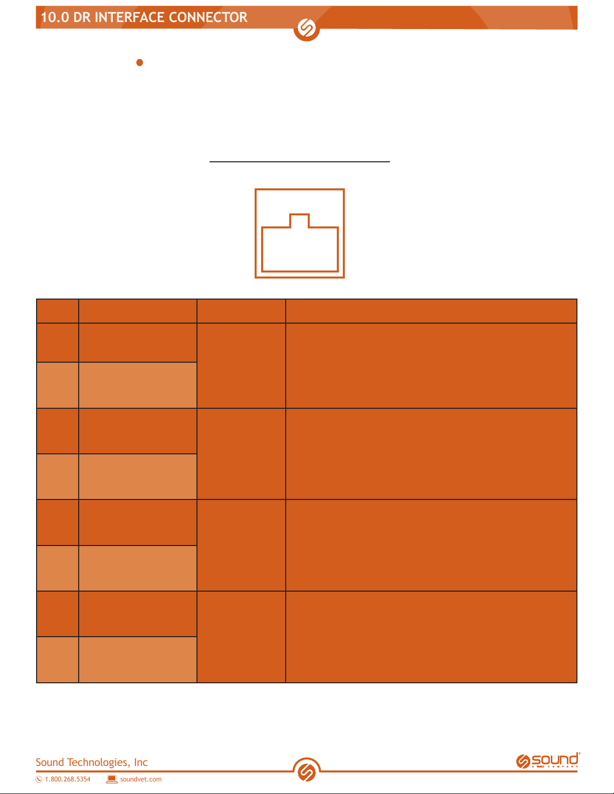
10.0 DR INTERFACE CONNECTOR
10.0 DR INTERFACE CONNECTOR
The SOUND TR9030GEN2 has an interface circuit for connection to a DR imaging system. When
using a DR system, we recommend that you connect the interface cable to the x-ray unit using
this connector.
Interface Connector Description
Model: RJ45
Signal name IN / OUT Functions
1READY_REQ_(+)
OUTPUT
Filament On signal
Indicates that a lament on signal is ordered from
the SOUND TR9030GEN2 side.
2READY_REQ_(-)
3REMORT_SW
INPUT Remote control enable signal
4REMORT_SW
5X-RAY_REQ_(+)
OUTPUT
X-ray On signal
Indicates that an X-ray exposure On signal is
ordered from the SOUND TR9030GEN2 side.
6X-RAY_REQ_(-)
7X-RAY_COM_(+)
INPUT
X-ray release signal
Checks whether or not imaging is ready at the DR
system side after receiving X-ray exposure signal
(RX_REQ) from the SOUND TR9030GEN2 side.
8X-RAY_COM_(-)

Sound Technologies, Inc
1.800.268.5354
soundvet.com
10.0 DR INTERFACE CONNECTOR
SOUND TR9030GEN2 DR system side
Interface Signal Description
READY_REQ
1.
2.
3.
4.
5.
7.
6.
8.
Detect Ready
(Filament signal ON)
SOUND TR9030GEN2
Table of contents


