SoundMax SM-CMD3012 User manual

2
De a r custom er!
Thank you for purchasing our product. For safet y, it is st rongly recom mended t o read t his m anual carefully
before connect ing, operating and/ or adjusting the product and keep the manual for reference in t he future.
Ta ble of cont e nt s
Table of contents............................................................................................... 2
Important safeguards......................................................................................... 3
Accessories....................................................................................................... 4
Installation/connection ....................................................................................... 5
Unit controls ....................................................................................................10
General operations............................................................................................14
Radio operations...............................................................................................18
TV tuner operations ..........................................................................................22
Disc/USB/SD/MMC operations.............................................................................23
DVD Setup menu..............................................................................................28
Handling and cleaning discs................................................................................31
Troubleshooting guide .......................................................................................32
Specification ....................................................................................................33

3
I m porta nt safegua rds
‚Read carefully t hr ough the m anual t o fam iliarize yourselves with t his unit .
‚Keep this manual handy as a reference for operating procedures and precaut ions. Do not allow persons
who have not read t hrough t his m anual t o use this unit .
‚“ CLASS 1 LASER PRODUCT”
This product contains a laser diode of higher class than 1. Laser beams from the optical pickup are
dangerous to t he eyes. To ensure cont inued safety, do not rem ove any covers or attempt to gain
access t o t he inside of t h e product . Refer all servicing t o qualified personnel.
‚Do not allow this unit to come into cont act wit h liquids. Electrical shock could result. Also, dam age to
this unit , sm oke, and overheating could result from contact with liquids or dust. Protect this unit from
m oist ure.
‚Make sure that foreign objects do not get inside the unit ; t hey may cause m alfunct ions, or creat e safet y
hazar ds such as elect rical shock or laser beam exposure.
‚The beginning of operation is the moment of the unit installation. Before use the device in winter it is
recommended to heat up the passenger compartment during 20 seconds or to the operation
t em perat ur e.
‚Using the unit wit h the t emperature t hat goes beyond t he operat ion tem perat ure great ly decreases the
operat ion resource of the screen and other com ponents of the unit and can result in an outage.
‚Disconnect t he vehicle’s negativ e bat tery t erm inal while m ount ing and connect ing t he unit .
‚The unit is designed for negative terminal of the battery, which is connected to the vehicle metal.
Please ensure it before inst allat ion.
‚When replacing the fuse, be sure to use one with an ident ical am perage rat ing. Using a fuse wit h a
higher am perage rating m ay cause serious dam age to t he unit.
‚Do not allow the speaker wires to be shorted together when the unit is switched on. Otherwise it may
overload or burn out t he power amplifier.
‚Make sure you disconnect the power supply and aerial if you will not be using the system for a long
period or during a t hunderstorm .

4
‚Make sure you disconnect the power supply if the system appears to be working incorrectly, is making
an unusual sound, has a strange smell, has smoke emitting from it or liquids have got inside it. Let a
qualified t echnician check the system .
‚Always keep t he volum e low enough so t hat you can hear sounds from outside t he vehicle.
‚Should t his product fail t o oper at e properly, contact your dealer or nearest ser vice center.
Accessories
1. Receiver 1 pc
2. Rem ot e controller 1 pc
3. Protect ive case for front panel 1 pc
4. I SO cab le set ( A+ B) 1 pc
5. Mounting parts:
Mounting sleeve 1 pc
Flat washer 1 pc
Spr ing washer 1 pc
Nut 1 pc
Out er tr im ring 1 pc
Release keys 2 pcs
Metal st r ap 1 pc
Screw 4 pcs
Rear m ounting bolt 1 pc
Rubber cushion 1 pc
6. Consum er inform at ion 1 pc
7. Warrant y card 1 pc
8. I nst ruct ion m anual 1 pc

5
I n st a llat ion / conne ct ion
‚Choose the mount ing locat ion w here the unit will not int erfere with t he norm al driving funct ion of t he
driver.
‚Before finally inst alling the unit, connect t he wiring and m ake sure that t he unit works properly.
‚Consult w it h your nearest dealer if installat ion requires the drilling of holes or ot her m odifications of the
vehicle.
‚Install the unit where it does not get in the driver's way and cannot injure the passenger if there is a
sudden stop, like an em ergency st op.
‚I f inst allat ion angle exceeds 30° from horizont al, the unit m ay not perfor m properly.
‚Avoid installing t he unit where it would be subject t o high tem perature, such as from direct sunlight, or
from hot air, fr om t h e heat er, or where it w ould be sub j ect t o d ust , d ir t or excessiv e v ibrat ion .
D in Fr ont / Re ar - Mount
This unit can be proper ly in stalled eit her from 'Front' ( convent ional DI N Fr on t - mou nt ) or ' Rear' ( DI N Rear-
m ount inst allat ion, ut ilizing t h readed screw holes at t he sides of t he unit chassis) . For det ails, refer t o t he
follow ing illustrated installation m et hods.
D I N FR ON T - M O UN T ( M e t h od A)
1. Car dashboard
2. Sleeve
3. Screw
4. Nut
5. Spring washer
6. Screw
7. Met al st rap
8. Flat washer

6
1. Install the sleeve into the dashboard; ensure it is installed with the correct side and there are no
ob st acles ( w ir es, dashboar d elem en t s, et c) for t he u nit inst allat ion .
2. After installing the sleeve into the dashboard, bend tabs fitting to the size of
the dashboard to fix t he sleeve in place.
3. Use the metal strap to fix the rear side of t he unit. Determ ine a place for fixing
and install the strap as shown in the picture. You can bend the strap to the
needed angle with your hands.
4. Make the necessary wire connect ions. Ensure the connections are correct.
5. I nstall t he unit int o t he sleeve until t he side locks ar e fixed.
D ism a nt ling t h e u nit
– Tr im fram e
– Fr am e uninst all d irect ion
– Release key insert ion
1. Sw it ch off t he unit and det ach t he front panel.
2. I nsert your fingers into t he groove in the front side of t he trim fram e ( apply
som e effort to det ach the fram e) . Pu ll t he fram e t o detach it.
3. Insert the supplied release keys into the both sides of the unit body to click,
as shown in the picture. To ext ract t he unit from t he dashboard, pull the
release keys or t he unit body t o pull it out . Before detaching t he unit, ensure
it is not fixed with t he m et al st rap.
Trim f ra m e inst a lla t ion
To install the trim frame, press it to the unit body and push it to fix it in place. This should be done before
installing t he front panel; ot herwise you are not able t o install the t rim fram e. When the trim frame being
inst alled, t he side wit h t he groove shou ld face dow n and fixed first .

7
2 . D I N R EAR - M OU N T ( M e t h od B)
For t his m ethod, use t he screw holes in t he lat eral sides of t he unit. Fix t he unit w ith the help of the fact ory
radio m ount ing bracket s.
1. Select a posit ion in which t he screw holes of t he bracket s ( 3) are aligned
with t he screw holes in t he unit body, and screw in two screws ( 2) in each side.
2. Screw.
3. Fact ory radio m ount ing brackets.
4. Vehicle dashboard.
5. Lock ( rem ove t his par t) .
N ot e : The outer t rim fram e and mounting sleeve are not used for m et hod of installation.
I nst a lling t he f ront p a ne l
Insert the left locker on the receiver into the left groove of the panel, and then insert the right locker into
the right groove. Lift the panel and press on the upper part of the panel until a click. Ensure the panel is
fix ed pr operly , ot herw ise error sy m bols m ay be disp lay ed or som e but t ons w ill n ot funct ion .
To detach t he front panel, press OPEN but t on. When the panel is in horizont al position, det ach t he left part
of the panel from t he locker, and then det ach the right part.
Ant i- t h ef t syst e m
The front panel of this unit can be stored in the included protective case when not in used and carried away
when you leave t he vehicle t o det er t heft .
Switch off the power of the unit. Detach the front panel, then put it to the protective case and take it with
you.
Cautions: The cont rol panel can easily be dam aged by shocks. Aft er r em oving it , place it in a protect ive
case and be careful not to drop it or subject it to st rong shocks.
The r ear connect or t hat connect s t he m ain unit and t he contr ol panel is an extrem ely im portant part . Be
careful not t o dam age it b y pressing on it wit h fingernails, pens, screwdrivers, et c.
N ot e : If the control panel is dirty, wipe off the dirt with soft, dry cloth only. And use a cotton swab soaked
in isopropyl alcohol t o clean the socket on t he back of th e control panel.
8
Ele ct r ica l Con n ect ion
Conn ect or A Conn ect or B
1. - 1. Rear right speaker ( + )
2. - 2. Rear right speaker ( - )
3. - 3. Fr ont r ig ht speak er ( + )
4. Mem ory + 12V 4. Fr ont r ig ht speak er ( - )
5. Aut o antenna out put 5 . Fron t left speak er ( + )
6. - 6. Fr on t left speak er ( - )
7. + 12V ( t o ignit ion key) 7. Rear lef t speak er ( + )
8. Ground 8. Rear lef t speak er ( - )

9
I SO Conn ect ion t a ble
Fu nct ion
Lo ca t ion
Conn ect or A Conn ect or B
1 - Rear r ight ( + ) - Pur ple
2 - Rear right ( - ) - Pur ple/ Black
3 - Fr ont r ight ( + ) - Gr ey
4Battery + 12V/ Yellow Fron t right ( - ) - Gr ey / Black
5Aut o Antenna - Blue Front left (+ ) - White
6 - Fr on t left ( - ) - White/ Black
7I gnition/ Red Rear left (+ ) - Green
8Ground/ Black Rear left ( - ) - Green/ Black
N ot e : Power antenna wire is intended for power supply of the antenna and for remote control of an
addit ional amplifier.
Park in g w ir e con ne ct ion
I f Parking cable is connected to hand brake switch, the video display of the TFT m onitor will be controlled by
driving status, system setup and input video sources. When the car is moving ahead, if the video disc is
played, the screen shows “ Att ention! You cannot use this funct ion while driving” , and blank screen. The
above warning screen will pr event t he driver fr om wat ching im ages.

10
Un it cont rols
Fr on t p ane l
1. I R sensor
2. 1/ PLAY/ PAUSE but t on
3. POWER/ MUTE button
4. MODE button
5. VOLUME+ but t on
6. MENU button
7. BND button
8. 6/ DI R+ button
9. NEXT button
10. TFT display
11. OPEN but ton
12. USB por t
13. PREVIOUS button
14. 2/ I NT butt on
15. 3/ RPT but ton
16. OK button
17. VOLUME- butt on
18. AS/ PS butt on
19. 4/ RDM button
20. 5/ DI R- but ton
21. A/ V in j ack

11
I nner p a ne l
1. Mem ory card slot
2. Ej ect but t on
3. Panel stat us indicat or
4. RESET butt on (hole)
5. Disc loading slot
Pr essing RESET hole w ill erase t he clock set t ing and st ored st at ions.
Panel stat us indicat or light s up when you flip down t he panel an d flashes when you rem ove the panel.

12
Re m o t e co nt ro lle r ( RC)
1. MODE butt on
2. PWR but t on
3. BND/ RDM butt on
4. ENTER but ton/ Cursor but tons
5. STEREO/ MONO butt on
6. PTY/ PROG button
7. P.SCN/ RPT butt on
8. SEEK- / PREVIOUS butt on
9. AF/ TA button
10. STOP/ PBC button
11. OSD button
12 . Num ber but t ons
13. PLAY/ PAUSE butt on
14. MUTE but t on
15. MENU button
16. SUB- T but t on
17. SETUP but t on
18. ANGLE button
19. I NT but ton
20. A- B/ ZOOM but t on
21. VOL+ button
22. SEEK+ / NEXT but t on
23. SEL but ton
24. AUDI O/ GOTO but ton
25. VOL- button

13
Ch a nging t h e ba t t e ry
1. Pr ess the cat ch and at t he sam e t ime pull out the battery t ray ( pic. 1) .
2. I nsert the 1 lit hium bat t ery, t ype CR2025 (3V) battery w it h t he stam ped
( + ) m ark facing upward. I nsert the bat tery tr ay int o t he r em ote cont roller
( p ic. 2 ) .
W ar ning:
‚Store the battery where children cannot reach. If a child accidentally swallows the battery, consult a
doct or im m ediat ely.
‚Do n ot recharge, short, disassem ble or heat the batt ery or dispose it in a fire.
‚Do not expose or bring int o contact t he bat tery with other m et allic m aterials. Doing t his may cause the
bat t ery t o give off heat, crack or star t a fire.
‚When throwing away or saving the battery, wrap it in tape and insulate; otherwise, the battery may
giv e off h eat , crack or st art a fire.
‚Please direct t he Rem ote cont roller to the I R sensor of t he front panel.
Pic. 1 Pic. 2

14
Genera l operations
Re se t t h e u n it
Operating the unit for the first time or after replacing the car battery, you must reset the unit. Press RESET
but t on (hole) with a pointed object ( such as a ballpoint pen) t o set t he unit to init ial state.
N ot e : When some errors occur, you can also press RESET button to resume to normal, and it will erase the
clock set t ing and som e m em orized funct ions.
Tur ning t he u n it on / off
Press any button on the panel or t he RC (except OPEN butt on) t o t urn on the unit. Press and hold
POWER/ MUT but t on on t he panel or p ress POWER b ut t on on t he RC t o t ur n off t he unit .
M ode se le ct ion
Repeatedly press MODE button on the RC or on the panel to select a mode: Tuner = > DVD => USB =>
Card = > TV = > AV I N.
N ot e : The DVD, Card and USB m odes are only available when corresponding st orages are insert ed int o the
unit.
M ut e funct ion
Press MUTE butt on on t he RC or POWER/ MUT butt on on t he panel to t urn off the sound. “ MUTE” appears on
the TFT. Pr ess t he button again or adjust volume t o resume t he sound output .
Volum e control
Press VOL+ / VOL- butt ons on the RC or VOLUME+ / VOLUME- buttons on t he panel t o decrease or increase
sound volume level.
Se t ting t h e sound ch ar a ct er ist ics
Press and hold OK but t on on front panel or press SEL but ton on the RC to select t he audio set t ing m enu:
BASS = > TREBLE = > BALANCE = > FADER = > EQ. Press UP/ DOWN cursor buttons on the RC or VOLUME+ / -

15
but t on on the panel to select the audio set ting item . Press ENTER butt on or RI GHT cursor but ton on t he RC
or OK butt on on t he panel t o en ter t he select ed it em .
Press LEFT/ RI GHT buttons on t he RC or VOLUME+ / VOLUME- but t ons on t he panel to adjust t he audio
setting. Press and hold OK button on the panel or press SEL butt on on the RC again to save the setting and
ret urn to current m ode.
N ot e : If turn off the power, all the settings of each mode will be saved. If turn off the ACC power, all the
settings w ill be clear and becom e fact ory default set t ing. I f you don’t adjust set t ing within 3 seconds after
select ing t he desired set t ing item , t he unit will autom at ically ret urn t o the current m ode.
Sy st e m se t up
Press MENU butt on on the panel or RC to enter Setting Menu. Press UP/ DOWN cursor buttons on the RC or
VOLUME+ / - but t ons on the panel to select a menu page. Press ENTER but t on or RI GHT cursor butt on on t he
RC or press OK but t on on the panel t o enter t he page. Press LEFT/ RI GHT cursor but tons on t he RC or
VOLUME+ / VOLUME- buttons on the panel to select an it em , then press OK but t on on the RC or SEL but t on
on t he panel t o adj ust the set t ing.
Press MENU but ton t o ret urn to last sett ings list .
AUDIO MENU
‚Bass: Support 10 levels. Default level is 0.
‚Treble: Support 10 levels. Default level is 0.
‚Balance: Support 10 levels for each left and right channel. Default is left equal t o right .
‚Fader: Support 10 levels for each front and rear channel. Default is front equal t o rear.
‚EQ DSP: FLAT = > CLASSI CS = > POP = > ROCK = > DSP OFF.
PI CTURE MENU ( available in DVD/ USB/ Card m od es only )
‚Red: Adj ust level of red color. Support 50 levels. Default level is 25.
‚Green: Adjust level of green color. Support 50 levels. Default level is 25.
‚Blue: Adj ust lev el of blue color. Support 5 0 levels. Default level is 25.
‚Bright ness: Adj ust level of screen bright ness. Support 50 levels. Default level is 25.
‚Cont rast : Adj ust lev el of scr een con trast . Support 50 levels. Default level is 25.
‚Sharpness: Adj ust level of screen sharpness. Support 15 levels. Default level is 10.

16
‚Screen: Adjust screen aspect : 16: 9 = > 4: 3 = > FULL.
‚Color reset : Resume color default st atus. (Select YES or NO with cursor b utt ons, press ENTER but t on on
the RC or OK but t on on the panel to confirm ) .
RDS SETUP:
‚TA: Seek/Alarm. In TA SEEK mode, When newly tuned station does not receive TP information for 5
sec, t he radio ret unes to next station which has not t he sam e stat ion (PI ) as the last stat ion, but has
t he TP inform ation. I n TA ALARM m ode, When this m ode is select ed, any aut om at ic ret une mode is not
activated. Only double beep sound (ALARM) is shown. So, in this mode, the unit keeps the current
st ation.
‚PI : Mute/ Sound. When different PI sound (DIP) is heard once in a while, the DIP’s sound will be heard
for less than 1 second. Under t he sam e situation, a m ut e sound will be heard for less t han 1 sec.
‚RETUNE: Long/ Short. RETUNE refers to the tim e period the unit allows for radio scan when reception is
int errupt ed. “ S” r ep resent s a t im e per iod of 3 0 seconds and “ L” rep resen ts a t im e per iod of 9 0 seconds.
‚MASK: DPI/ALL. During MASK DPI mode, the unit will mask only the AF which has different PI, this is
the default m ode; during MASK ALL mode, the unit will mask the AF which has different PI and no RDS
signal w it h hig h field st rengt h.
‚EON TA: DX/ Local. When the field strength level of EON linked station is less than the threshold level,
t he radio does not swit ch t he stat ion. EON TA switching informat ion is implem ented by t he inform at ion
of the current station. When EONTA DX mode is select ed, t he unit will sw it ch t o the radio station
t ransm it t ing the TA signal.
‚REG: REG ON ( t he receiver accept s regional v ar ian t s of t h e t u ned st at ion wit h REG icon t u rned on) , and
REG OFF ( t he receiv er ignor es r egional v ar iant s) .
‚TA VOL: Adj ust level of TA volum e, support 50 levels. Default level is 15.
EXPERT MENU
‚DX: Set sear ch r adio st at ion by DX or LOCAL m ode. DX = > LOCAL.
‚St ereo: Set radio audio at STEREO or MONO m ode, STEREO = > MONO.
‚Beep: Set press keys’ sound. 2ND = > ALL = > OFF.
‚Loud: Set loudness on or off. OFF = > ON.
‚Backlight : Set OSD backlight : HI GH = > LOW = > MI D.

18
Ra dio ope rat ions
Ba n d se le ct ion
Press BND/ RDM but t on on t he RC or BND but t on on the panel to swit ch t o the bands in t he following order:
FM1 - FM2 - FM3 ( OI RT) – MW1 ( AM1) – MW2 ( AM2 ) .
M a nu al/ au t om a t ic t un ing
‚Manual tuning: Press and hold PREVIOUS/ NEXT buttons on the RC or panel to enter m anual tuning
mode. MANUAL will be displayed. Press these buttons repeatedly to change the frequency upward or
downward step by step.
‚Aut om at ic t uning: Press repeatedly PREVIOUS/ NEXT but tons on the RC or panel to st art autom at ic
seeking for an available radio station downward or upward. After being found the station will be played.
To st op seeking, press one of t hese butt ons again .
Prog ram m ing st at ion s
There are 6 numbered preset buttons, under which you can store and recall stations for each band (18 FM,
12 AM). Select the needed station, then press and hold a preset button. The station will be saved in the
m em ory under the corresponding num ber. To recall a st or ed st at ion, press t he corresponding preset but ton.
Au to m e m ory st or e/ Prese t sca n
Aut o st ore: Select a band, press and hold AS/ PS but t on on the panel or P.SCN/ RPT butt on on t he RC t o
enter auto store m ode. The radio will autom atically store 6 stations to the 6 preset memories of the current
band. To st op auto store, press the butt on again.
N ot e : During aut o stat ion preset , t he unit will search and store stat ions with t he st rong signal first , and
t hen weak er signal st at ions unt il the m em ories are full.
Preset scan: Select a band, press AS/ PS but ton on the panel or P.SCN/ RPT button on t he RC to scan all
preset stat ions in th e m em ories of t he current band. To st op preset scan, press t he butt on again.

19
St e r eo/ M ono r e cep t ion
I n FM m ode, press STEREO/ MONO butt on on t he RC t o select st ereo or m ono signal recept ion m ode.
On- scree n display
Press OSD butt on on the RC to show enabled PTY funct ion icon.
RDS background
RDS service availabilit y varies wit h areas. Please under stand if RDS service is not available in you area, t he
follow ing service is not available.
AF ( Alt er na tiv e fr e qu e ncies) f un ct ion
Press and hold AF/ TA but t on on the RC or BND button on t he panel t o enable AF funct ion. When the radio
signal strengt h is poor, enabling the AF funct ion will allow the unit t o aut om at ically search another stat ion
w it h t he sam e PI ( Pr ogram I dent ificat ion) as the curren t st at ion but wit h st ronger signal st ren gt h.
N ot e : AF indicat or on the display will flash until RDS inform ation is received. I f RDS service is not available
in your area, t urn off the AF m ode.
TA ( Tra ffic alar m ) fun ction
Press AF/TA button on the RC or press and hold MODE button on the panel to activate the traffic alarm
function.
When TA funct ion is act ivat ed, it will search t he st ation wit h TA inform at ion aut om at ically. I f th ere is no TA
inform at ion, it will search t he station wit h TP inform at ion autom at ically, if ther e is no TP inform at ion either,
it will ret urn t o t he previous stat ion after searching.
When receiving the stat ion with TP informat ion but wit hout TA inform at ion, TP icon is on and TA icon keeps
blinking; when receiving the stat ion wit h TP and TA inform at ion, bot h TP and TA icons ar e on.
When playing in other m ode and TA inform ation is received, it will change t o t he radio m ode aut om at ically.
Aft er playing over, it w ill ret urn to the previous m ode. Press AF/ TA button on t he RC or press and hold
MODE but t on on the panel once to ignore t he received TA inform at ion, do it t wice t o turn off t he funct ion.

20
PTY ( Prog ram t yp e) fu nct ion
Press PTY/PROG button on the RC to open PTY program type list, and repeat pressing PTY/PROG button to
select a PTY type. After selecting the program type you want, press number buttons 1 - 6 on the RC or on
the panel t o start search. Press it again t o stop the PTY search. I f PTY code is different or not available, "PTY
NONE" blinks on the display.
Othe r functions
Press MENU butt on on the panel or RC to enter Setting Menu. Press UP/ DOWN cursor buttons on the RC or
VOLUME+ / - but t ons on the panel to select RDS SETUP page. Press ENTER button or RIGHT cursor but t on on
t he RC or press OK but ton on t he panel t o ent er the page. Press LEFT/ RI GHT cursor but tons on t he RC or
VOLUME+ / VOLUME- but t ons on the panel t o select an item , and then press OK butt on on t he RC or SEL
but t on on the panel to adj ust t he set ting.
Press ENTER but t on or RI GHT cursor but ton on the RC or OK button on the panel to confirm , press MENU
but t on to ret urn to last settings list .
RDS SETUP
‚TA ALARM/ SEEK: I n TA SEEK mode, the unit w ill seek for t r affic announcem ent pr ogr am ; in TA ALARM
m ode, t he alar m is set off.
‚PI SOUND/ MUTE: Choose eit her PI sound or PI m ute. PI sound refers t o the reception noise when the
AF function tries t o scan alternat ive frequency.
‚RETUNE S/L: RETUNE refers to the time period the unit allows for radio scan when reception is
interrupted. SHORT represents a time period of 30 seconds and LONG represents a time period of 90
seconds.
‚MASK DPI/ALL: During MASK DPI mode, the unit will mask only the AF which has different PI, this is
the default m ode; during MASK ALL mode, the unit will mask the AF which has different PI and no RDS
signal w it h hig h field st rengt h.
‚EON TA DX/LOCAL: EON (Enhanced Other Networks) - This unit is equipped with the latest technology
of EON cont rol, so that when you are list ening t o Radio or CD, if t here is any travel announcement from
a nearby local station, the radio will already know the frequency of that radio station. Then it will
receive the station, turn up the volume, or interrupt the playback for the duration of the
Other manuals for SM-CMD3012
1
Table of contents
Other SoundMax Car Stereo System manuals

SoundMax
SoundMax SM-CCR3033 User manual

SoundMax
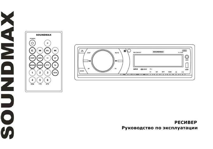
SoundMax SM-CDM1047 User manual

SoundMax
SoundMax SM-CCR3054F User manual

SoundMax
SoundMax SM-CSL602 User manual

SoundMax
SoundMax SM-CSL502 User manual

SoundMax
SoundMax SM- CCR3038 User manual

SoundMax
SoundMax SM-CCR3060FB User manual

SoundMax
SoundMax SM-CCR3035 User manual