Soundoff Signal INTERSECTOR ENT2B Series User manual
To review our Limited Warranty Statement & Return Policy for this or any SoundOff Signal product please visit our website at www.soundoffsignal.com and select the “Warranty & Returns”
link along the left column of our home page. If you have questions regarding this product please contact Technical Services, Monday - Friday, 8 am to 5 pm at 1.800.338.7337, press #4 to
skip the automated message. Questions or comments that do not require immediate attention may be emailed to [email protected].
1.800.338.7337. / www.soundoffsignal.com / Thank you for trusting us with your safety!
OPERATION:
For details on operation see page with ‘Flash
Patterns’ table on last page.
Please see separate sheet
for Technical Specifications
• Warning devices are strictly regulated and governed by Federal, State and Municipal ordinances.
These devices shall be used ONLY on approved vehicles. It is the sole responsibility of the user of these
devices to ensure compliance.
• DO NOT install this product or route any wires in the Air Bag Deployment Zone. Refer to your vehicle
Owner’s Manual for the location of any air bag deployment zones.
• DO NOT connect this device to a strobe power supply. This product is self-contained and does not
require an external power supply.
ENT2B3(x) 7.10
Important Information:
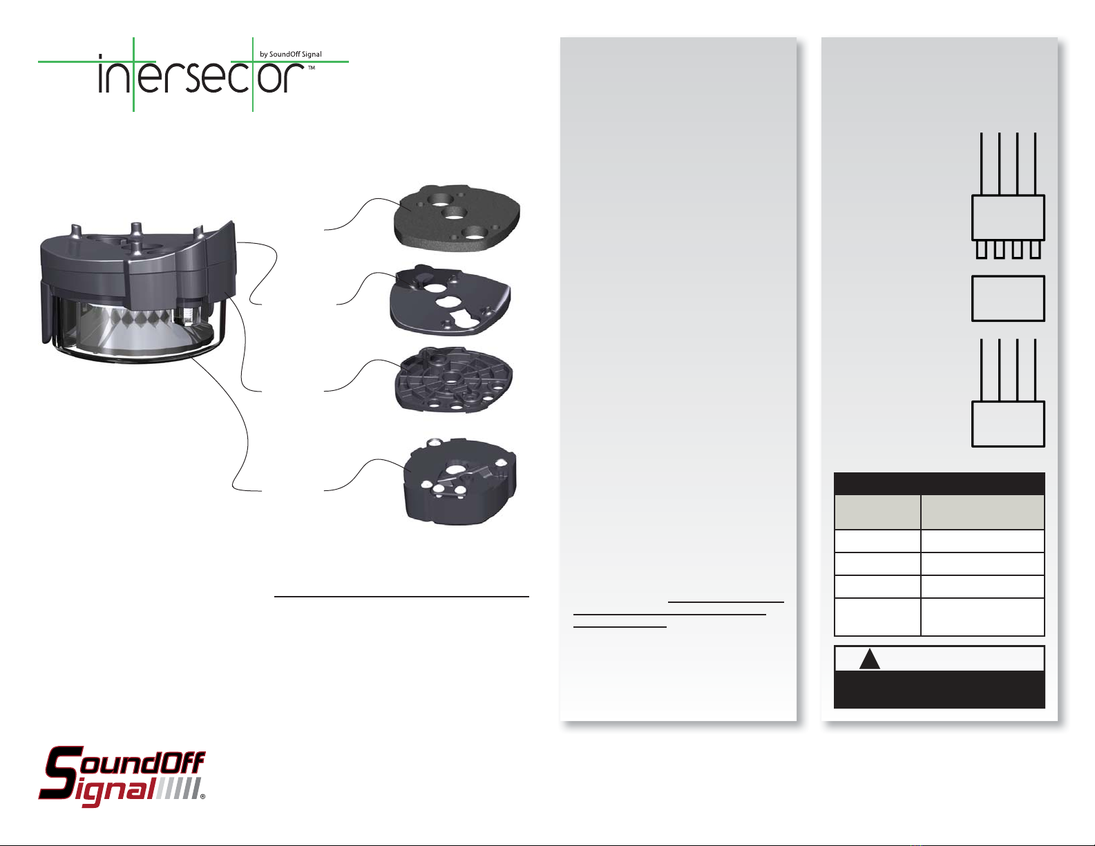
The INTERSECTOR LED Light is designed to
be mounted under the vehicle’s side mirrors
and provide a warning signal to the front
and sides. It can also be surface mounted.
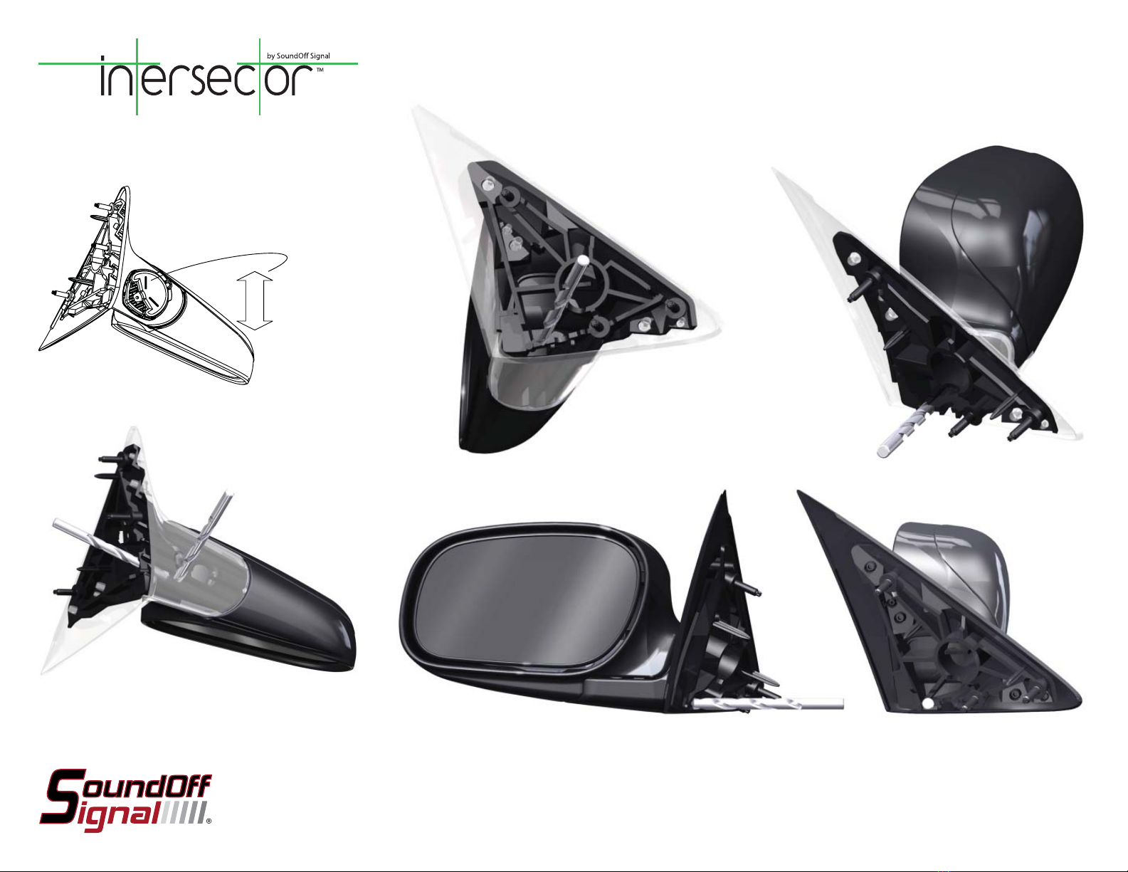
INSTALLATION:
Loosely assemble Intersector Light, correct
wedge block and curve block (P=Passenger,
D=Driver’s side, Crown Vic and Dodge
Charger only) and position assembly below
side rear view mirror as shown at left.
Carefully remove light from stack without
changing position of wedge block. Mark and
drill pilot holes for #6 sheet metal screw.
Drill 3/8” hole in mirror shell if wire is to
be routed internally. If wire will be routed
external of the mirror shell this step can be
ignored.
Dismount mirror from door.
The following is particular to the Ford Crown
Vic but can be applied to other vehicles as
well:
After pilot holes for #6 sheet metal screws
are drilled, a 3/8” bit should be used to
drill hole in race way next to mirror power
race. A 3/8” hole should then be made
between the pilot holes and then angled
toward the race way as shown in Figures
2-6 (second page). It is important to avoid
drilling through the power cable as this will
damage the mirror.
Using #6 machine screw, washer and
square nut assemble light and appropriate
wedge block, curve block (if required)
and gasket. Route wire carefully through
3/8” hole and into door. Use appropriate
#6 sheet metal screws to attach light to
underside of mirror. DO NOT OVERTIGHTEN
SCREWS AS THIS MAY DAMAGE THE
MIRROR OR LIGHT. Mirror may now be
replaced on vehicle.
Attach supplied female connector and make
other appropriate wiring connections inside
of door.
WIRE HOOK-UP TABLE
WIRE COLOR:
(ALL WIRES 20ga)
CONNECT TO:
(FROM FLASHER ONLY)
RED +10-16Vdc
WHITE Pattern Select / Sync
BLACK Ground (-)
GREEN Cruise Mode (+10-
16Vdc)
!
WARNING
This product contains high intensity LED devices. To
prevent eye damage, DO NOT stare into the light
beam at close range.
Mirror Light
Shown with
optional cord
strain relief
Wedge Block
0°, 5° and 10°
Curved Surface
Adaptor (used on
Crown Vic and
Charger only)
Foam Gasket
RED
WHITE
BLACK
GREEN
DBCA
DBCA
RED
WHITE
BLACK
GREEN
FEMALE
CONNECTOR
MALE
CONNECTOR
FROM FLASHER
INTERSECTOR
LIGHT
ALL WIRES 22ga
IMPORTANT:
Power should only be
supplied through RED
WIRE of flasher harness
and must be fused with
a 3A, user supplied,
in-line fuse. Failure to
install this fuse will create
a fire hazard and will
damage the Intersector
Light. Connecting the
Intersector light to any
power source directly
WILL permanently
damage the light and will
void warranty.
INTERSECTOR LED LIGHT
ENT2B3(x)

ENT2B3(x) 7.10
POWER HARNESS WITH IN-LINE FLASHER
INTERSECTOR LIGHT WITH CABLECONNECTOR
SQUARE NUT WASHER 3/8” MACHINE
SCREW
USE TO JOIN LIGHT TO WEDGE BLOCK AFTER
CORD EXIT IS DETERMINED
3/4” SHEET
METAL SCREW
1/2” SHEET
METAL SCREW
USE WHEN
CURVE BLOCK IS
USED
USE WHEN
CURVE BLOCK IS
NOT USED
GASKET CURVED SURFACE ADAPTOR
(CROWN VIC OR CHARGER)
P=PASSENGER SIDE
D=DRIVER SIDE
WEDGE BLOCKS
UTILITY BLOCK
0° (HORIZONTAL)* 10° FOR TAHOE*
5° FOR CROWN
VIC, IMPALA AND
CHARGER*
DEGREE DESIGNATION IS EMBOSSED IN PART
PASSENGER OR
DRIVER SIDE
DESIGNATION IS
EMBOSSED IN PART
6-32 MACHINE SCREW
WASHER
IF DESIRED CORD MAY BE
EXTERNAL OF THE MIRROR
BY USING THE STRAIN RELIEF
AND THREAD CUTTING
SCREWS SUPPLIED
SQUARE NUT (USE MASKING
TAPE TO HOLD IN PLACE)
GASKET IS ALWAYS
POSITIONED NEXT TO MIRROR
SHELL RED
BLACK
GREEN
WHITE
FROM FLASHER
FROM LIGHT
COLORS AND LETTERS ON
CONNECTORS MUST MATCH
DO NOT INSTALL CONNECTOR
UNTIL LIGHT IS INSTALLED ON
MIRROR AND WIRE IS RUN TO
FINAL TERMINATION POINT
USER SUPPLIED 3A FUSE ON RED WIRE
DO NOT CONNECT DIRECTLY TO POWER
INTERSECTOR LED LIGHT
ENT2B3(x)
* INDICATES FOR WHAT PART WAS DESIGNED. INSTALLATION
ON OTHER VEHICLES IS INSTALLER’S RESPONSIBILITY.
ENT2B3(x) 7.10
Light should be positioned so that raised lines on lens is aligned
with long axis of vehicle.
VEHICLE LONG
AXIS
Drilling of inner part is only required on Crown Vic. Tahoe and
Impala mirrors have sufficient clearances for cable. Cable for
Charger must be bundled with power cable of vehicle.
12 3
45 6
INTERSECTOR LED LIGHT
ENT2B3(x)

ENT2B3(x) 7.10
PATTERN RESET
1. Remove power.
2. Place WHITE (sync) wire to ground.
3. With sync wire grounded, re-power RED wire.
4. Maintain for one second (light will dim).
5. Remove power and ground (pattern 1 set).
SINGLE LIGHT HEAD SET UP AND PATTERN SELECTION
1. Disconnect WHITE wire from any connections if applicable.
2. Turn INTERSECTOR LED LIGHT ON by applying power to RED WIRE
from flasher. IMPORTANT NOTE: Power harness with in-line flasher
(PNT(x)FLA) MUST be used between power and light. Any other
flasher WILL cause permanent damage and void warranty.
3. Momentarily touching and removing the WHITE wire to ground
will advance the INTERSECTOR LED LIGHT to the next flash pattern.
Touching and removing the WHITE wire for more than a few seconds
will allow you to change the INTERSECTOR LED LIGHT to the previous
pattern. See flash pattern table. Continuing to touch and remove the
WHITE wire to ground will allow you to scroll through the pattern list.
After pattern #30 is reached the list will start over again at pattern
#1.
SINGLE COLOR CONFIGURATIONS
Follow the ID selection steps and set the INTERSECTOR LED LIGHT to
the following ID:
ID #2 - Single Color ID #4 - Single Color
Single Color - Simultaneous Flash Patterns:
- Set light heads to same ID (#2 or #4).
Single Color - Alternating Flash Patterns:
- Set one light head to ID #2 and another to ID #4.
MULTIPLE LIGHT HEAD SET UP AND PATTERN SELECTION
1. Set ID#
a. Connections
i. RED: +10-16Vdc
ii. WHITE: +10-16Vdc (Note: you will need to disconnect after
power is applied)
iii. BLK: Ground
iv. GREEN: NO CONNECTION REQUIRED FOR ID SELECTION
b. Apply power to unit
c. Without disconnecting power from unit, disconnect WHITE wire
d. Momentarily connect WHITE to Ground to change ID #
i. Identify ID# by number of sequential flashes
ii. Possible ID#s: 2 or 4
e. Disconnect Power to exit ID mode
2. Set Pattern - Must be done individually to each light prior to
syncing
a. RED: +10-16Vdc
b. BLACK: Ground
c. While light is powered, tap WHITE wire to ground to advance to
the next pattern (SEE pattern table at right)
d. Disconnect Power
3. Sync Lights
a. Once desired pattern has been selected for all light heads
connect all white wires and insulate with electrical tape.
4. Connect Master Switch for Application.
TECHNICAL SPECIFICATIONS
Overall Dimensions: 1.88”H x 2.88”W x 2.93”D
Flash Patterns: 30 flash patterns
Input Voltage Range: 10 - 16 Vdc (fused)
Current Consumption: 1.5A (maximum)*
# of LEDs: 9 Generation 3 LEDs
Light Sync Technology: Yes (4 Maximum)
Operating Temperature: -40º to +65º C
* PATTERN DEPENDENT
Flash Patterns
Pattern Name 1 Light Alternating
2 Lights
Simultaneous
2 Lights
F.P.M.
(Flashes /
Minute)
1. Quint
xx x70
2. Warp
x x x 350
3. Inter-Cycle Flash
xx
4. Double Flash
xx x70
5. Quad Flash
xx x80
6. PowerPulse™
x x x 180
7. RoadRunner™
x x x 113
8. Q-Switch™
xx
9. RoadRunner™ Steady Burn
x x 113
10. Quad Steady Burn
xx 80
11. E-Ideal Single Flash
x x x 200
12. E-Ideal Double Flash
x x x 146
13. Quad2 Flash
xx x67
14. Double2 Flash
xx x95
15. PowerRunner
xx x
16. LCR Quint
xx x
17. Warp3
xx x
18. Ultra Warp
x x x 545
19. Thunder & Lightning
xx
20. Lite Speed
xx x85
21. SuperSonic
x x 170
22. LCR Lite Speed
xx x
23. SuperSonic Ultra
xx x
24. Tempo Shift
xx x
25. Tempo Shift Warp
xx x
26. SBE2
xx x67
27. C2
x x x 200
28. U2
x x x 176
29. Cyclone2
xx x
30. Chameleon2
xx x
PENT2BØ(x) Intersector High Diode Light (only, no flasher)
PNT2FLA: Intersector High Diode Inline flasher
PNT1WDG: Intersector Custom Wedge Set (0, 5 & 10 degree)
PNT1CRVØ1: Intersector Curved Surface Adaptor Set (1-Driver,
1-Passenger)
Replacement Parts & Accessories:
INTERSECTOR LED LIGHT
ENT2B3(x)
Popular Car Alarm manuals by other brands

UVI Group
UVI Group GPS-118V Installation and guide book

Toyota
Toyota RS3200PLUS troubleshooting guide

Fortin
Fortin EVO ONE Wiring and Setup Guide

Directed Electronics
Directed Electronics Security System and Convenience 125xv user guide

Bladox
Bladox Auto Alarm user guide

Audiovox
Audiovox PS-130I owner's manual


