SoundOFF bluePRINT ENGND20001 User manual

EVCS_Input Node 0419
1.800.338.7337 / www.soundoffsignal.com
1
INPUT NODE
PART NUMBER: ENGND20001
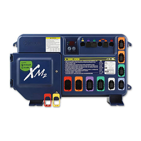
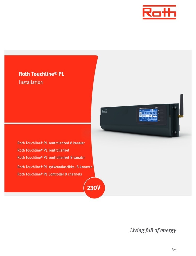
The Input Node provides 20 inputs for connection to vehicle devices.
•(13)ActiveHigh/LowInputs
•(7)ActiveHighInputs
CONNECTING INPUT NODE TO CENTRAL CONTROLLER
•ConnecttheInputNodetotheCentralControllerbyconnectingthesinglewireLINwiretotheCentralController
LINconnector.
IGNITION INPUT
•ConnecttheignitionswitchtoputtheInputNodeintolowpower(sleepmode)whenignitionisoff.Theignition
inputsignalisneededfornormaloperation.
.
Tech Specs
bluePRINT®Control System
Input Node
Input Voltage: 10-16Vdc (Negative Ground)
Maximum Input Current: NA
Outputs (Sum of ALL used Outputs
Shall Not Exceed 100Amps) None
IGN ON: Standby Current: 30 mA
IGN OFF: Sleep Current: 0.20 mA
Inputs:
20 Total
13x Active High/Low Inputs
7x Active High Inputs
1x Local IGN Input (Local Sleep Mode)
Reverse Polarity Protection: Protected
Transient Protection: Protected
High Voltage Protection: >16V; High Voltage Error Code Set
Low Voltage Protection: <9V; Low Voltage Error Code Set
Operating Temp: -40˚C to + 65˚C
Dimensions: 3.5” x 3.5” x .75”
Weight, Boxed: 5 oz.
Weight, Device Only: 4 oz.
Valid Input Threshold - High >7.5V
Valid Input Threshold - Low <1.5V
The Input Node is not waterproof. Install in a protected location away from excessive heat
and moisture.
SWITCHESNOTUSED
REDLED
GREENLED
GREENLED:IndicatesPower/Ignition(ash-
ing)andtransitionstosolidwhenthereis
LINactivity.REDLED:Indicatesaninputis
active.
•HIGHCURRENTinterconnectsmustbeproperlyterminated.Poorcrimpqualitycancauseheat
build-upandre.Followcrimpconnectormanufacturerinstructions.
•DONOTinstallthisproductorrouteanywiresintheAirBagDeploymentZone.Refertovehicle
Owner’sManualfordeploymentzones.
•DoNOTusesystemtodisconnectheadlights,brakelightsorothersafetyequipment.
•Unitmaybecomehottotouchduringnormaloperation.
•Failuretoproperlyinstallconnectors,fusesorwiringmaycausevehiclefailureorre.
•Installationmustonlybeperformedbytrainedtechnician.Installermustdeterminevehiclewiring
congurationandproperintegrationofsystem.
•Useproperwiregauge.Allpowerwiresconnectingtopositive(+)ornegative(-)batteryterminal
orlocalchassisground(-)mustbesizedtosupplyatleast125%ofmax.currentandproperlyfusedat
powersource.
•Installprotectivegrommetswhenroutingwirethroughrewallormetal.
WARNING
NOTICE:
Installers and users must comply with all applicable federal, state and local laws regarding use and installation of warning devices.
Improper use or installation may void warranty coverage.
To review our Limited Warranty Statement & Return Policy for this or any SoundOff Signal product, visit our website at www.soundoffsignal.com/tech-services/returns/.
If you have questions regarding this product, contact Technical Services, Monday - Friday, 8 a.m. to 5 p.m. or after hours 5 p.m. to 8 p.m. ET at 1.800.338.7337 (press #4).
SUPERIOR CUSTOMER RELATIONSHIPS. SMARTLY DESIGNED LIGHTING & ELECTRONIC SOLUTIONS.

EVCS_Input Node 0419
1.800.338.7337 / www.soundoffsignal.com
2
Function Wire Pin # Wire Color Activation
Input 1 1 Blue/White H/L
Input 2 2 Green/White H/L
Input3 3 Gray H/L
Ground 4 Black
LINData 5 LightGreen
Input 6 6 Brown/White H/L
Input7 7 Purple H/L
Input 8 8 White H/L
Input 9 9 Black/White H
Input 10 10 Gray/White H
Input 11 11 Purple/White H
Ignition 12 Pink/White
Input13 13 Blue H/L
Input 14 14 Green H/L
Input15 15 Yellow H/L
Input 16 16 Orange H/L
Power 17 Red
Input 18 18 Pink H/L
Input 19 19 Red/White H/L
Input 20 20 Brown H/L
Input 21 21 Yellow/White H
Input 22 22 Orange/White H
Input23 23 Red/Black H
Input 24 24 LightGreen/White H
PIN#24-LightGreen/White
PIN#23-Red/Black
PIN#22-Orange/White
PIN#21-Yellow/White
PIN#20-Brown
PIN#19-Red/White
PIN#18-Pink
PIN#17-Red
PIN#16-Orange
PIN#15-Yellow
PIN#14-Green
PIN#13-Blue
Pink/White-PIN#12
Purple/White-PIN#11
Gray/White-PIN#10
Black/White-PIN#9
White-PIN#8
Purple-PIN#7
Brown/White-PIN#6
LightGreen-PIN#5
Black-PIN#4
Gray-PIN#3
Green/White-PIN#2
Blue/White-PIN#1
SeeattachedInstallTemplatetoaidinconnectionsandprogramming.
INPUT NODE
PART NUMBER: ENGND20001
NOTICE:
Installers and users must comply with all applicable federal, state and local laws regarding use and installation of warning devices.
Improper use or installation may void warranty coverage.
To review our Limited Warranty Statement & Return Policy for this or any SoundOff Signal product, visit our website at www.soundoffsignal.com/tech-services/returns/.
If you have questions regarding this product, contact Technical Services, Monday - Friday, 8 a.m. to 5 p.m. or after hours 5 p.m. to 8 p.m. ET at 1.800.338.7337 (press #4).
SUPERIOR CUSTOMER RELATIONSHIPS. SMARTLY DESIGNED LIGHTING & ELECTRONIC SOLUTIONS.

3EVCS_InputNode_ENGND200010419
1.800.338.7337 / www.soundoffsignal.com
Department: _________________________________
Vehicle: ______________________________________
Installer / Date: ________________________________
Moun ng Loca on: _____________________________
INPUT NODE
INSTALL TEMPLATE
PIN#24-LightGreen/White
PIN#23-Red/Black
PIN#22-Orange/White
PIN#21-Yellow/White
PIN#20-Brown
PIN#19-Red/White
PIN#18-Pink
PIN#17-Red
PIN#16-Orange
PIN#15-Yellow
PIN#14-Green
PIN#13-Blue
Pink/White-PIN#12
Purple/White-PIN#11
Gray/White-PIN#10
Black/White-PIN#9
White-PIN#8
Purple-PIN#7
Brown/White-PIN#6
LightGreen-PIN#5
Black-PIN#4
Gray-PIN#3
Green/White-PIN#2
Blue/White-PIN#1
Input24,H
Input23,H
Input22,H
Input21,H
Input20,H/L
Input19,H/L
Input18,H/L
POWER
Input16,H/L
Input15,H/L
Input14,H/L
Input13,H/L
IGNITION
H,Input11
H,Input10
H,Input9
H/L,Input8
H/L,Input7
H/L,Input6
LINDATA
GROUND
H/L,Input3
H/L,Input2
H/L,Input1
WireColor Function WireColorFunction
