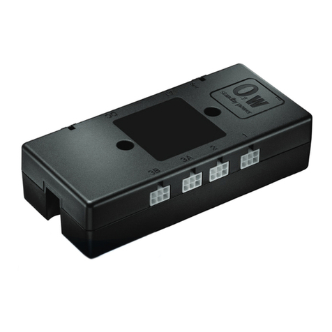
Linak Homeline LA10 User manual

LA10 system
User Manual

LA10 system | 2
Contents
Preface ������������������������������������������������������������������������������������������������������������������������������������������ 3
Important information ������������������������������������������������������������������������������������������������������������������� 5
Safety instruction��������������������������������������������������������������������������������������������������������������������������� 5
General ������������������������������������������������������������������������������������������������������������������������������������� 5
Safety issues ������������������������������������������������������������������������������������������������������������������������������ 5
Before installation, re-installation, or troubleshooting����������������������������������������������������������������� 6
Before start-up �������������������������������������������������������������������������������������������������������������������������� 6
During operation ����������������������������������������������������������������������������������������������������������������������� 6
Misc� ����������������������������������������������������������������������������������������������������������������������������������������� 6
Only for EU markets������������������������������������������������������������������������������������������������������������������� 6
Only for Non EU markets ����������������������������������������������������������������������������������������������������������� 6
Misuse��������������������������������������������������������������������������������������������������������������������������������������� 6
Declarations����������������������������������������������������������������������������������������������������������������������������������� 7
Manufacturer’s declaration �������������������������������������������������������������������������������������������������������� 7
EU Declaration of Conformity ���������������������������������������������������������������������������������������������������� 8
UK Declaration of Conformity���������������������������������������������������������������������������������������������������� 9
Description of the HOMELINE®LA10 system��������������������������������������������������������������������������������� 10
Maintenance�������������������������������������������������������������������������������������������������������������������������������� 10
Installation����������������������������������������������������������������������������������������������������������������������������������� 11
Connecting the LA10 system with BLE2DC ������������������������������������������������������������������������������ 12
Connecting the LA10 system with BA002�������������������������������������������������������������������������������� 14
Mounting the BA002��������������������������������������������������������������������������������������������������������������� 16
Audio indication overview�������������������������������������������������������������������������������������������������������� 16
Charging the BA002���������������������������������������������������������������������������������������������������������������� 17
Mounting the Charging Point CP002/CP003���������������������������������������������������������������������������� 17
Mounting the BP10 bracket����������������������������������������������������������������������������������������������������� 18
Pairing the remote������������������������������������������������������������������������������������������������������������������� 19
Initialising the system��������������������������������������������������������������������������������������������������������������� 19
Re-initialising the system���������������������������������������������������������������������������������������������������������� 19
Replacing the battery��������������������������������������������������������������������������������������������������������������� 20
Disposal of LINAK products���������������������������������������������������������������������������������������������������������� 21
LINAK application policy��������������������������������������������������������������������������������������������������������������� 22

LA10 system | 3
Preface
Dear User,
We are delighted that you have chosen a LINAK® product�
LINAK systems are high-tech products based on many years of experience in the manufacture and
development of actuators, electric control boxes, controls, batteries, accessories, and chargers�
This User Manual does not address the end-user� It is intended as a source of information for the equipment
or system manufacturer only, and it will tell you how to install, use and maintain your LINAK electronics�
The manufacturer of the end product has the responsibility to provide a User Manual where relevant safety
information from this manual is passed on to the end user�
We are convinced that your LINAK product/system will give you many years of problem-free operation�
Before our products leave the factory they undergo full function and quality testing� Should you nevertheless
experience problems with your LINAK product/system, you are always welcome to contact your local dealer�
LINAK subsidiaries and some distributors situated all over the world have authorised service centres, which
are always ready to help you�
LINAK provides a warranty on all products�
This warranty, however, is subject to correct use in accordance with the specifications, maintenance being
done correctly, and any repairs being carried out at a service centre, which is authorised to repair LINAK
products�
Changes in installation and use of LINAK products/systems can affect their operation and durability� The
products are only to be opened by authorised personnel�
The User Manual has been written based on our present technical knowledge� LINAK is constantly keeping
the information updated, and we therefore reserve the right to carry out technical modifications�
LINAK A/S

LA10 system | 4
This User Manual is valid for the following products:
(See the first 3 - 5 characters on the label)
Actuators: LA10
Controls: BP11, BP12, and BP13
Charging Point: CP001, CP002, and CP003
Accessory: BLE2DC, BA002
Power supply: SMPS001 or SMPS006

LA10 system | 5
Important information
Important information on LINAK®products can be found under the following headings:
Warnings
Failing to follow these instructions may cause accidents resulting in serious personal injury�
Recommendations
Failing to follow these instructions can result in product damage�
Safety instruction
General
Safe use of the system is possible only when the operating instructions are read completely and the
instructions contained are strictly observed�
Failure to comply with instructions marked with the ”NOTE” symbol may result in serious damage to the
system or one of its components�
It is important for everyone who is to connect, install, or use the systems to have the necessary
information and access to this User Manual� Follow the instructions for mounting – risk of injury if
these instructions are not followed�
The appliance is not intended for use by young children or infirm persons without supervision�
If there is visible damage on the product it must not be installed�
Note that during construction of applications, in which the actuator is to be fitted, there must be no
possibility of personal injury, for example the squeezing of fingers or arms�
Only the power supply type SMPS001 or SMPS006, shall be used with the system (LA10 System)�
The power supply shall not be covered while operating to allow sufficient cooling of this appliance�
The appliance is only to be used with the power supply unit provided with the appliance�
Furthermore take care about the connecting wires from the power supply to the LA10 System, do
not damage this by overrun�
Assure free space for movement of application in both directions to avoid blockade�
Safety issues
The builder of the equipment shall ensure that the use of the component complies with relevant
standards – like the Machine Directive� Care must be taken to avoid squeezing of cables as it can
cause movement of the system!
The SMPS001/006 must not be packed in heat insulating material, but must be placed so that it can
emit waste heat to the surroundings� There are no ventilation holes to consider, the SMPS emits heat
through its surface�
Only the power supply type SMPS001 or SMPS006, or similar suited products meeting the
requirements EN 60335-1, shall be used with the system (LA10 system).

LA10 system | 6
Before installation, re-installation, or troubleshooting
• Stop the actuators
• Pull out the mains plug�
• Relieve the actuators of any loads, which may be released during the work�
Before start-up
• Make sure that the system has been installed as instructed in this User Manual�
• Make sure that the SMPS voltage matches the mains voltage before the system is connected to the
mains�
• System connection� The individual parts must be connected before the SMPS is connected to the mains�
See the User Manual for LINAK actuators, if necessary�
During operation
• If the SMPS makes unusual noise or smells, switch off the mains voltage immediately�
• Take care that the cables are not damaged�
• The products must only be used in an environment, that corresponds to their IP protection�
Misc.
The actuator system has a sound level below 70dB(A) in typical applications�
Updated manuals and declarations can always be found here:
www.linak.com/homeline
Only for EU markets
This appliance can be used by children aged from 8 years and persons with reduced physical,
sensory or mental capabilities or lack of experience and knowledge if they have given supervision or
instruction concerning use of the appliance in a safe way and understand the hazards involved�
Children shall not play with the appliance� Cleaning and user maintenance shall not be made by
children without supervision�
Only for Non EU markets
Persons who do not have the necessary experience or knowledge of the product(s) must not use
the product(s)� Besides, persons with reduced physical, sensory or mental abilities must not use the
product(s), unless they are under surveillance or they have been thoroughly instructed in the use of
the apparatus by a person who is responsible for the safety of these persons�
Moreover, children must be under surveillance to ensure that they do not play with the product�
Misuse
Do not overload the actuators – this can cause danger of personal injury and damage to the system�
Do not use the system in environments other than the intended indoor use�

LA10 system | 7
Declarations
Manufacturer’s declaration
DECLARATION OF INCORPORATION OF PARTLY COMPLETED MACHINERY
2006/42/EC ANNEX II B
LINAK A/S
Smedevænget 8
DK - 6430 Nordborg
Herewith declares that LINAK HOMELINE® products as characterized by the following models and
types:
Control Boxes CB9H, CBH Advanced, CBH Basic
Linear Actuators LA27, LA29, LA31 HOMELINE
Dual Actuators TD3, TD4, TD5
Controls HB10 RF, HB20RF, HB60, HC10, HC10RF, HC20RF, HC40
Accessories Bluetooth Adapter, DC CONNECTOR, LED Lightbox, Lightplug001, Massage
Motor, SMPS001, SMPS001, SMPS002, SMPS006
comply with the following parts of the Machinery Directive 2006/42/EC, ANNEX I, Essential health and
safety requirements relating to the design and construction of machinery:
1.5.1 Electricity supply
The relevant technical documentation is compiled in accordance with part B of Annex VII and that this
documentation or part hereof will be transmitted by post or electronically to a reasoned request by the
national authorities.
This partly completed machinery must not be put into service until the final machinery into
which it is to be incorporated has been declared in conformity with the provisions of the
Machinery Directive 2006/42/EC where appropriate.
Nordborg, 2019-10-21
LINAK A/S
John Kling, B.Sc.E.E.
Regulatory Affairs Manager
Authorized to compile the relevant technical documentation
Original Declaration

LA10 system | 8
EU Declaration of Conformity
EU DECLARATION OF CONFORMITY
LINAK A/S
Smedevænget 8
DK - 6430 Nordborg
hereby declares under our sole responsibility that LINAK Actuator System (LA10) for use in adjustable recliner chairs
for the purpose of raising and lowering the back and foot sections:
With main component (marked with CE)
Control unit: BLE2DC001
And options of
linear Actuator(s):
item number: 10aaabbb00000000-cccde0ffgghij, Where - aaa can be 040 or 060; bbb can be between 25 and 150;
ccc can be between 153 and 278; d can be 1, 2, 3 or 4; e can be 1, 2, 3 or X; f can be 0 or 1; gg can be any
character; h can be 0 or 1; i can be any character and j can be 0 or 1.
Charging point: CP002-0500, CP003-0500 or CP100-0500
Power unit: SMPS001 or SMPS006
Handsets: BP10BL, HC05BL, HC10BL, HC1ABL, HC40BL
complies with the Radio Equipment Directive 2014/53/EU (OJ L 153, 22.5.2014, p. 62–106) according to the
standard:
Art.3.1 (a) Safety:
EN 60335-1:2012 + AC:2014 + A11:2014 + A13:2017 + A1:2019 + A14:2019 + A2:2019 (Harmonized to LVD)
Art.3.1 (a) Health:
EN 62479:2010; (Harmonized to LVD)
EN 62233:2008+AC:2008
Art. 3.1(b) EMC:
ETSI EN 303 446-2 V1.2.1 (2019-10),
ETSI EN 301 489-1 V2.2.3;
ETSI EN 301 489-17 V3.2.4
Art. 3.2 Radio:
ETSI EN 300 328 V2.2.2
Complies with Directive 2011/65/EU of the European Parliament and of the Council of 8 June 2011 on the restriction
of the use of certain hazardous substances in electrical and electronic equipment (OJ L 174, 1.7.2011, p. 88–110)
and Directive 2015/863 (OJ L 137, 4.6.2015, p. 10–12) (amending Annex II to Directive 2011/65/EU) according to the
standard:
EN IEC 63000:2018
Nordborg, 2022-07-01

LA10 system | 9
UK Declaration of Conformity
UK DECLARATION OF CONFORMITY
LINAK A/S
Smedevænget 8
DK - 6430 Nordborg
hereby declares under our sole responsibility that LINAK Actuator System (LA10) for use in adjustable recliner chairs
for the purpose of raising and lowering the back and foot sections:
With main component (marked with CE)
Control unit: BLE2DC001
And options of
linear Actuator(s):
item number: 10aaabbb00000000-cccde0ffgghij, Where - aaa can be 040 or 060; bbb can be between 25 and 150;
ccc can be between 153 and 278; d can be 1, 2, 3 or 4; e can be 1, 2, 3 or X; f can be 0 or 1; gg can be any
character; h can be 0 or 1; i can be any character and j can be 0 or 1.
Charging point: CP002-0500, CP003-0500 or CP100-0500
Power unit: SMPS006
Handsets: BP10BL, HC05BL, HC10BL, HC1ABL, HC40BL
complies with the Radio Equipment Regulations 2017 according to the standard:
Reg. 6(1)(a) Health:
BS EN 62479:2010
Reg. 6(1)(a) Safety:
BS EN 60335-1:2012+A15:2021
Reg. 6(1)(b) EMC:
ETSI EN 303 446-2 V1.2.1 (2019-10),
ETSI EN 301 489-1 V2.2.3;
ETSI EN 301 489-17 V3.2.4
Reg. 6(2) Radio:
ETSI EN 300 328 V2.2.2
Complies with The Restriction of the Use of Certain Hazardous Substances in Electrical and Electronic
Equipment Regulations 2012 according to the standard:
BS EN IEC 63000:2018
Nordborg, 2022-07-01

LA10 system | 10
Description of the HOMELINE®LA10 system
The LA10 system consists of one or more Linear Actuators LA10, a Bluetooth®dongle, a control unit, and
a charging point� The solution is designed for adjustable recliner chairs and meets user requirements for
reduced number of cables in the system� The LA10 actuator is intelligent and automatically detects its
position when connected in serial into a system� A Bluetooth®dongle ensures the wireless connection to the
control unit, which is a wireless control placed in a bracket� To complete the design, the charging point is
available in different versions� The entire system is designed to meet user preferences and to fit the elegant
design of modern living-room furniture� In the newest system, the Battery BA002 offers a powerful solution
without a permanent cable to the application�
An LA10 system consists of:
• LA10 linear actuator
• BLE2DC Bluetooth®dongle
• BP11, BP12, or BP13 control unit
• Bracket for control unit
• Charging Point CP001, CP002, or CP003
• Battery Box BA002
• Switch Mode Power Supply SMPS001 or SMPS006
Maintenance
Clean dust and dirt from the outside of the system at appropriate intervals and inspect for damage and
breaks� Inspect the connections, cables, and plugs, and check for correct functioning as well as fixing points�
The cleaners and disinfectants must not be highly alkaline or acidic (pH value must be 6 to 8).
Configuration
The LA10 actuator can be configured via the LA10 configurator� A number of parameters can be adjusted
such as speed and stroke length�
Settings that are not default values, such as increased speed, will have influence on the product
lifetime, push force etc�
Changes made in the configurator are not tested and we cannot guarantee that the specifications
in the data sheet are met�

LA10 system | 11
Installation
The connection cables between units on the bus (from battery to LA10 and between the LA10 actuators)
should be kept as short as possible – use the recommended 400 mm or 800 mm cables and avoid excess
cable�
This becomes more important when having several PLC units (multiple LA10s) on the bus� If this requirement
is not met, communication may be lost and the movement interrupted�
Recommended cable length between the SMPS and the actuator:
• Min� 1�8 m
• Max� 5 m
Shorter cable:
The system may not work correctly, or it may behave in an unexpected way�
Longer cable:
Voltage drop causing the system to run slower�
In general, a rule of thumb for a multiple-actuator system is that the total cable length after the first unit
must be maximum the same length as the cable length from SMPS to the first unit�
*: LA10, BLE2DC, or BA002
Figure 1 Cable length illustration (valid for up to 4 PLC units - units with micro)
Example:
In a system with a 2�5 m charging cable and a 0�5 m charging point cable (in total 3 m from SMPS to the
first PLC unit), the cable length from the first PLC unit to the last PLC unit must be maximum 3 m�

LA10 system | 12
Connecting the LA10 system with BLE2DC
1� Gather all parts for the LA10/BLE2DC system�
Figure 2 All parts of the LA10/BLE2DC system
2� Plug the Bluetooth plug into one of the actuators�
3� Connect the actuators using the connection cable�

LA10 system | 13
4� Connect the Charging Point CP001/002/003 to one of the actuators and connect the power cable�
5� Connect the power cable to the power supply�

LA10 system | 14
Connecting the LA10 system with BA002
1� Gather all parts for the LA10/BA002 system�
Figure 3 All parts of the LA10/BA002 system
2� Plug one of the connection cables into one of the actuators and connect it to the BA002�
3� Connect the actuators using the other connection cable�

LA10 system | 15
4� Connect the Charging Point CP001/002/003 to one of the actuators and connect the power cable�
5� Connect the power cable to the power supply�

LA10 system | 16
Mounting the BA002
Do not pack the BA002 in heat insulating material� Ensure minimum 20 mm distance to objects
close to the BA002 to allow it to emit heat through its surface to the surroundings�
Without mounting bracket
1� Mount the BA002 using two cable ties�
See Dimensional drawings in the Data Sheet for placement of grooves for the cable ties�
2� Fasten the cable ties around a solid part of the application to fixate the BA002 properly�
With mounting bracket
1� Remove the mounting bracket�
2� Mount the bracket using four screws with a head diameter of 10 mm (8 to 10 mm can be used)�
3� Fasten the mounting screws (max� torque 1 Nm)�
4� Slide the BA002 onto the mounting bracket�
Note:
The surface to which the battery box is mounted should have an evenness better than ±0�5 mm
Audio indication overview
The BA002 has an audio indication system which indicates battery levels, pairing, and charging�
15% left - two buzzes 10% left - three buzzes 5% left - five buzzes
One buzz
When system starts charging
One buzz
When system is paired to hand
control or app.
At capacity below 15%, the audio alarm sounds each time the BA002 is activated.
The audio alarm intensifies with decreased battery capacity.
No buzz without key press, the BA002 only buzzes when the application is in use.
1% = approximately one cycle (system with two actuators)
Charge/pairing
Battery levels

LA10 system | 17
Charging the BA002
The BA002 can be charged via the Switch Mode Power Supply SMPS001 or SMPS006 using a DC cable with
2-poled Mini-Fit plug� LINAK offers various cables with straight plug which can be used (e�g� 0705894-200)�
Notes:
• Charging will not start if the capacity is above 80 %�
• The BA002 has a built-in protection to ensure battery and system lifetime�
• The battery limits the discharge current to approx� 6 A�
• The battery can go into a deep sleep mode� See Deep sleep mode to see what that means and how to
exit this mode�
Transportation by plane is not allowed for batteries that are more than 30 % charged�
Deep sleep mode
The battery is designed to reduce the risk of deep discharge� To make it possible for the battery to be stored
for a long period of time without being discharged, it goes into sleep mode when not used for more than
four weeks�
• All BA002 batteries will be in deep sleep mode during transportation�
LINAK charges the battery to 30%, ready to be transported by aircraft,
and puts it into deep sleep mode.
The battery charge can now last up to 3 years*
while stored and not mounted to a system.
Deep sleep mode
* Only valid if the BA002 is stored between 10 and 40 °C
• To wake the battery up, connect the charging cable�
If already connected, remove the charging cable, wait 60 seconds, and plug it back in�
• When not connected to a system, the BA002 will go in deep sleep mode after 65 minutes�
• When the BA002 is connected to a system, it will go in deep sleep mode when not used for 40 days�
Mounting the Charging Point CP002/CP003
No screws are needed to mount the charging point�
The CP002 requires a hole of 24 mm in diameter and the CP003 a hole of 30 mm in diameter�
1� From the front, simply push the charging point through a hole in the fabric� From the back, click the ring
on and tighten until the charging point is properly fixed�
Figure 4 Front Figure 5 Back

LA10 system | 18
Mounting the BP10 bracket
The remote control BP10 contains a magnet that could affect the function of a medical device (such
as a pacemaker)� Please read the instructions of the medical device and keep a safe distance for safe
use, if required�
The bracket consists of four parts� A screwdriver and four screws are needed for mounting the bracket�
Screw specifications:
Countersunk 45°, flat head, max� ø3�5 mm�
1� Use four screws to mount the main part of the bracket on the recliner�
2� Place the metal plate in the bracket first and then click the plastic top into the bracket�
3� Place the control unit in the bracket�
The control unit is attached to the bracket via a built-in magnet� It can easily be removed from the bracket
and used as a remote hand control�

LA10 system | 19
Pairing the remote
When connecting the system to power, it will automatically be in pairing mode for three minutes� The
pairing mode stops when a paired remote sends a command�
1� Press the two upper buttons of the control unit to pair it with the system�
For BP11: press the ‘up’ and the ‘down’ buttons�
If you need to get the system into pairing mode, unplug the system, wait for 10 seconds, and plug
the power cable back in�
There is no need to initialise the system when setting it up for the first time� You just need to
connect it and pair the control�
Initialising the system
1� Push the “down” button on the control unit for the actuator that must be initialised and drive the
actuator to its inner position�
2� Release the button on the control unit�
If more than one actuator is connected, the same must be done with the other channels by pressing the
matching “down” button on the control unit� The system is now ready for use�
Re-initialising the system
If the system needs to re-initialised, please follow this procedure:
1� Press and hold the “down” button for 10 seconds to make the actuator initialise – the actuator can
now drive outwards�

LA10 system | 20
Replacing the battery
This product contains a coin battery� A coin battery can cause serious internal chemical burns if
swallowed�
The CR2032 battery can be replaced when needed�
1� Press the battery cover down and slide to loosen it�
2� Remove the battery cover�
3� Use a screwdriver to remove the old battery�
4� Insert a new CR2032 battery�
5� Put the battery cover back in place�
Dispose of used batteries immediately� Keep new and used batteries away from children� If you
think batteries might have been swallowed or placed inside any part of the body, seek immediate
medical attention�
Other manuals for Homeline LA10
2
Table of contents
Other Linak Control System manuals