SOUNDTEK ST-106 User manual

Medidor de nivel de sonido
integrador, Clase 1, Tenmars
TN-ST106
Integrating Sound Level Meter
ST-106 CLASS 1
User’s Manual
HB2ST1060000


EN - 1
Contents:
1. SAFETY PRECAUTIONS ......................................................................................................... 3
1.1.Preliminary Description ..................................................................................................... 3
1.2.Note................................................................................................................................... 3
2. PREPARATION FOR USE ....................................................................................................... 4
2.1.Initial.................................................................................................................................. 4
2.2.Supply Voltage .................................................................................................................. 4
2.3.Calibration ......................................................................................................................... 4
2.4.Storage.............................................................................................................................. 4
3. ST-106 INSTRUMENT INSTRUCTIONS.................................................................................. 5
3.1.Instrument Description ...................................................................................................... 5
3.1.1.Controls Description ................................................................................................................... 5
3.2.Operation Instructions ....................................................................................................... 6
3.3.Measurement Mode (Measure) Instruction ....................................................................... 7
3.3.1.Sound Pressure Level Lxyp/ Equivalent Continuous Level Lxeq1s Measurement (Page0) ...... 8
3.3.2.Integrating Measurement (Page1).............................................................................................. 9
3.3.3.Big Font Measurement Manual Optional Item (Page2)............................................................ 10
3.3.4.Explanation............................................................................................................................... 11
3.3.5.Input Interface........................................................................................................................... 12
3.3.6.AC Output Interface.................................................................................................................. 12
3.3.7.DC Output Interface.................................................................................................................. 12
3.4.Acoustic Calibration Mode (Calibration) Instructions....................................................... 13
3.4.1.Operation Main Menu ............................................................................................................... 13
3.4.2.Acoustical Calibration With ST-110.......................................................................................... 14
3.4.3.Direct Input Sensitivity Value.................................................................................................... 15
3.4.4.View Calibration Record ........................................................................................................... 16
3.5.The Microphone Lengthens The Test ............................................................................. 16
4. ST-110 SOUND LEVEL CALIBRATOR’S DESCRIPTION (OPTIONAL) ................................ 17
4.1.Introduction...................................................................................................................... 17
4.2.Equivalent Free-Field ...................................................................................................... 17
4.3.Specifications - Sound Level Calibrator .......................................................................... 18
4.4.Operating Instructions ..................................................................................................... 18
4.5.Calibration And Adjustment............................................................................................. 19
4.6.Battery Replacement....................................................................................................... 19
5. MAINTENANCE ...................................................................................................................... 20
5.1.General Information......................................................................................................... 20
5.2.Battery Replacement....................................................................................................... 20
5.3.Cleaning .......................................................................................................................... 20
5.4.End Of Life ...................................................................................................................... 20
6. TECHNICAL SPECIFICATIONS............................................................................................. 21
6.1.Feature............................................................................................................................ 21
6.1.1.Standard: .................................................................................................................................. 22
6.1.2.General Data ............................................................................................................................ 22
6.2.Environment .................................................................................................................... 22
6.2.1.Environmental Conditions......................................................................................................... 22
6.2.2.EMC.......................................................................................................................................... 23
6.3.Accessories..................................................................................................................... 23
6.3.1.Standard Accessories............................................................................................................... 23
6.3.2.Optional Accessories................................................................................................................ 23
7. SERVICE ................................................................................................................................ 24
7.1.Warranty Conditions........................................................................................................ 24
7.2.Service ............................................................................................................................ 24

EN - 2
EN - 3
1. SAFETY PRECAUTIONS
When taking measurements:
zAvoid doing measurements in humid or wet places - make sure that humidity is within
the limits indicated in section “environmental conditions”.
zAvoid doing measurements in presence of explosive gas, combustible gas, steam or
excessive dust.
The following symbols are used:
Caution: refer to the user’s manual. An incorrect use may damage the tester or
its components
The instrument conforms to the CE standard
1.1. Preliminary Description
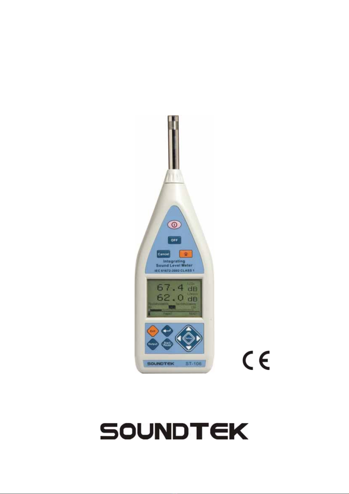
ST-106 is a high performance conforms to international IEC61672 Class 1 Integrating
Sound Level Meter. It may also survey: Lxyi, Lxyp, Lxeq, Lxmax, Lxmin, LAE, Lcpeak,
Lzpeak, three kind of at the same time frequency weighting (A, C, Z) and three kind of at
the same time weighting (F, S, I) may simultaneously survey many kinds of appraisal
target, the dynamic range is bigger than 110dB, it does not need to select the measuring
range when doing measurements, the operation is simple.
Applications: Evaluation of environmental noise, Measurements of noise at workplaces,
Assessment of product noise.
1.2. Note CAUTION
Does not observe the warning and/or operation instruction, it’s possible to
damage the instrument either its components or the operator
zDo not operate the instrument at temperature and humidity environment beyond to
reference conditions of chapter 6.2.1.
zKeep the microphone dry and avoid severe vibration.
zWind blowing across the microphone would bring additional extraneous noise. Once
using the instrument in the presence of wind, it must mount the windscreen to prevent
the undesirable signals. (Refer to Fig. 3)
EN - 4
2. PREPARATION FOR USE
2.1. Initial
The instrument has been checked mechanically and electrically prior to shipment.
Take care to ensure the instrument reaches you undamaged.
However, it is wise to carry out a rapid check in order to detect any possible damage that may
cause during transport. If its damage, claims to the dealer immediately.
Check the packaging content according to packing list reported in 6.3.1chapter .In case of
discrepancies, contact the dealer immediately.
In the event of re-shipment of the instrument please follow the instructions reported in
chapter.
2.2. Supply Voltage
The instrument is powered by batteries (refer to chapter 6.1.2 for details on model, no. and
battery life). When batteries are low, a low battery indication is displayed.
To replace/insert batteries as the instructions indicated in chapter 5.2.
The instrument can also be powered by the external power supply. The external power
supply’s voltage is 4~5V and its maximum output current is 500mA.
CAUTION
If you don’t use the instrument for a long period, please take the batteries out to
prevent eventual acid leakage from damaging the instrument
2.3. Calibration
The instrument complies with the technical specifications contained in this manual and
such compliance is guaranteed for 1 year. The instrument is maybe need recalibration
after one year.
2.4. Storage
After a period of storage in extreme environmental conditions exceeding the limits
mentioned in paragraph 6.2.1 let the instrument return to normal measuring conditions
before using it.
EN - 5
3. ST-106 INSTRUMENT INSTRUCTIONS
3.1. Instrument Description
3.1.1. Controls Description
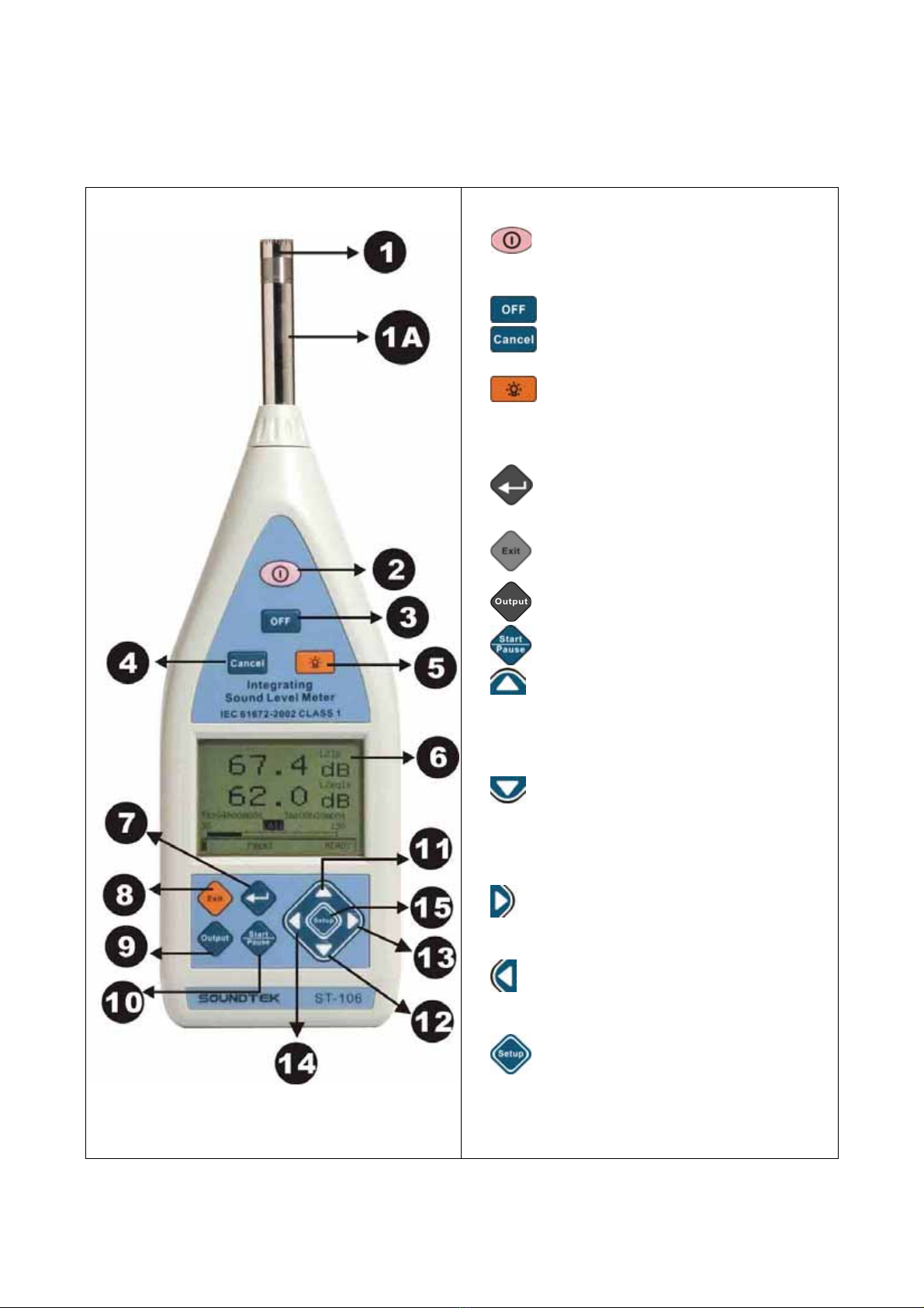
Fig. 1
1. Microphone
1A. Preamplifier.
2. : Turns on the power (press a second
more) or carries on the reset to the
instrument.
3. : Turn off.
4. : Deletes the current measurement
result.
5. : Lightens the backlight, automatic
shut-off after the indicated time delay.
presses again to closes the backlight.
6. LCD display.
7.
: Enters to next or choose
Page0~Page2 or determine the current input.
8.
: Returns to previous menu.
9. : Finished the current measurement.
10. : Starts or pause integral measurement.
11. : The cursor adds 1 in the position
parameter, presses down tightly, the
parameter adds 1 continuously, when comes
to the starting picture, presses this key to
change LCD pale.
12. : The cursor reduces 1 in the position
parameter, presses down tightly, the
parameter reduces 1 continuously, when
comes to the starting picture, presses this
key to change the LCD depth.
13. : The cursor move to right side, or
presses down tightly, cursor continually move
to right side.
14. : The cursor move to left side, or presses
down tightly, cursor continually move to left
side.
15. : Set up backlight auto shut-off time,
when LCD in the starting picture, presses this
key, the LAMP time will be changed from 5
seconds up to 95 seconds.
EN - 6
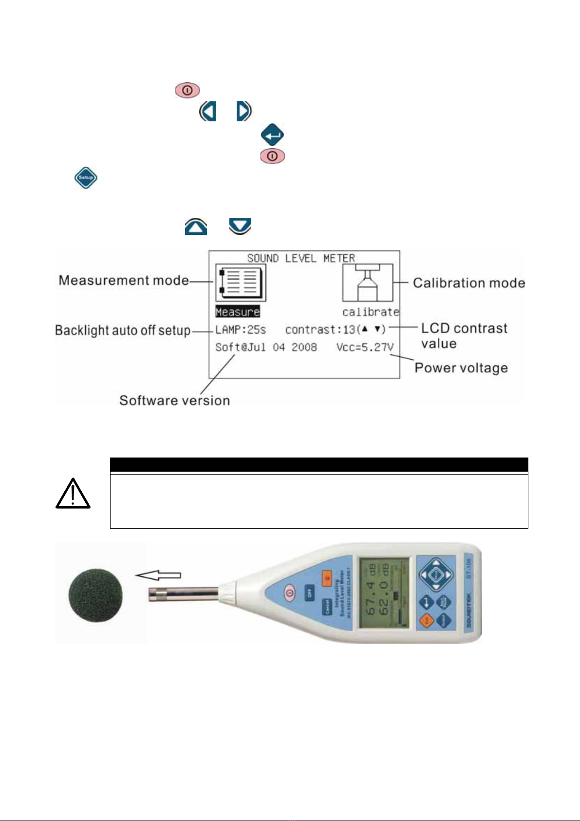
3.2. Operation Instructions
Pressing power button more than a second to start the instrument, enters to initial list
display for mode. Select or key, “Measure” (refer to chapter 3.3) or mode
“Calibrate” (refer to chapter 3.4), press key for making measurement or calibration. If
it’s mistake in selection, may press the key to return to the initial list display. Presses
the key to set up the backlight (5~95 seconds).
zLCD contrast setup:
The user may press and key to setup LCD contrast, the number from 0~25.
Fig. 2
CAUTION
Wind blowing across the microphone would bring additional extraneous noise.
Once using the instrument in the presence of wind with speed higher than
10m/s, it must mount the windscreen to prevent the undesirable signals. Keep
the microphone dry and avoid severe vibration.
Fig. 3
EN - 7
3.3. Measurement Mode (Measure) Instruction
Fig. 4
EN - 8
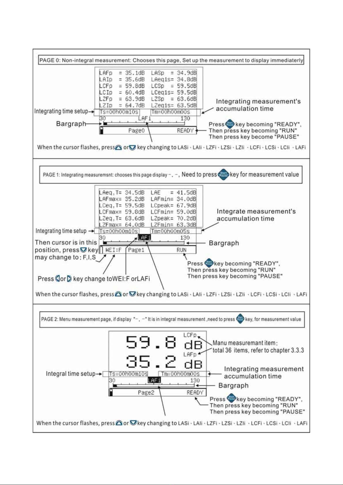
When enters the measurement mode according to chapter 3.2 operations, may press
down the key to change 3 kind of display pages, sound pressure level Page0,
integrating measurement Page1, manual “big font display” measurement mode: Page2,
Total: 3 kind of display modes, and may press the key to watch 3 kind of display
modes repeatedly as necessary, 3 kind of display modes measurement are operate,
simultaneously, including the integrating measurement, when presses down the key,
3 kind of display pages are in integrating measurement simultaneously.
1. Integrating measurement time setup:
"Ts" was the integrating measurement time, "Tm" is the integrating accumulation time.
The user may press down the key to revise the Ts time. If "Ts" is in “00h00m00s”,
the users push to finish it.
2. Integrating measurement start/pause:
The user presses down the key to start the integrating measurement, until the
"Ts” setup time. In the integrating measurement process may manually press down
the key to pause it, in the pause condition, press a key erasing the data if
it’s necessary.
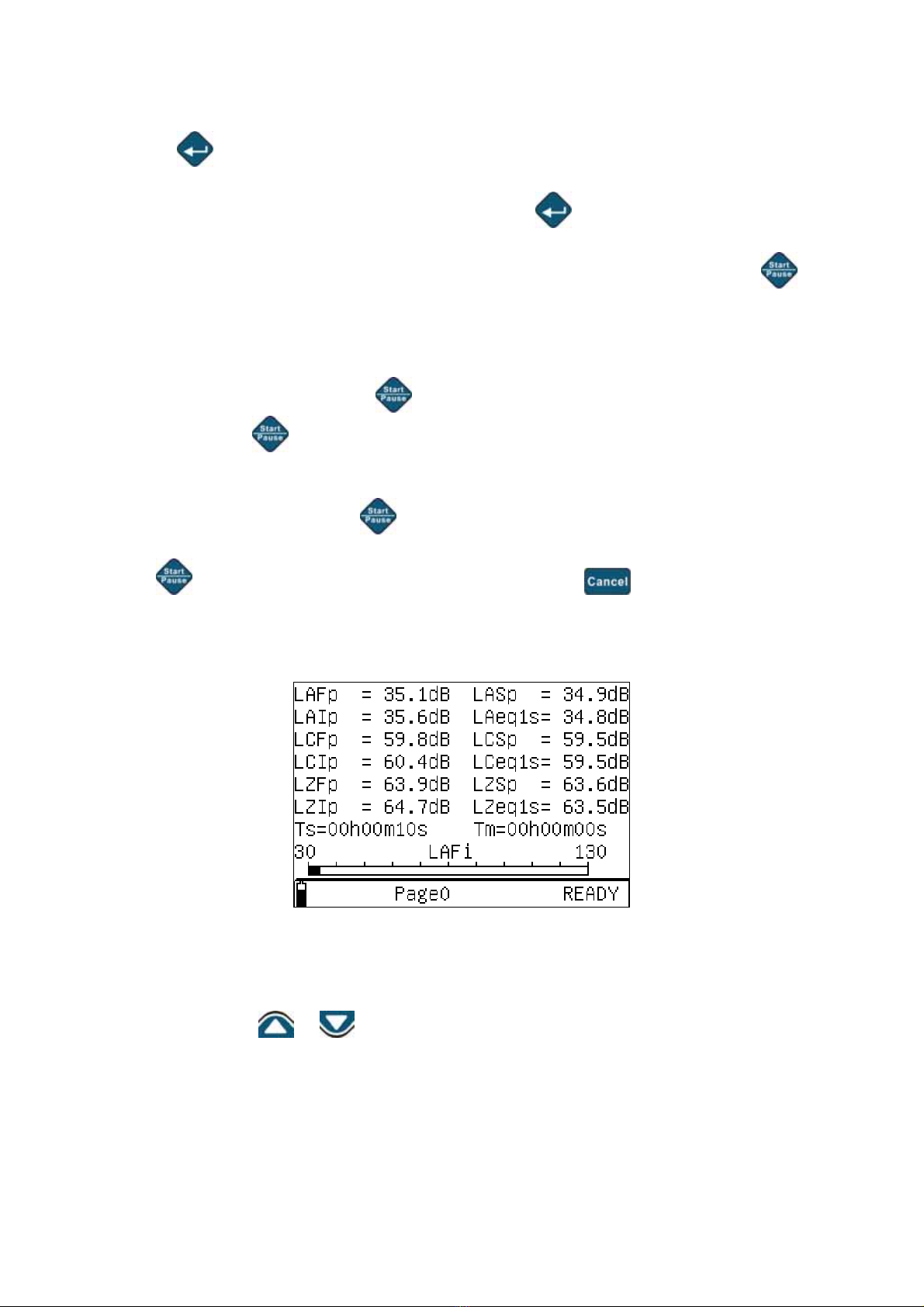
3.3.1. Sound Pressure Level Lxyp/ Equivalent Continuous Level Lxeq1s Measurement (Page0)
Fig. 5
When chooses Page0 LCD displays A, C, Z three kind of frequency weighting, and F, S, I
three kind of time weighting sound pressure level simultaneously. The bottom chart is
bargraph, press the or key, the cursor may change LASi, LAIi, LZFi, LZSi, LZIi,
LCFi, LCSi, LCIi, LAFi. *** Lxyp and Lxeq1s (refer to chapter 3.3.4) ***

EN - 9
3.3.2. Integrating Measurement (Page1)
Fig. 6
1. When chooses Page1 to set up integrating measurement time "Ts" firstly: press the
key, to set up measuring time, (refer to Fig. 6) , the “Ts” integration time is setup,
press key, the integrating measurement can be change from 10 seconds, 1
minute, 5 minutes, 10 minutes, 20 minutes, 30 minutes, 1 hour, 2 hours, 4 hours, 8
hours, 16 hours, 24 hours, manual is the measurement time in “00h00m00s”, when turn
off the power it will automatically store the setting value.
2. LCD display Lxeq, LAE, Lcpeak, Lzpeak, Lxmax, Lxmin simultaneously when set up
the measurement time "Ts", press the key, the instrument starts the integrating
measurement, "RUN" is displayed on the right bottom corner , measurement’s
accumulation "Tm" starts to increase, When the measurement time reaches the setup
time, the measurement will be stopped. In the operation press, presses key, then
measurement is suspended, "PAUSE" is displayed on the right bottom corner, the
integrating measurement time is suspended. If presses key, the current
measurement value will be erased. If press key, then continues to measurement.
(refer to Fig. 6)
3. Under this mode, may press the or key moving the cursor to WEI: presses the
or key changing time weighting F, S, I set again. *** Lxeq, LAE, Lcpeak,
Lzpeak, Lxmax, Lxmin (refer to chapter 3.3.4) ***
EN - 10
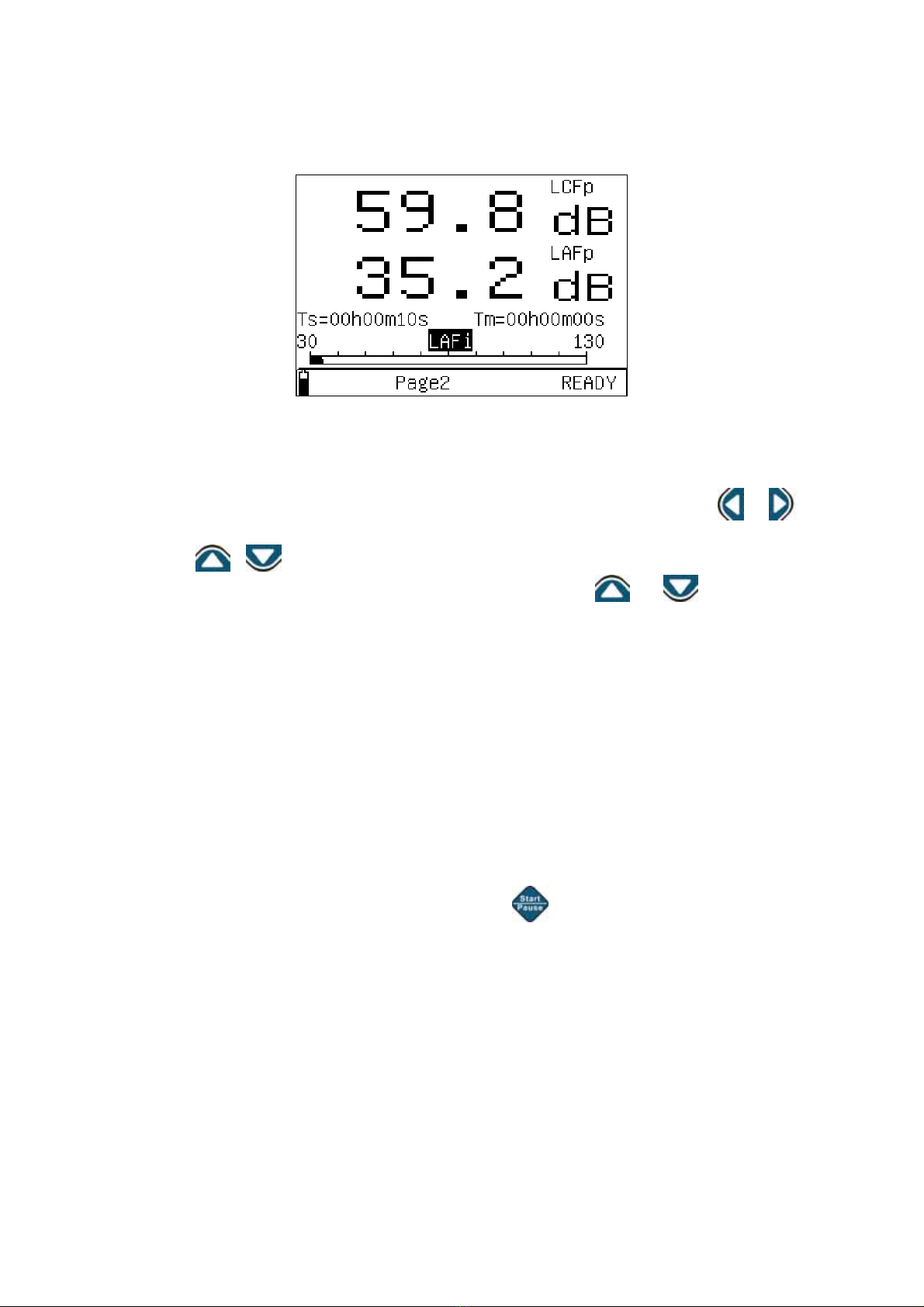
3.3.3. Big Font Measurement Manual Optional Item (Page2)
Fig. 7
1. This mode provides two kinds of big font values, the user may press or key,
the cursor can be changed in "LAFi ", "LCFp", "LAFp". The cursor is in "LAFi" icon,
presses or key to be changes the analog bargraph measuring mode. When
cursor on the "LCFp" or "LAFp" icon, pressing the or key to change
measurement mode.
2. When set up LZFp、LZSp 、LZIp、LCFp、LCFp 、LCIp、LAFp 、LASp、LAIp、
LAeq1s、LCeq1s、LZeq1s,measurement value will be displayed directly.
3. When set up LAeq,T、LCeq,T、LZeq,T、LZFmax、LZFmin、LZSmax、LZSmin、
LZImax 、LZImin 、LCFmax 、LCFmin 、LCSmax 、LCSmin 、LCImax 、LCImin 、
LAFmax、LAFmin、LASmax、LASmin、LAImax、LAImin、LAE、LCpeak、Lzpeakg
For the integrating measurement function, it must start the integrating measurement
function to provide the display value (presses key).If the memory does not save
the previous value, it will display —﹒— 。
EN - 11
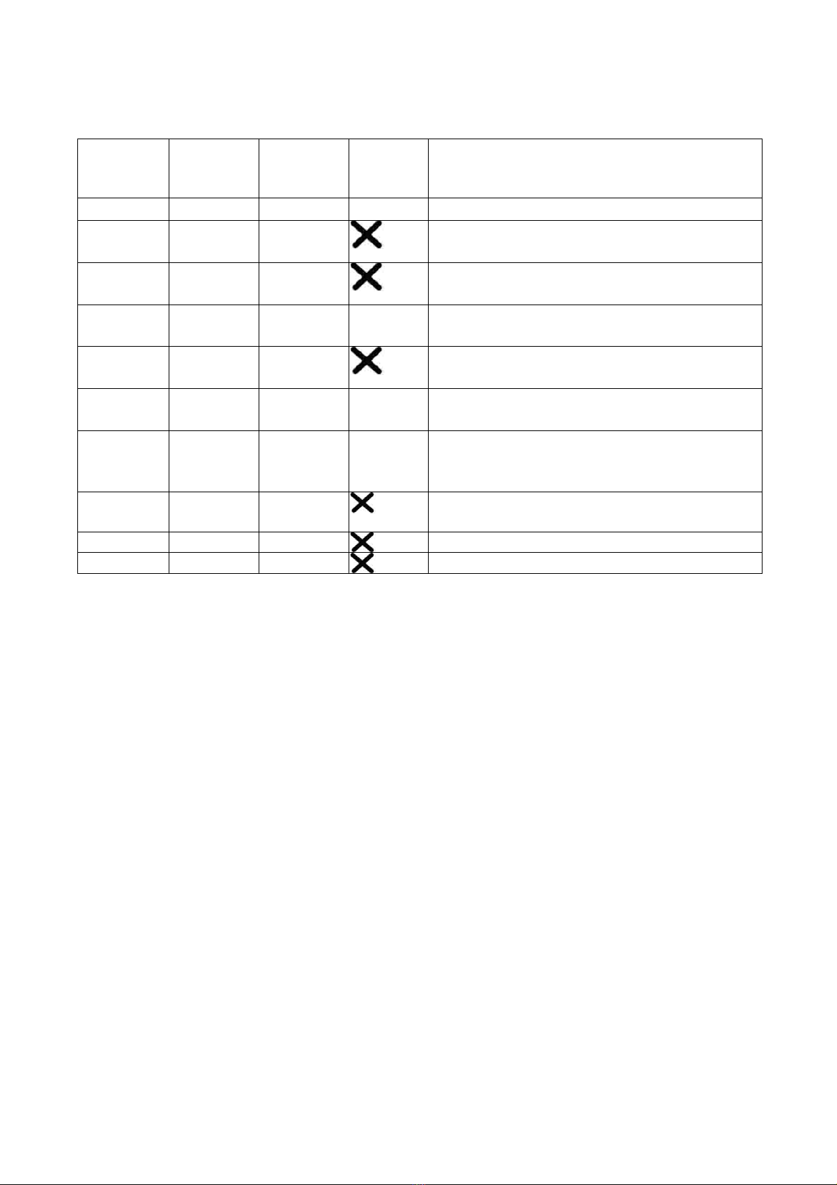
3.3.4. Explanation
1. Measurement Parameters:
Parameter
Default
Screen
parameter
Frequency
Weighting
Time
Weighting
Explanation
Lxyp LAFp A,C,Z
F,S,I Sound pressure level (SPL) (see *2)
Lxeq1s LAeq1s A,C,Z 1 second Xfrequency weighting Equivalent
continuous level. (see *1)
Lxeq,T L
Aeq,T A,C,Z T second Xfrequency weighting Equivalent
continuous level. (see *1)
Lxyi
(Lyons)
LAFi A,C,Z
F,S,I Randomly sampled instantaneous value of
RMS level.(see *2)
Lxeq LAeq A,C,Z Equivalent continuous level for the duration
of the measurement.(see *1)
Lxmax LAFmax A,C,Z F,S,I Max. Lxyp value detected within the
elapsed time.(see *2)
Lxmin LAFmin A,C,Z F,S,I
Min. Lxyp value detected within the elapsed
time.(see *2)
LAE LAE A Frequency weighted sound exposure level
for the duration of the measurement.
Lcpeak Lcpeak C Instantaneous C peak level.
Lzpeak Lzpeak Z Instantaneous Z peak level.
*1︰X is A,C,Z frequency weighting.
*2︰X is A,C,Z frequency weighting.,Y is F,S,I time weighting.
2. A, C, Z Weighting Instruction:
A: The A weighting curve is based on 40 Phon Fletcher-Munson Equal Loudness Contour,
Noise assessment in human, suggest to use the A weighting.
C: The C weighting in essentially is approximate smooth. With labor safety concern,
suggest using the C weighting.
Z: The Z weighting for the electric instrument interior not the linear signal which processes
after the filter, suits in wants to output AC or the DC signal does other research to use.
The Z weighting is a linear signal which is not processed through the filter.
It’s suitable to output AC or DC signal for research.
3. Sound Level Meter Class Description:
zClass 0: use in the laboratory reference standard.
zCass 1: laboratory or field use.
zClass 2: laboratory or field use.
zClass 3: general field use.

EN - 12
3.3.5. Input Interface
The front is X9-6z, the signal input receptacle. The pin definition and function are shown in
Fig. 8:
3.3.6. AC Output Interface
The AC signal output is corresponding to the frequency weighting (Refer to Fig. 9)
Output voltage: 1Pa sound pressure=15mV.
Output impedance: approx. 1kΩ
Load impedance: more than 100kΩ
Load capacitance: less than 100 pF
3.3.7. DC Output Interface
The DC signal’s output is corresponding to the frequency weighting. (Refer to Fig. 9)
Output voltage: Approx. 20mV/dB
DC output is provided by the second PIN of RJ45, the pins definition is shown in Fig. 9,
DC OUT: the output is same as bargraph.
Output pin definition is as following:
Pin number position from right to left (1~8).
Pin 1 is Ground
Pin 2 is Signal
Pin 3~8 null.
Fig. 9
Signal
Ground
Fig. 10
output receptacle 3.5mm output plug
Pin 1 Power supply
Pin 2 Null
Pin 3 Signal input
Pin 4 Null
Pin 5 Signal ground
Pin 6 Null
Fig. 8
EN - 13
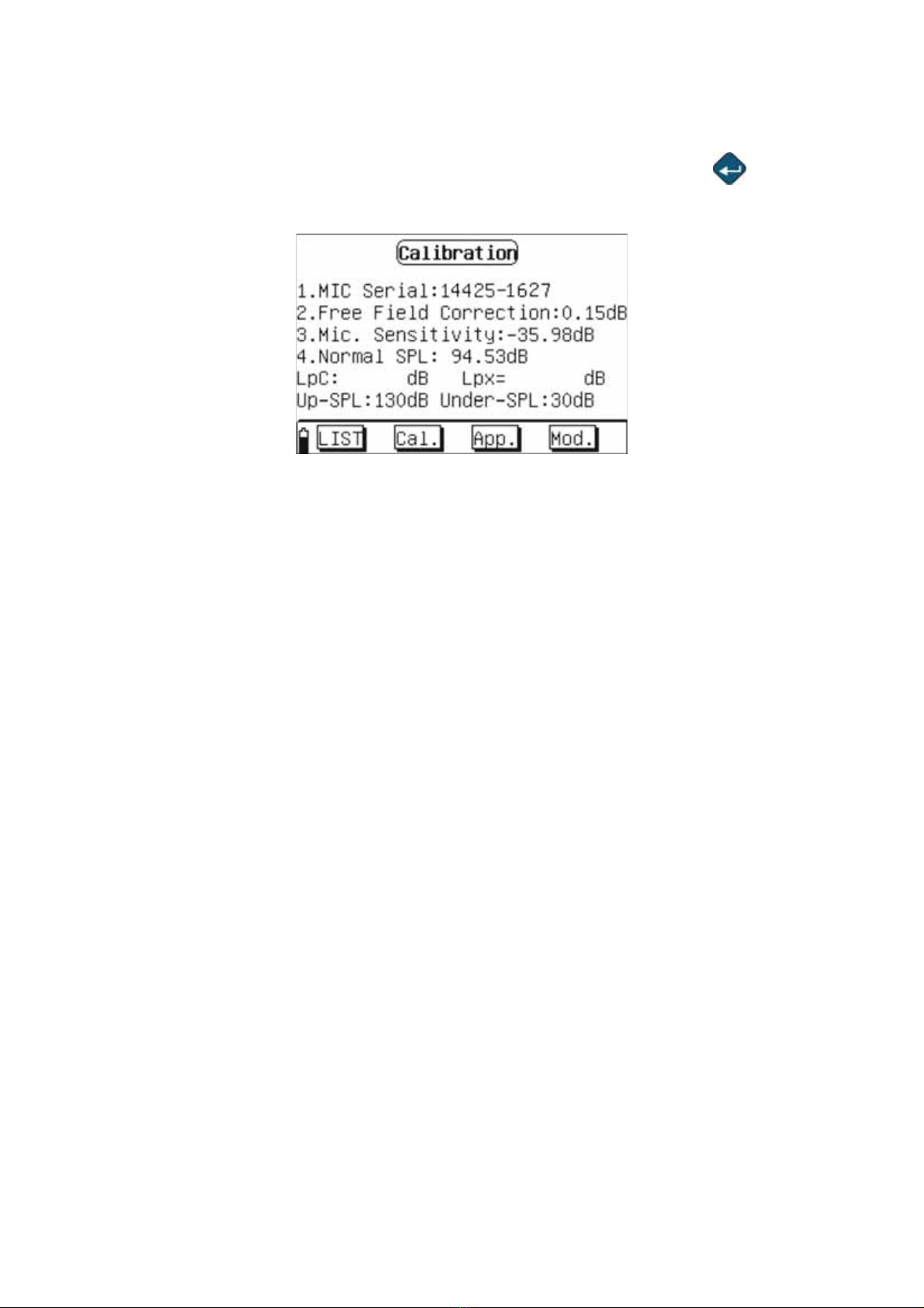
3.4. Acoustic Calibration Mode (Calibration) Instructions
3.4.1. Operation Main Menu
On the main menu,move the cursor to "CALIBRATE" icon and press “ key, it will
display:
Fig. 11
Chart Fig. 11 for entering the adjustment mode main menu; please find the following items
in order:
zItem 1.MIC Serial:
It is the microphone’s serial number, which is set by factory and cannot be modified by
user.
zItem 2.Free Field Correction:
The item 2 is the microphone’s free field correction, which is set according to the
microphone’s type. The ST-106 Sound Level Meter uses 1/2" free field microphone, its
correction between sound pressure field and free field is 0.15 dB at the frequency of 1 kHz.
zItem 3.Mic. Sensitivity:
The item 3 is microphone’s sensitivity level, which is the sensitivity output level of
preamplifier when preamplifier is set on the microphone. The microphone should be
calibrated to get a new sensitivity level when the preamplifier is replaced, as the amplifier
has a certain input capacitance and gain.
zItem 4.Normal SPL:
The Item 4 is calibrator’s sound pressure level, which is the actual sound pressure level
after sound level calibrator is checked.
LpC: when the analyzer is calibrated by C weight.
LpX: indicates the microphone’s current sensitivity level
Up-SPL、Under-SPL: Measuring upper and lower limit.
The last line is the menu, "LIST" button is used to view the calibration records, "Cal" button
is used to start the sound calibration, "App" button is used to store the calibration result
and use the new sensitivity level for the measurement later, "Mod" button allows user to
adjust the free field correction, the microphone sensitivity level and the calibration sound
pressure level.

EN - 14
3.4.2. Acoustical Calibration With ST-110
Fig. 12
1. For the first acoustical calibration, set "calibrator sound pressure level" according to the
calibration certificate of ST-110 Sound Level Calibrator. In general, the sound pressure
level of the sound level calibrator is 94.0 dB, when the measured sound pressure level
is not 94.0 dB, please calibrate it by the actual result, for example, if 94.2 dB, please
modify the item 4. (Normal SPL) value to 94.2dB。Move cursor to "Mod" icon, and
press button,and presses the or key move cursor to the "Item 4 (Normal
SPL) ".
Each presses or , the value increases or reduces 0.01dB.
Continuously presses or the value increases or reduces 1dB.
Move cursor to "App" icon and press key, then microphone’s new sensitivity
level is stored.
CAUTION
The above step is carried only when the indicated calibrator’s sound pressure
is different from that of the working sound level calibrator.
2. Place the ST-110 Sound Level Calibrator on to the microphone, turn the power on and
wait for a few seconds. Move display’s cursor on “ Cal” icon and press key, the
instrument will calibrate automatically. During the calibration, the display’s upper left
side shows a counting number started from 0 when counted to 9 namely the calibration
is completed.
“LpC” indicates the sound pressure level, which is around the result that subtracts the
free correction from the sound pressure level of calibrator.
“LpX” indicates the sensitivity level after calibration.
EN - 15
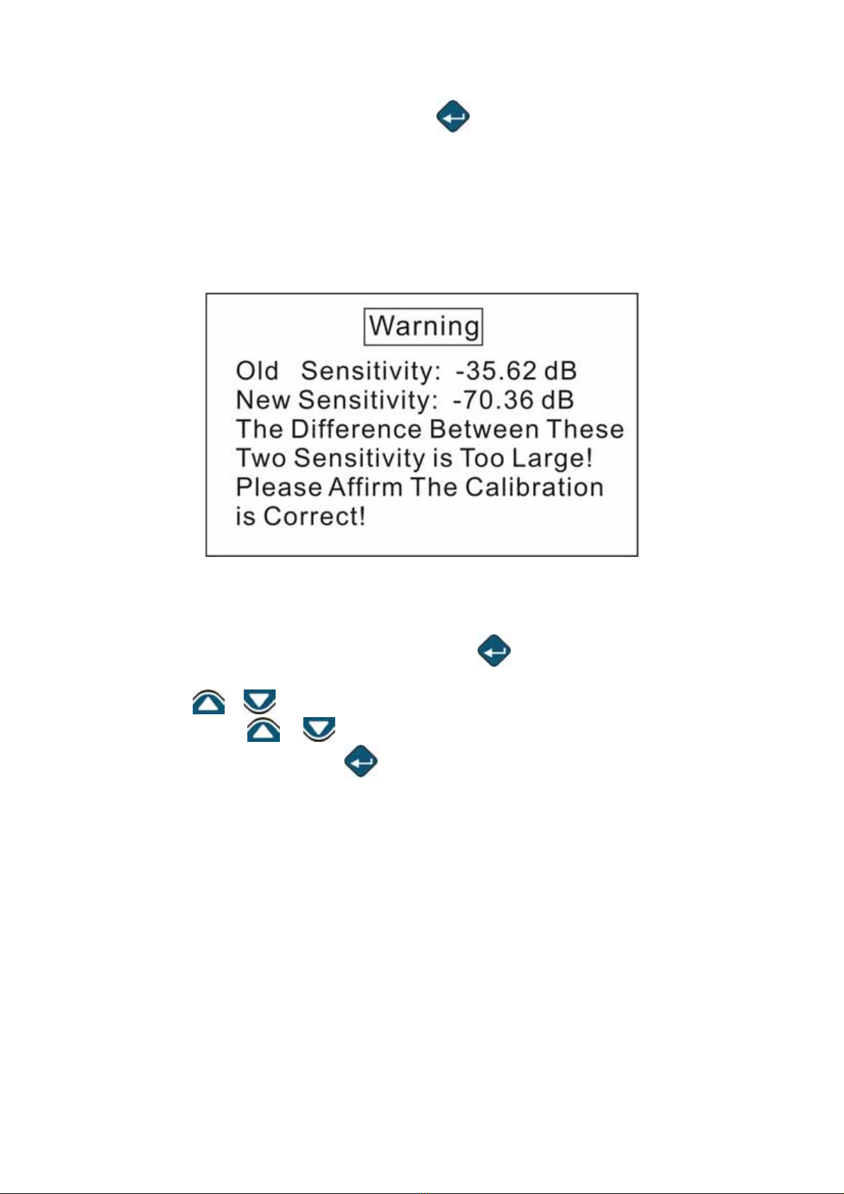
3. Move the cursor to “ App” icon and press key, the microphone’s new sensitivity
level is stored. After the storage, Up-SPL and Under-SPL will be renewed and
displayed the upper and lower limits of the scope after the adjustment.
If the difference is more than 3 dB between the new and stored sensitivity-values, the
instrument will not store the value, and the LCD display prompts “ The Difference
Between These Two Sensitivity Is Too Large! Please affirm the calibration is correct. “.
Please go through the above steps again and confirm the microphone is well-
functioning.
Fig. 13
3.4.3. Direct Input Sensitivity Value
If the user does not has the calibrator,please input the Sound Level Meter’s sensitivity
value directly. Move the cursor to "Mod" icon, press key, then move the cursor to the
project 3.Mic. Sensitivity:
Each presses or , the key value increases or reduces 0.01dB
Continuously presses or the key value increases or reduces 1dB.
Move cursor to "App" button, press key, and then microphone’s new sensitivity level is
stored.
EN - 16
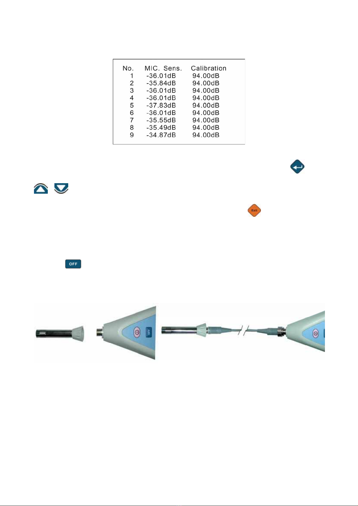
3.4.4. View Calibration Record
Fig. 14
The user can read the calibration record, move cursor to "LIST" icon and press key to
enter the calibration’s record data frame, If the data is more than 9 records, you can press
、to go to the previous or next page. The instrument will store the record each
time; it can save up to 128 records, if save more than 128 records, the instrument will
erase the whole 128 records and only keep the latest one. Press “ ” key to escape this
function.
3.5. The Microphone Lengthens The Test
In order to avoid the measurement deviation caused by the reflection effect and operation
problem, use the cable to extend the microphone for measuring. (Refer to chapter 6.3.2).
1. Press
button to turn the power off.
2. Turn the preamplifier and microphone counterclockwise to be separated from the main
body. (Refer to Fig. 15).
3. Connect the extension cable to the microphone and main body. (Refer to Fig. 16).
Fig. 15
Fig. 16

EN - 17
4. ST-110 SOUND LEVEL CALIBRATOR’S DESCRIPTION (OPTIONAL)
4.1. Introduction
The ST-110, Sound Level Calibrator, is used for the calibration of the pressure sensitivity
of the microphone and sound level measuring equipment. The design of ST-110 is based
on a feedback arrangement to ensure a high stable sound pressure level. The
performance is very stable; it does not required for the revision to the microphone
equivalent volume. ST-110 conforms to the standard of IEC60942 (2003) Class 1. (Refer
to Fig. 17)
4.2. Equivalent Free-Field
Usually we use the free-field microphone more than others. For example, when use the
ST-100 to calibrate the sound level meter and other environmental noise measuring
equipments need to revise the pressure-field to the equivalent free-field. The corrected
value is the difference between the pressure-field response and free-field response when
at 1000Hz. The value for the 23.77mm (1 inch) microphone is –0.4dB, and for the 12.7mm
(1/2 inch) microphone is –0.2dB.
Also the equivalent free-field for the 23.77mm (1 inch) microphone is 93.6dB, and for the
12.7mm (1/2 inch) microphone is 93.8dB.
Fig. 17
Table of contents


