SoundWater jWAVE FC100 Manual

SoundWater
Flow Computer
Instruction Guide
A Wall-mounted Flow Computer
that Connects to Cypress
INSTRUCTION GUIDE
SoundWater Flow Computer

Contents
General Information Page
Introduction ...................................................................3
Dimensions....................................................................4
Typical Applications .............................................................5
Installation
Mounting the Flow Computer .....................................................6
Connecting Flowmeter(s) ........................................................6
Connecting Power & Grounding ...................................................7
Connecting Outputs.......................................................... 8–9
Programming
Setting Flowmeter Options ..................................................... 10
Setting Display Options ........................................................ 11
Programming Hardware Outputs ................................................ 12
Operation
Displaying Measurements...................................................... 13
Troubleshooting
Problems, Probable Causes, Things to Try ........................................ 14
Table of ContentsSoundWater Technologies, LLC
General Information
SoundWater Advantages
Fast to install, easy to use.
MEASUREMENTS YOU CAN TRUST
Our proprietary SoundWater Reciprocity
Architecture™ prevents zero-flow drift
and eliminates the need for calibration,
resulting in long-term measurement
stability and accuracy.
INCREASES PRODUCTIVITY
Featuring compact lightweight
construction and intuitive apps, our
products reduce installation, training,
and setup —saving you time and money.
MADE IN USA
Locally owned and operated out of
Wenatchee, Washington, our products
are built with American quality and
ingenuity.
WORKS IN TOUGH APPLICATIONS
Our transducers auto-adjust ultrasonic
power output depending upon pipe
and fluid conditions — giving you more
frequent measurements when things get
tough (e.g., corroded pipe or murky fluid).
LONG LIFE / LOW MAINTENANCE
SoundWater products are built to last
using the highest quality materials,
gasketed & double O-ring seals, and
silicone gel to protect electronics.
SERVICE & ACCOUNTABILITY
We establish long-term customer
relationships based on trust and service.
We will respond to your needs and
requests within hours.
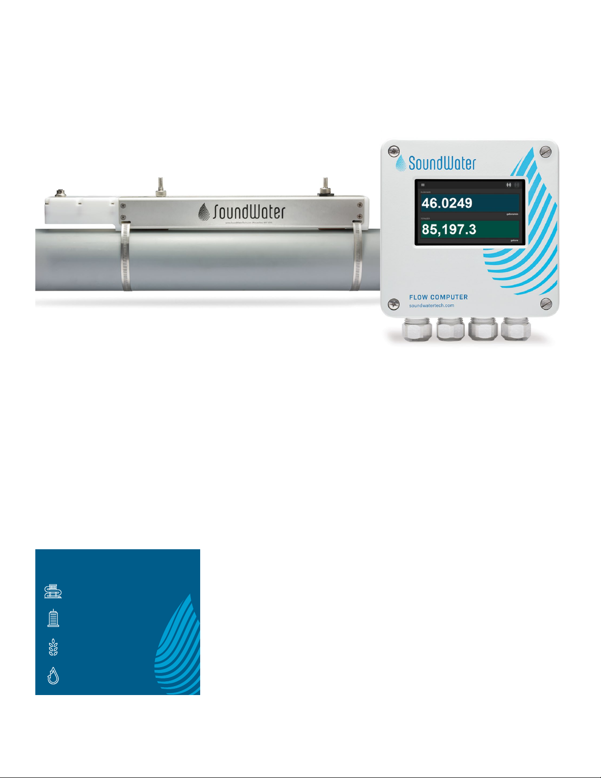
Meet SoundWater Flow Computer.
The SoundWater Flow Computer is a
wall mounted display and computer
that connects to the Cypress
Ultrasonic Flowmeter. It accepts one
or two flowmeters for displaying
measurements, totalizing, averaging
flows, adding or subtracting flows, or
proportional output (dosing/mixing).
It also connects to your SCADA, PLC,
or HMI systems, and is ideal when a
local display is required.
Waterparks, Pools,
and Aquariums
Building Commissioning
and Maintenance
Agricultural
Irrigation
Building Water
Management
Industries
A display and computer for
Cypress Ultrasonic Flowmeters
SoundWater Flow Computer
1-509-899-7838 :: soundwatertech.com

Dimensions
6.53" (16.59 cm) 5.51" (14.0 cm)3.94" (10.0 cm)
6.52"
(16.56 cm) 4.33"
(11.0 cm)
Intuitive Touchscreen Display
The built-in touchscreen is your access to the Flow Computer App featuring a familiar
user experience similar to our Cypress and Orcas mobile apps. Swipe, tap, scroll, and
(if needed) use an on-screen keyboard to specify parameters. The display is backlit
for maximum visibility in darkness or sunlight.
Preset menus, plain-language dialogs, and intuitive navigation let you easily choose
from pre-loaded settings. There is little to no programming setup required: simply
connect power and your Cypress flowmeter, and in seconds the SoundWater Flow
Computer displays flow measurements in English or metric units.
General Information
Flowmeters
• Fully isolated (1.5kV transient; 50VRMS)
• Multiple TVS protection on output
– Common mode ESD
– Series protector on data lines
– Differential varistor
Pulse/Alarm:
• Non-isolated
• Common mode ESD
• Series protector & short circuit protection
Modbus
• Analog low pass filter to suppress high frequency interference
such as static or RFI
• Digital non-linear filter to suppress out-of-band frequencies and
mis-timed transitions
• Fully isolated (1.5kV transient; 50VRMS)
• Multiple TVS protection on output:
– Common mode ESD
– Series protector on data lines
– Differential varistor
4-20mA
• Fully isolated (1.5kV transient; 50VRMS)
• TVS protection
Designed to Withstand Tough Electrical Environments
The Flow Computer was designed with electrical isolation
and protection to operate in electrically noisy environments.
Typical industrial environments with high power, pumps,
VFDs and other large machinery often radiate EMF and
conduct emissions through pipe and wires that can
damage electronics and/or corrupt ultrasound or data
communications. The Flow Computer was fitted with the
electrical isolations and protections listed below for robust
operation and protection in noisy environments:
SoundWater Technologies, LLC
A
B
C
Flow C = A+B
A
B
C
Flow C = A/B
A
B
C
Flow C = Avg(A,B)
Temperature
Basic Setup
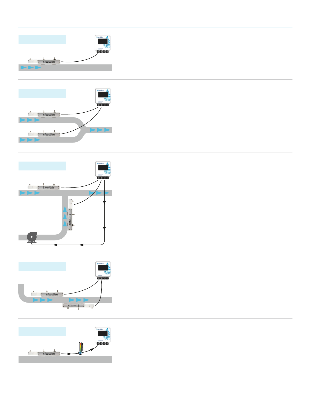
Typical Applications
Proportional Pump Control
For mixing and dosing applications, one flow feeds into another flow to
produce a controlled proportional mixture. In this case the Flow Computer
can be configured to divide one flow by another and display the proportions.
In addition, that proportional flow can be output from the Flow Computer’s
hardware outputs (4-20mA, pulse, Modbus) as feedback to control a pump
and accurately regulate the dosed/mixed proportions.
Converging or Diverging Flows
When two pipes converge into one and the combined flow is desired,
the Flow Computer can be configured to show the total flow (A + B, which
equals C) on the display.
Basic Setup
Connect the Flow Computer to a single flowmeter — whether it's nearby
or thousands of feet away. Display flow rate, total volume, and even fluid
temperature (see details below).
Increased Accuracy or Limited Straight Pipe
Need more accuracy? Don't have enough straight pipe? We have a solution:
install two flowmeters on one pipe, connect them to the Flow Computer and
select to average the two flows. The addition of the second flowmeter adds
another ultrasonic beam into the fluid to sample more of the fluid cross section
and improves measurement accuracy.
Display Fluid Temperature
Need temperature? Our ultrasonic flowmeters not only measure flow, but they
also use ultrasound to measure fluid temperature inside the pipe! From the Flow
Computer setup menu, simply select to display a temperature measurement, and
from which flowmeter.
NOTE: Temperature measurement for water applications is limited to 32°–176° F (0°– 80°C) and you must
provide the fluid’s static pressure (defaults to 80 psi). If the pressure in your system is relatively stable and
fluid temperature is within the aforementioned range, this may be a great tool for thermal measurement.
General Information1-509-899-7838 :: soundwatertech.com

Connect your Cypress Flowmeter(s).
• Insert flowmeter cord set/cable into strain relief/
cord grip (A).
• Unplug flowmeter terminal block (B) from socket
(pluggable terminal blocks for easier wiring).
• Insert five flowmeter wires into terminals (B) according to
the color specified on the electronics board.
• Plug flowmeter terminal block back into socket
labeled Flowmeter.
• Repeat if using a second flowmeter (use A/B).
• Remove excess wire slack and tighten strain relief nuts (C).
Mount your Flow Computer
First you’ll mount the Flow Computer in any location that’s
convenient for monitoring ease. The Flow Computer can be
mounted near to your flowmeter(s) or thousands of feet away.
Remove faceplate by unscrewing the four corner screws on
the front. Note: the screws do not pull out of the faceplate;
they unscrew from the base and spin freely in the lid so you’ll
never lose them.
Insert fasteners into internal mounting holes.
Hole for screws is /" diameter (screws not included).
A A
C
B B
Installation
InstallationSoundWater Technologies, LLC
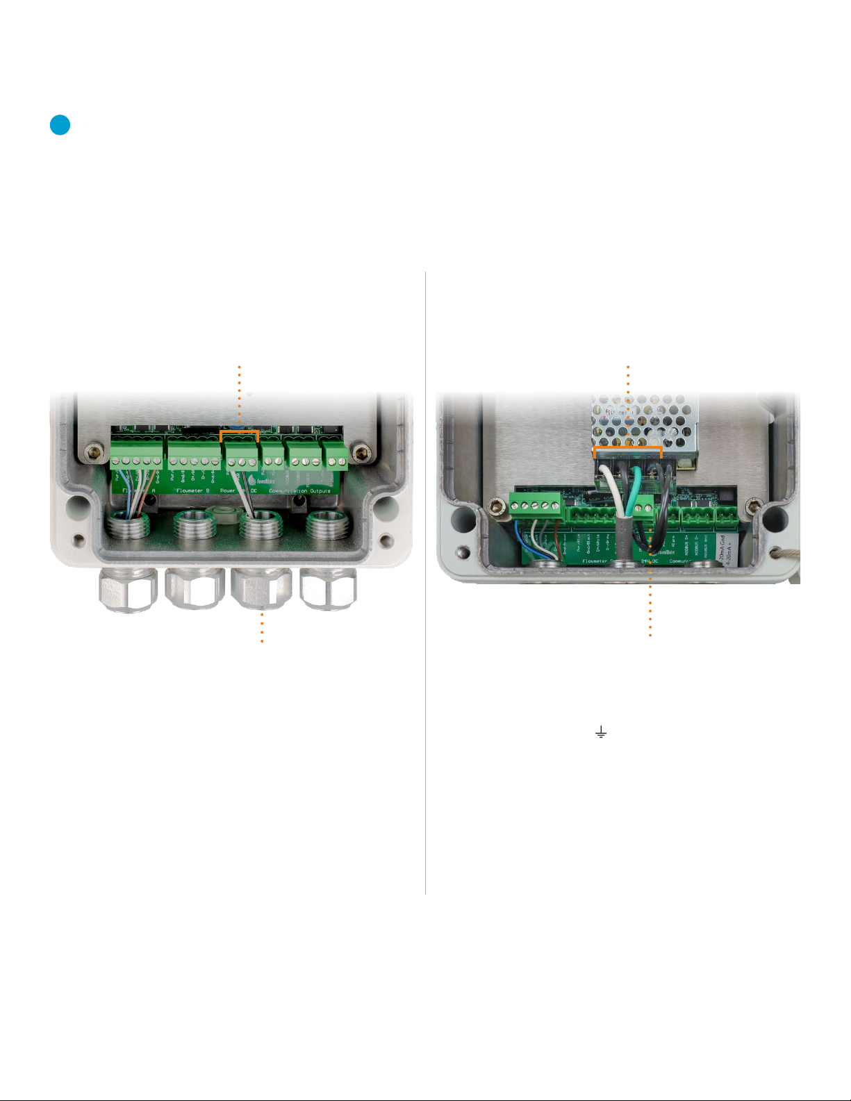
Connect power and grounding
Now that your flowmeters are wired into the unit, it’s time to
connect your power source to the Flow Computer.
Note: A grounding lug is provided for earth grounding and
electrical safety.
Connecting to AC power
(Model FC-AC or FC-AC-AL):
Connecting to DC power
(Model FC or FC-AL):
• Connect hot wire to terminal labeled L(Line),
neutral wire to terminal labled N(Neutral) and ground
wire to terminal labeled (earth ground) on the
AC/DC converter terminal block as shown (A).
• SoundWater already connected the 24 DC output
power to Flow Computer electronics (B).
• Insert power ground, power supply, and earth
ground into strain relief/cord grip (A).
• Remove power terminal block (B) from socket
(pluggable terminal block for easier wiring).
• Connect power to the terminal labeled PWR +
• Connect power ground to the terminal labeled PWR GND
• Connect earth ground to the copper grounding
lug nut. Secure in place with screwdriver.
• Plug the power terminal block back
into the socket labeled Power.
A
AB
B
Installation
Continue to Step 4, next page
1-509-899-7838 :: soundwatertech.com

Connect hardware outputs
Next, connect your preferred outputs (labeled on the circuit
board) using the wiring diagrams provided.
• Unplug desired output terminal block(s)
A= Pulse and/or Alarm
B= Modbus
C= -mA
• For Alarm, Pulse, and 4-20mA, see diagrams below & page 9.
• For Modbus, insert output wires into terminal (B)
according to the labels: Data +, Data –, Optional Shield for
2-wire RS-485.
• Plug output terminal block back into corresponding socket.
• Repeat for additional outputs, if applicable.
• Remove excess wire slack and tighten strain relief nut (D).
User Digital Input Device SoundWater Flow Computer
+ DC power Power Common Ground
Common
Digital input Alarm
+ −
Alarm Output (sourcing input)
Alarm Output (sinking input)
User Digital Input Device SoundWater Flow Computer
Digital input
Power
Alarm
+ DC power
Common Common Ground
+ −
R
5k – 10k ohm (typical)
A B C
D
When you’re finished with all connections, replace cover and fasten lid screws.
Installation SoundWater Technologies, LLC

Pulse Output (sinking input)
-mA Analog Output
User Digital Counter SoundWater Flow Comptuer
Digital input
Power
Pulse
+ DC power
Common Common Ground
+ −
R
5k – 10k ohm (typical)
User Current Input Device SoundWater Flow Computer
Current input 4-20mA Output
0 V 4-20mA Common Ground
User Digital Counter SoundWater Flow Computer
+ DC power Power Common Ground
Common
Digital input Pulse
+ −
Pulse Output (sourcing input)
Installation1-509-899-7838 :: soundwatertech.com

Programming
Apply power
The Flow Computer boots up
in about - seconds and
remains on as long as power
is connected.
Check flowmeter Modbus settings using the Orcas app
Flowmeters are able to communicate with the Flow Computer using their default Modbus
settings. For use with the Flow Computer, do not change these settings. If you have already
changed the Modbus settings, use the Orcas mobile app to connect to your flowmeter(s) and
revert settings to match those shown in the screen shots below.
WARNING: The flowmeter connections at A & B use the same default Modbus settings. Do not
change the Device ID to anything other than the values shown above. The Flow Computer uses
two separate RS- buses, and the slave IDs for both flowmeter A and flowmeter B must be
configured to . Do not change the setup to anything other than the default settings.
Your Flow Computer can be programmed to:
• Display flow measurements from one or more
SoundWater Cypress flowmeters
• Compute analytical combinations of the flowmeter
measurements (for example, flowmeter A + flowmeter B,
flowmeter A – flowmeter B, etc.)
• Communicate with external hardware systems
(4-20mA, Pulse, RS-485 Modbus RTU)
Use the Flow Computer as a local, always-on wall display of
measurements in a fixed setting, or use its advanced features
to calculate the difference of flows in two pipes, average of
flows in two pipes, or control proportional dosing/mixing by
measuring two flows and outputting a proportional pulse or
-mA signal to control pump speed.
And if insufficient straight pipe is available, the Flow
Computer may be used to average two flowmeters to
increase measurement accuracy.
When accuracy is critical, average two flowmeters on the
same pipe—measurement performance typically is improved
by a factor of ..
Save cost by using the Flow Computer to display
measurements from two flowmeters rather than one.
Measure temperature non-invasively (water only). The Flow
Computer and Cypress flowmeter work together to use
ultrasound measurements to infer water temperature.
See Typical Applications on page 5 and program your
devices using the following steps.
Programming Flowmeter(s) & Flow Computer
SoundWater Technologies, LLC
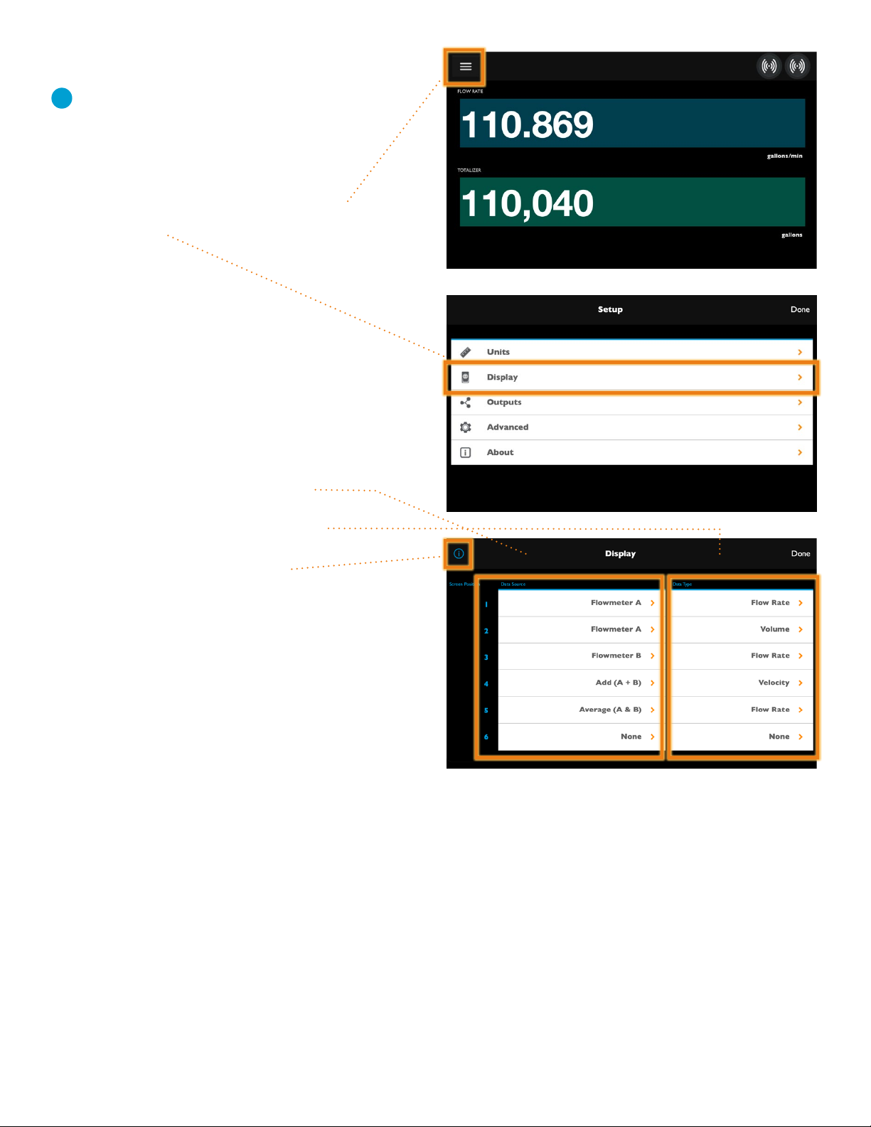
By default, the Flow Computer displays the flow rate
and flow totalizer for flowmeter A.
If you want to display other measurements
and/or display flowmeter B, tap the Menu icon ( )
and select Display.
From the Display menu, for each of the display
fields, tap to choose the source of the data
(Flowmeter A, Flowmeter B, or some combination)
and the type of data (flow rate, totalizer, etc.)
you want your Flow Computer to display.
Tap the help icon ( ) for more detail.
When your preferences are set, tap Done
in the top right corner of the screen and continue
to step , next page.
Choose your display options
Programming
DATA SOURCES DATA TYPES
1-509-899-7838 :: soundwatertech.com
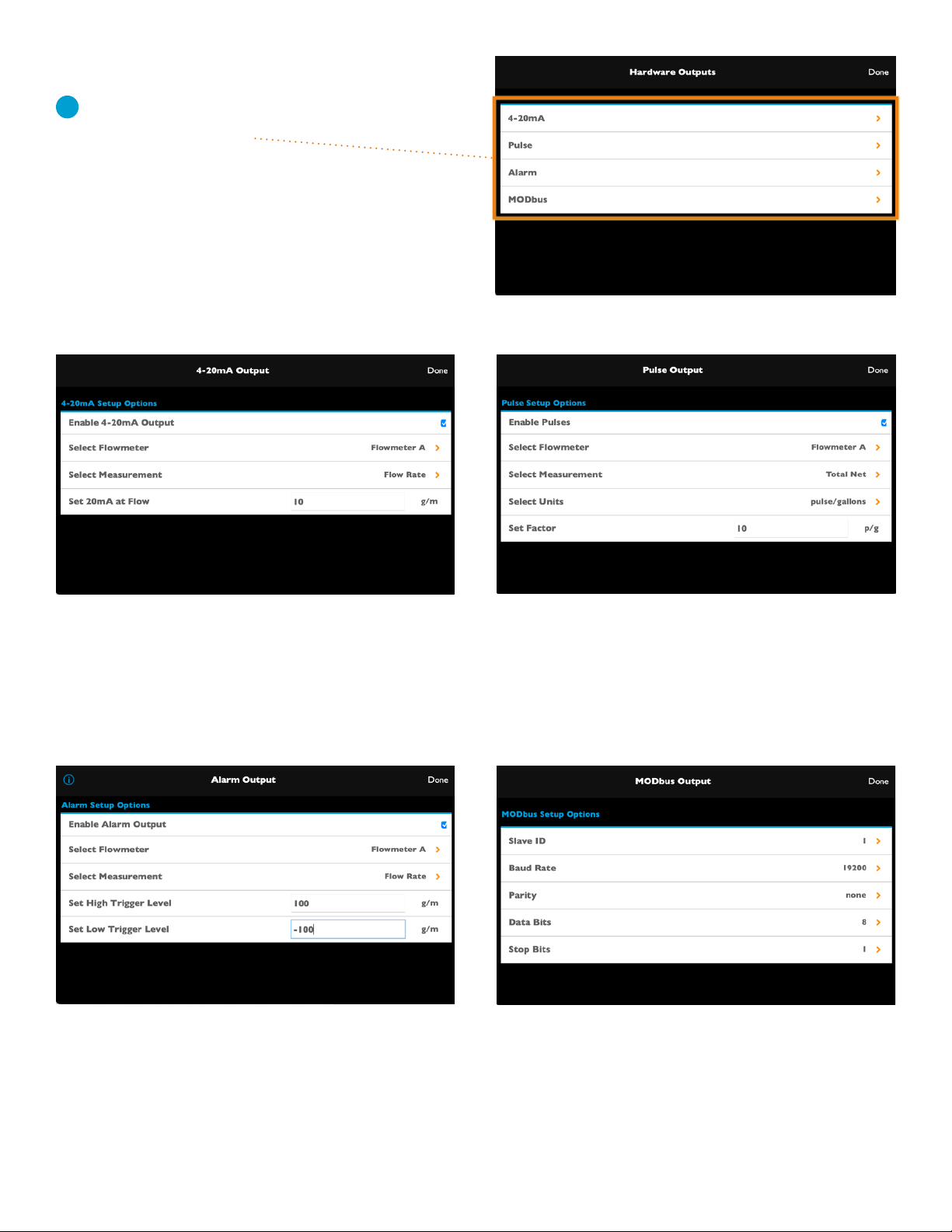
Programming
Modbus Output
You must enter your Modbus port settings
here to match your device.
Program hardware outputs
Choose your hardware output
then follow steps below to program
each output you’ve connected to
your Flow Computer.
Alarm Output
1. Select Flowmeter
2. Select Measurement
3. Set Trigger Levels (high & low)
4-20ma Output
1. Select Flowmeter
2. Select Measurement
3. Select Scaling
PULSE Output
1. Select Flowmeter
2. Select Measurement
3. Select Units
4. Set Factor
SoundWater Technologies, LLC
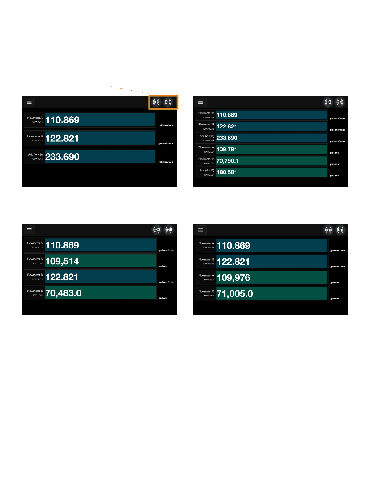
Operation
Start measuring and displaying flow!
Now it’s time to put your flowmeters and SoundWater Flow Computer to work for you. Accurate, real-time flow measurements
and/or flow calculations are at your fingertips.
Display flow rate of two flowmeters and their sum
Ultrasound signal strength indicator for flowmeters A & B
Display the flow rate and totalizer of two flowmeters Rearrange the view of flow rate and totalizer for
two flowmeters
Display flow rate and totalizer of two flowmeters, plus
the sum of both measurements
Display Measurements
1-509-899-7838 :: soundwatertech.com

Problem Probable Causes Things to try…
No information —
only dashes
Incorrect wiring or hardware
programming
Make sure the Flow Computer is wired correctly
following instructions.
If using Modbus, make sure settings match
device.
Air in pipe Rotate meter to 3 o’clock position
Remove air
Relocate meter to another location where
there is no air
Corroded rusty pipe Relocate meter to clean section of pipe. If no
clean section is available, move meter to other
locations until a signal is found—try to find a
section of pipe with less corrosion or rust.
Older steel and ductile iron pipes may be
heavily corroded, which can prevent ultrasound
transfer and flow measurements. For these
types of applications, SoundWater has a special
transducer configuration that helps to penetrate
corrosion, making flow measurement possible.
Please contact us to discuss your application and
how to select the best transducer.
Troubleshooting
Troubleshooting SoundWater Technologies, LLC

1-509-899-7838 :: soundwatertech.com

This manual suits for next models
3
Popular Desktop manuals by other brands

CompuPro
CompuPro 816 Series Service manual

Advantech
Advantech ARK-3380 user manual

Lenovo
Lenovo IdeaCentre B520e Hardware Maintenance Manual

Lenovo
Lenovo ThinkCentre M77 Handboek voor de gebruiker

Interface
Interface Super Classembly Devices mini quick start guide

Commodore
Commodore C-NET 128 v7.0 user manual


