EUROCOM L295U Series User manual

L295U / L297U


Preface
I
Preface
LCD Computer
L295U/L297U Series
Service Manual

Preface
II
Preface
Notice
The company reserves the right to revise this publication or to change its contents without notice. Information contained
herein is for reference only and does not constitute a commitment on the part of the manufacturer or any subsequent ven-
dor. They assume no responsibility or liability for any errors or inaccuracies that may appear in this publication nor are
they in anyway responsible for any loss or damage resulting from the use (or misuse) of this publication.
This publication and any accompanying software may not, in whole or in part, be reproduced, translated, transmitted or
reduced to any machine readable form without prior consent from the vendor, manufacturer or creators of this publica-
tion, except for copies kept by the user for backup purposes.
Brand and product names mentioned in this publication may or may not be copyrights and/or registered trademarks of
their respective companies. They are mentioned for identification purposes only and are not intended as an endorsement
of that product or its manufacturer.
Version 1.0
September 2004
Trademarks
Intel®, Pentium® and Celeron® are US registered trademarks of Intel Corporation.
Windows®is a registered trademark of Microsoft Corporation.
Other brand and product names are trademarks and/or registered trademarks of their respective companies.

Preface
III
Preface
About this Manual
This manual is intended for service personnel who have completed sufficient training to undertake the maintenance and
inspection of personal computers.
It is organized to allow you to look up basic information for servicing and/or upgrading components of the computer.
The following information is included:
Chapter 1, Introduction, provides general information about the location of system elements and their specifications.
Chapter 2, Disassembly, provides step-by-step instructions for disassembling parts and subsystems and how to upgrade
elements of the system.
Appendix A, Part Lists
Appendix B, Schematic Diagrams

Preface
IV
Preface
Related Documents
You may also need to consult the following manual for additional information:
User’s Manual on CD
This describes the computer’s features and the procedures for operating the computer and its ROM-based setup program.
It also describes the installation and operation of the utility programs provided with the computer.

Preface
V
Preface
Contents
Introduction ..............................................1-1
Overview .........................................................................................1-1
Model Differences ...........................................................................1-2
System Specifications L295U/L297U .............................................1-3
External Locator - Front View ........................................................1-6
External Location - Left & Right Side Views .................................1-7
External Locator - Rear View .........................................................1-8
Mainboard Overview - Top .............................................................1-9
Key Parts .........................................................................................1-9
Mainboard Overview - Bottom .....................................................1-10
Key Parts .......................................................................................1-10
Mainboard Overview - Top ...........................................................1-11
Cable Connectors and Switches ....................................................1-11
Mainboard Overview - Bottom .....................................................1-12
Cable Connectors and Switches ....................................................1-12
Disassembly ...............................................2-1
Overview .........................................................................................2-1
Maintenance Tools ..........................................................................2-2
Connections .....................................................................................2-2
Maintenance Precautions .................................................................2-3
Disassembly Steps ...........................................................................2-4
Removing the Hard Disk Drive Assembly ......................................2-5
Removing the LCD Back Cover .....................................................2-6
Removing the System Memory .......................................................2-7
Removing the CPU ..........................................................................2-8
Removing the I/O Bracket .............................................................2-10
Removing the Modem ...................................................................2-11
Removing the Floppy Disk Drive Assembly ................................2-12
Removing the Mini PCI I/F Module .............................................2-13
Removing the CD Device Assembly (L295U Series) .................. 2-14
Removing the CD Device Assembly (L297U Series) .................. 2-15
Part Lists ..................................................A-1
Part List Illustration Location ........................................................ A-2
L295U - Base ................................................................................. A-3
L295U - Back ................................................................................ A-4
L295U - Front ................................................................................ A-5
L295U - Card Reader Module ....................................................... A-6
L295U - Combo ............................................................................. A-7
L295U - Toshiba DVD .................................................................. A-8
L295U - FDD ................................................................................. A-9
L295U - HDD .............................................................................. A-10
L297U - Base ............................................................................... A-11
L297U - Back .............................................................................. A-12
L297U - Front .............................................................................. A-13
L297U - Card Reader Module ..................................................... A-14
L297U - CD-ROM ....................................................................... A-15
L297U - Combo ........................................................................... A-16
L297U - Toshiba DVD-RW ........................................................ A-17
L297U - FDD ............................................................................... A-18
L297U - HDD .............................................................................. A-19
L297U - Video Capture Card Module ......................................... A-20
Schematic Diagrams.................................B-1
System Block Diagram ...................................................................B-2
Northwood - 1 of 2 .........................................................................B-3
Northwood - 2 of 2 .........................................................................B-4
Clock Generator ..............................................................................B-5
MCH Power ....................................................................................B-6
MCH Host .......................................................................................B-7

Preface
VI
Preface
MCH AGP ...................................................................................... B-8
MCH Memory ................................................................................B-9
MCH Memory Termination ......................................................... B-10
DDR RIMM .................................................................................B-11
DVO Chrontel CH7107A .............................................................B-12
LCD Connector ............................................................................ B-13
CRT & USB ................................................................................. B-14
ICH5 (Power, LPC, Clock, SMbus) ............................................. B-15
ICH5 (PCI, IDE, UHB, USB, LAN) ............................................B-16
Thermal & Fan Controller ............................................................B-17
Cardbus PCI1520 .........................................................................B-18
IEEE 1394 .................................................................................... B-19
Cardbus Slot & Mini PCI .............................................................B-20
LAN RTL8100BL ........................................................................B-21
IDE Connector & Firmware Hub .................................................B-22
SIO W83627HF ............................................................................B-23
Serial & Parallel Port ....................................................................B-24
CODEC ........................................................................................B-25
Amplifiers & Inverter Connector .................................................B-26
Power 1 .........................................................................................B-27
Power 2 .........................................................................................B-28
Power 3 .........................................................................................B-29

Introduction
Overview 1 - 1
1.Introduction
1: Introduction
Overview
This manual covers the information you need to service or upgrade the L295U/L297U LCD computer. Information about
operating the computer (e.g. getting started, and the Setup utility) is in the User’s Manual. Information about drivers (e.g.
VGA & audio) is also found in User’s Manual. That manual is shipped with the computer.
Operating systems (e.g. DOS, Windows 9x, Windows NT 4.0, Windows 2000, Windows XP, OS/2 Warp, UNIX, etc.) have
their own manuals as do application software (e.g. word processing and database programs). If you have questions about
those programs, you should consult those manuals.
The L295U/L297U LCD computer is designed to be upgradeable. See “Disassembly” on page 2 - 1 for a detailed de-
scription of the upgrade procedures for each specific component. Please note the warning and safety information indi-
cated by the “” symbol.
The balance of this chapter reviews the computer’s technical specifications and features.
Introduction
1 - 2 Model Differences
1.Introduction
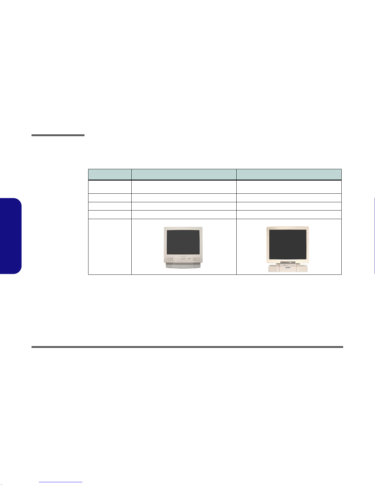
Model Differences
The differences between the model types are indicated in the table and pictures below.
Feature/Model L295U Series L297U Series
LCD Size Color TFT 15" XGA LCD Panel (supporting a resolution
of 1024*768 256K colors) Color TFT 17" SXGA LCD Panel (supporting a
resolution of 1280*1024 16 million colors)
CD Device Location Left Side Front
Dimensions 369mm (H) * 384mm (W) * 188mm (D 395mm (H) * 418mm (W) * 179mm (D)
Weight 8.9 Kg 10.2 Kg
Designs Supported
(Additional Colors
Also supported)
Table 1 - 1
Model
Specifications
Introduction
System Specifications L295U/L297U 1 - 3
1.Introduction
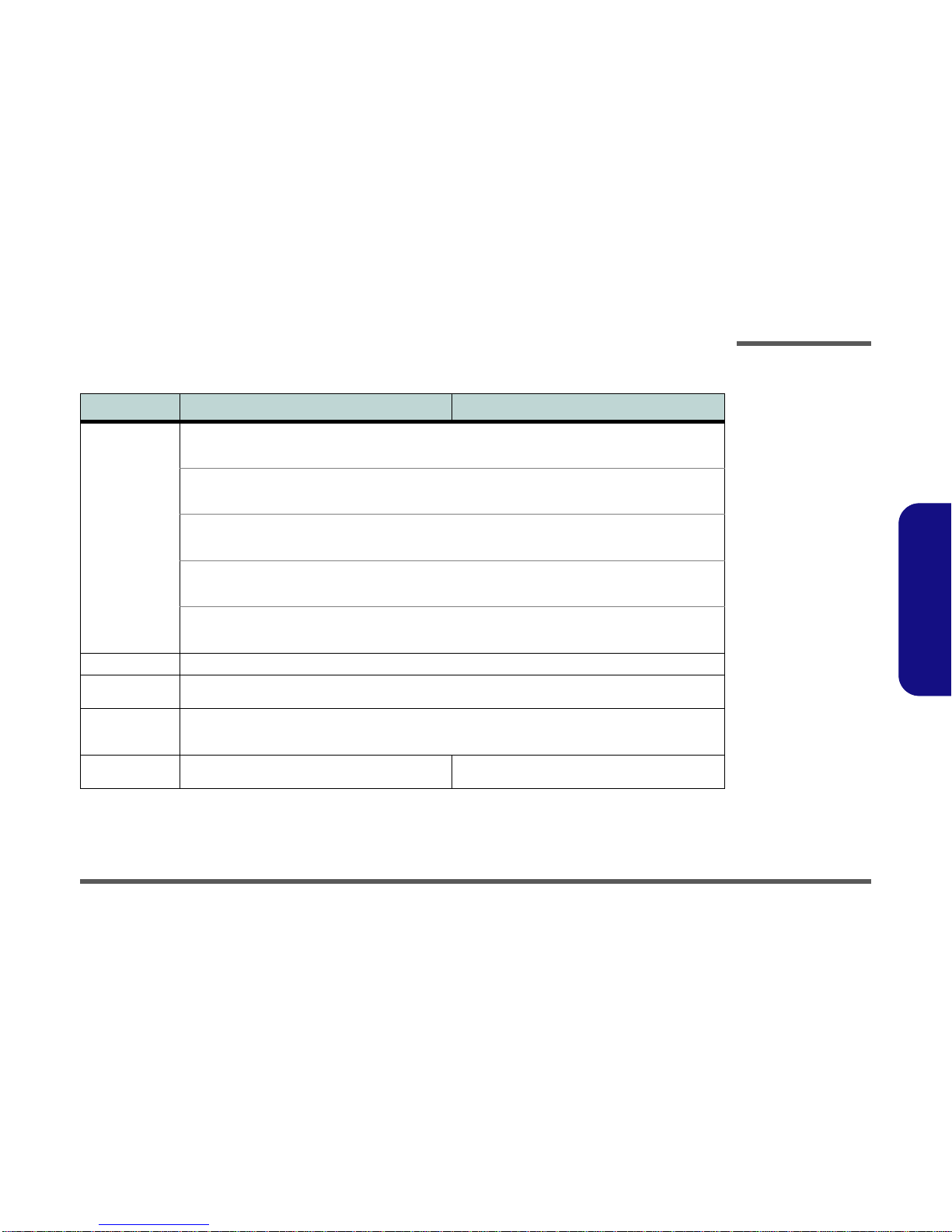
System Specifications L295U/L297U
Feature Specification - L295U Specification - L297U
Processor Types Intel Pentium® 4 with HT Technology (520/ 530/ 540) FC-PGA2 Package (478-pin)
(90nm) - 90 Nanometer Process Technology, 1MB L2 Cache & 800MHz Front Side Bus
2.8/ 3.0/ 3.2/ GHz
Intel Pentium® 4 with HT Technology FC-PGA2 Package (478-pin)
(130nm) - 130 Nanometer Process Technology, 512KB L2 Cache & 800MHz Front Side Bus
2.8/ 3.0/ 3.2 GHz
Intel Pentium® 4 FC-PGA2 Package (478-pin)
(130nm) - 130 Nanometer Process Technology, 512KB L2 Cache & 533MHz Front Side Bus
2.8 GHz
Intel Celeron® D (325/ 330/ 335/ 340/ 345/ 350) FC-PGA2 Package (478-pin)
(90nm) - 90 Nanometer Process Technology, 256KB L2 Cache & 533MHz Front Side Bus
2.53/ 2.66/ 2.80/ 2.93/ 3.06/ 3.2 GHz
Intel Celeron® FC-PGA2 Package (478-pin)
(130nm) - 130 Nanometer Process Technology, 128KB L2 Cache & 400MHz Front Side Bus
2.4/ 2.5/ 2.6/ 2.7/ 2.8 GHz
Core Logic Intel Chipset 865-GV
Memory Two DIMM Sockets Supporting DDR 333/ 400 MHz
Expandable Memory up to 2GB (128M/256M/512M/1GB DDR DIMM modules)
BIOS 4MB Flash ROM Phoenix BIOS
Supports ACPI
Intel OSB Support
LCD Color TFT 15" XGA LCD Panel (supporting a resolution of
1024*768 256K colors) Color TFT 17" SXGA LCD Panel (supporting a resolution
of 1280*1024 16 million colors)
Table 1 - 2
L295U/L297U
System
Specifications
Introduction
1 - 4 System Specifications L295U/L297U
1.Introduction
Video 865-GV Integrated Chipset
Video RAM - Shared Memory Architecture (SMA)
Supporting DDR Video Shared Memory up to 64MB
2D Hardware Accelerator (for block level transfers of data integrating an extensive set of instructions for 3D)
Audio AC97’ Compatible
SoundBlaster™and Windows Sound System™Compatible
Two Built-In Speakers (3W)
Three Audio Jacks for Headphone-Out, Line-In, and Microphone-In
Interface One Serial Port (16550A Compatible, 9 Pin Shell, up to 115Kbps)
One Parallel Port (25pin Shell, SPP/Bi-Direction/ECP/EPP Mode Support)
One External Monitor (VGA) Port (15-pin D-sub)
Two PS/2 Ports (Keyboard & Mouse)
Three Audio Jacks For Headphone-out, Line-in, and Microphone-in
Four USB 2.0 Ports
One RJ-45 Jack for 100M/10M Ethernet LAN
One RJ-11 Port for Modem (optional)
One Mini-PCI /IF IEEE 1394 Module (optional) - Enables IEEE 1394 Port (6 Pin Un-Powered)
I/O Chip Winbond W83627HF
PC Card Sockets Supports Two Type II Slots or One Type III PCMCIA Slot (Cardbus Support)
Feature Specification - L295U Specification - L297U
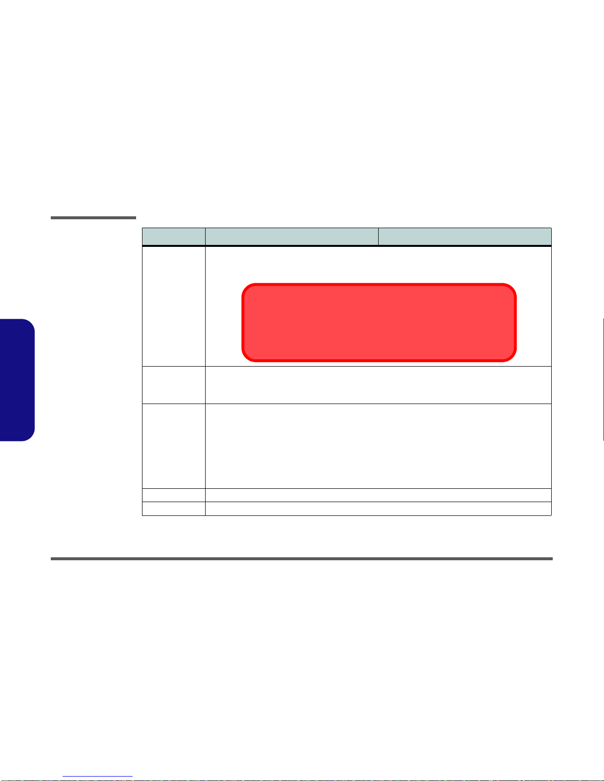
Video Memory
The system allocates or “shares” a portion of system memory for video use. See “Dynamic
Video Memory Technology” on page 3 - 2 for information on the system allocated video
memory, and “Share Memory (Main Menu)” on page 5 - 8 for information on user config-
urable options.
Introduction
System Specifications L295U/L297U 1 - 5
1.Introduction
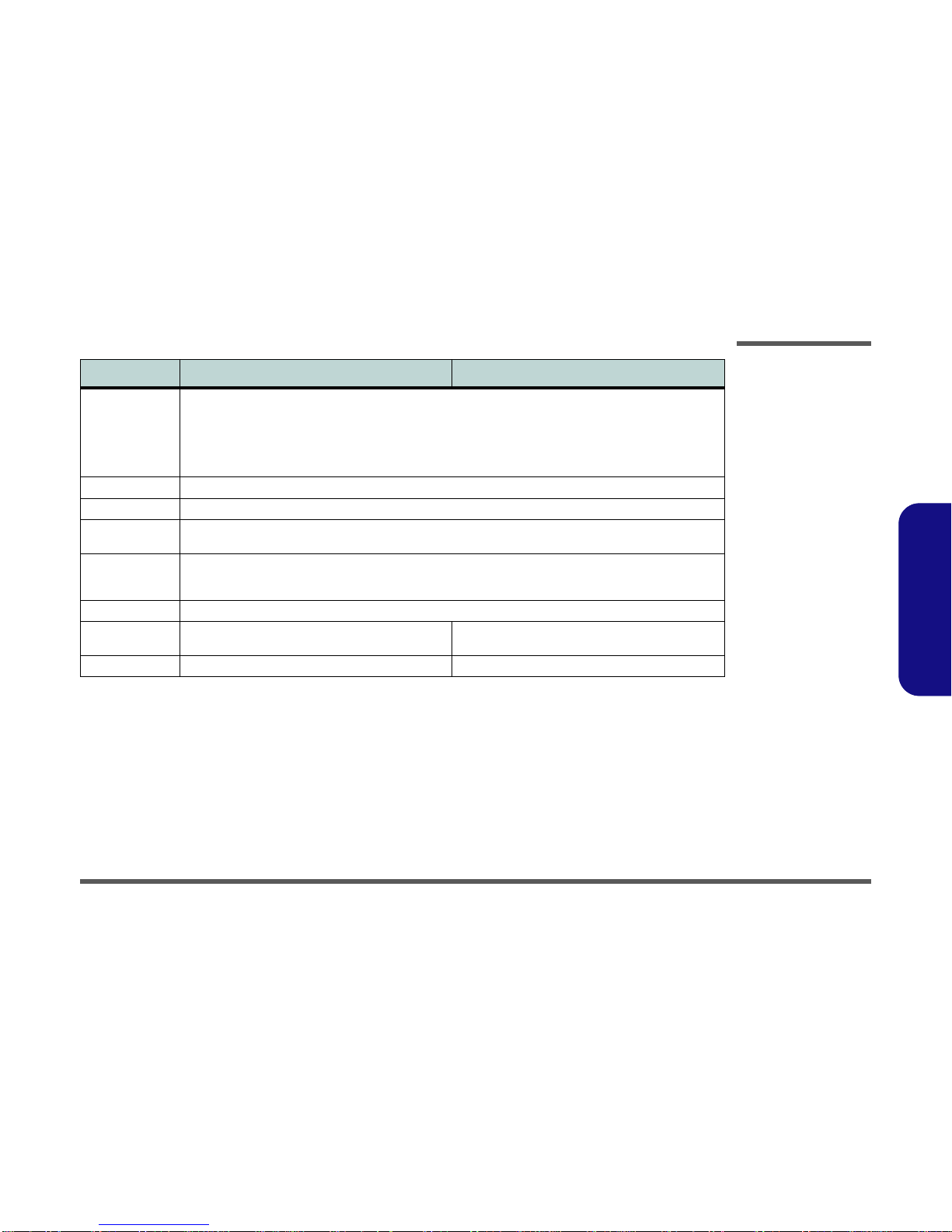
Storage One 3.5", 1.44MB 3-Mode Floppy Disk Drive (Exchangeable With 6-in-1 Card Reader Module or Video-Capture
Module)
One 3.5", 25.4mm Height Hard Disk Drive (Ultra-66/100 I/F Support)
One Optical Device Bay for the Optional 12.7mm Height ATAPI CD-ROM, or CD-RW, or DVD-ROM, or DVD-ROM &
CD-RW Combo, or DVD/RW+R
Modem Removable Internal 56k MDC Data/Fax Modem (optional)
LAN On Board 10/100Mbps Base Auto-Detection
Power Internal Switching Power Supply
Full Range - AC in 90~264V, 160W
Power
Management Supports ACPI
Supports Hibernate Mode
Supports Standby Mode
Indicators LED Indicators (HDD/FDD/CD Device activity, Power)
Physical
Dimensions 369mm (H) * 384mm (W) * 188mm (D) 395mm (H) * 418mm (W) * 179mm (D)
Weight 8.9Kg 10.2Kg
Feature Specification - L295U Specification - L297U
Introduction
1 - 6 External Locator - Front View
1.Introduction
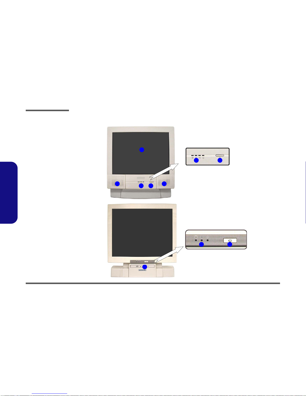
External Locator - Front View
5
1
2
4
23
43
43
L295U Series
L297U Series
L295UT
Figure 1 - 1
Front View
1. LCD Panel
2. Speakers
3. LED Activity
indicators
4. Power Button
5. CD Device
(L297U Only)
Introduction
External Location - Left & Right Side Views 1 - 7
1.Introduction
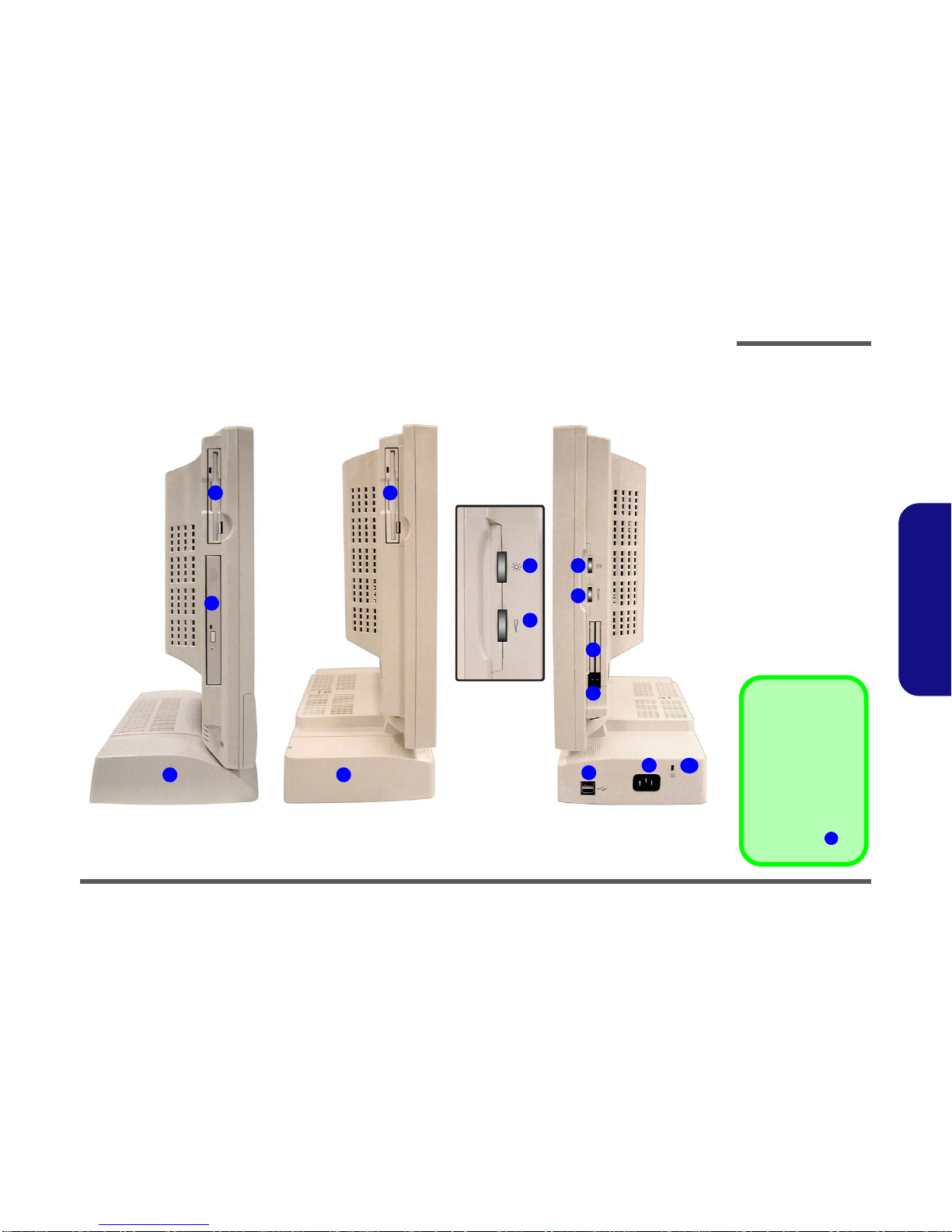
External Location - Left & Right Side Views
*Floppy Disk Drive &
Optional Modules
If you have either the
6-in-1 Card Reader,
or Video Capture
Card options, then
the optional module
will replace the floppy
disk drive module in
the slot at point .
1
Figure 1 - 2
Left & Right Views
1. Floppy Disk
Drive*
2. Hard Disk Drive
(HDD) Bay
3. CD Device
(L295U Only)
4. LCD Brightness
Control Knob
5. Volume Control
Knob
6. Dual PC Card
Slots
7. PC Card Eject
Buttons
8. Dual USB Ports
9. AC Power-In Port
10. Security Lock
Slot
2
7
6
5
4
8
Left
3
Right
9
L295U Series L297U Series
1 1
210
5
4

Introduction
1 - 8 External Locator - Rear View
1.Introduction
External Locator - Rear View
Figure 1 - 3
Rear View
1. Carrying Handle
2. Headphone-Out
Jack
3. Line-In Jack
4. Microphone-In
Jack
5. RJ-45 LAN Jack
6. RJ-11 Phone
Jack
7. Dual USB Ports
8. Unpowered -
IEEE 1394 Port
9. Blocked - IEEE
1394 Port (no
option
installed)
10. PS/2 Mouse &
Keyboard Ports
11. Printer/Parallel
Port
12. Serial Port
13. External Monitor
(CRT) Port
14. Vents
1
4 5 610
14
2 3
9
87
14
11 12 13
14
14 14

Introduction
Mainboard Overview - Top 1 - 9
1.Introduction
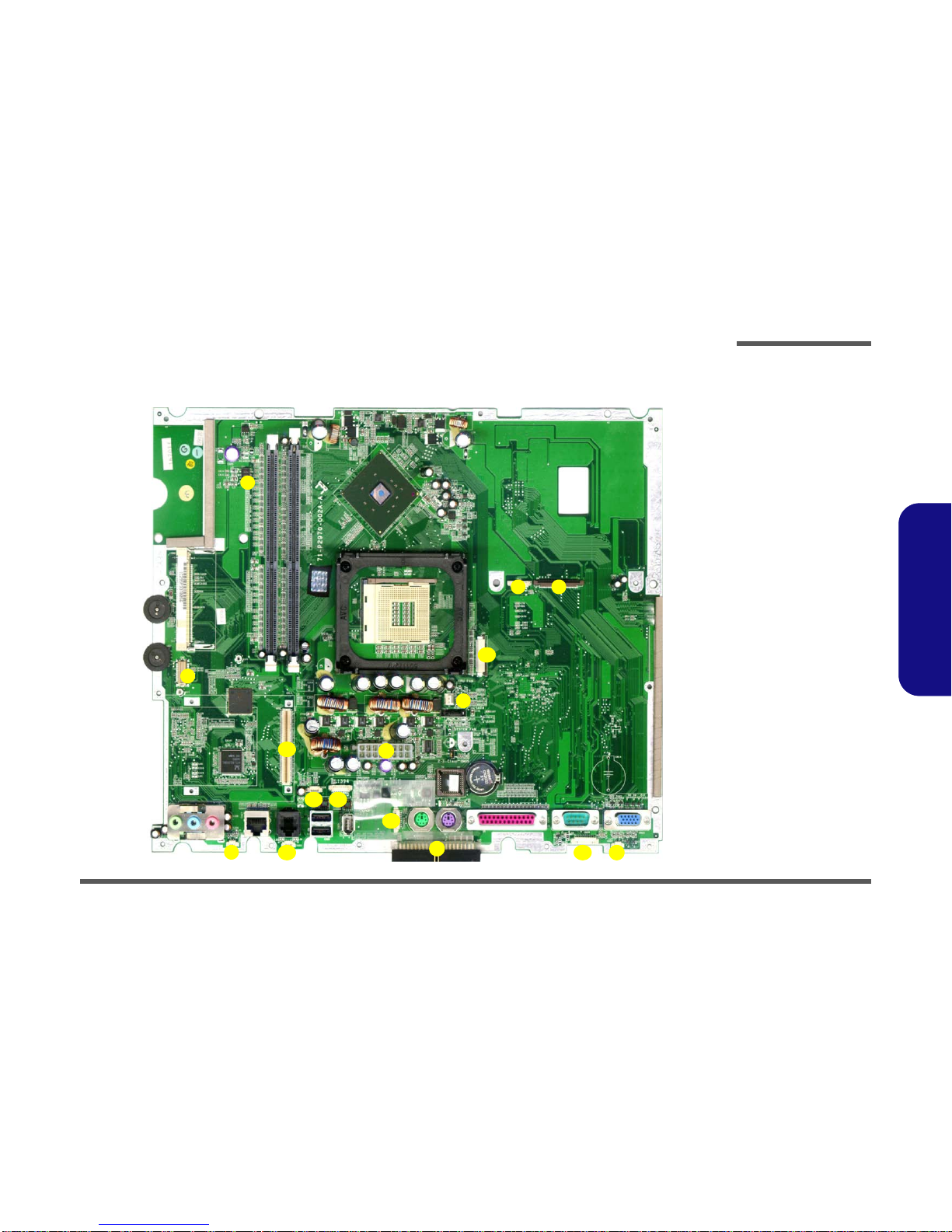
Mainboard Overview - Top
Key Parts Figure 1 - 4
Mainboard
Overview - Top
Key Parts
1. CPU Socket (no
CPU Installed)
2. Intel Springdale-
G (North Bridge)
3. RAM Sockets
4. Mini PCI Socket
for WLAN or
IEEE1394
5. FLASH BIOS
6. CMOS Battery
7. Realtek
RTL8100BL
8. Cardbus
PCI1520
9. CMOS Jumper
Switch
56
7
41
8
32
9
Introduction
1 - 10 Mainboard Overview - Bottom
1.Introduction
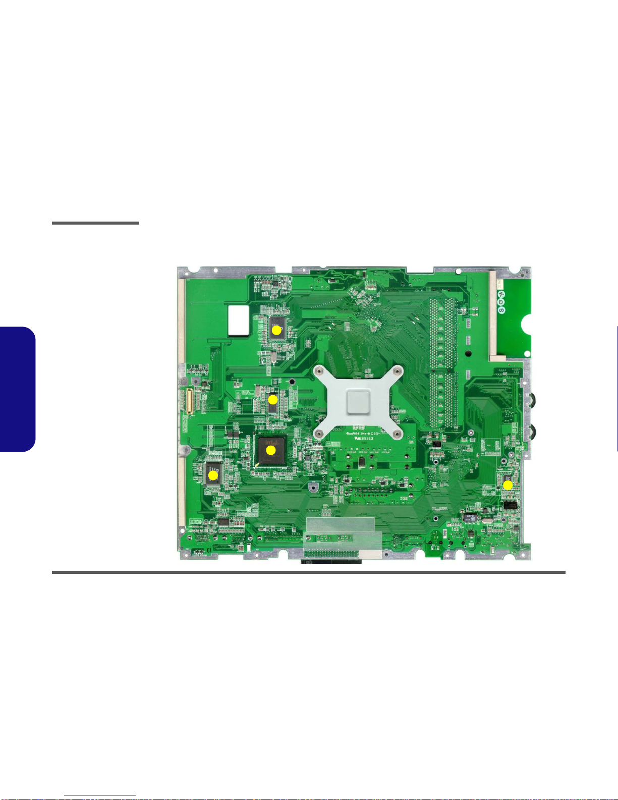
Mainboard Overview - Bottom
Key Parts
Figure 1 - 5
Mainboard
Overview - Bottom
Key Parts
1. Chrontel
CH7017A
2. Clock Generator
3. Intel ICH-5 460
mBGA (South
Bridge)
4. SUPER I/O
Winbond
W83627HF
5. AC’97 MDC
Module
4
5
3
1
2
Introduction
Mainboard Overview - Top 1 - 11
1.Introduction
Mainboard Overview - Top
Cable Connectors and Switches Figure 1 - 6
Mainboard Top
Cable Connectors &
Switches
1. Floppy Disk Drive
(CN5)
2. Card
Reader(CN4)
3. CD/DVD Device
(CN7)
4. Fan Power (CN9)
5. Inverter (CN1)
6. Modem Module
7. Speaker (CN31)
8. Modem Cable
(CN33)
9. PC CARD (CN13)
10. Touch Screen
(CN16)
11. IEEE1394 (CN36)
12. USB 2.0 (CN17)
13. LED Board
(CN30)
14. Speaker (CN32)
15. Power (CN12)
16. Hard Disk (CN34)
1
2
3
4
5
6
78
9
10 11
12
13 14
15
16

Introduction
1 - 12 Mainboard Overview - Bottom
1.Introduction
Mainboard Overview - Bottom
Cable Connectors and Switches
Figure 1 - 7
Mainboard Bottom
CableConnectors &
Switches
1. CN35 (LCD
Connector)
1
This manual suits for next models
1
Table of contents
Other EUROCOM Desktop manuals

EUROCOM
EUROCOM L295P B User manual

EUROCOM
EUROCOM T890M User manual

EUROCOM
EUROCOM A110EU User manual

EUROCOM
EUROCOM LCD PC User manual

EUROCOM
EUROCOM LCD PC User manual

EUROCOM
EUROCOM LP200SC User manual

EUROCOM
EUROCOM Multimedia PC V12.1.00 User manual

EUROCOM
EUROCOM A110SU User manual

EUROCOM
EUROCOM LCD PC User manual

EUROCOM
EUROCOM LP285PB User manual


