South-Tek Systems N2Blast FPS-900 User manual
The Leader in Nitrogen Generation Technology
FPS-900
Fire Protection Systems
O&M Manual
Version 2; 7/2020
© 2020

P
The Leader in Nitrogen Generation Technology
FPS-900 O&M Manual
Revision: 2; 7/2020
Page 2 of 29
TABLE OF CONTENTS:
1. INTRODUCTION…………………………………………………………………………………………. 3
1.1. General Purpose
1.2. About South-Tek Systems
1.3. Audience
1.4. Important Information
1.5. Limits of Liability
1.6. Service Return Policy
2. SAFETY GUIDELINES…………………………………………………………………………………… 5
2.1. General
3. RECEIVING, UNPACKING, AND STORAGE INSTRUCTIONS…………………………………….. 7
3.1. Unpacking and Preparation
4. SITE AND UTILITY REQUIREMENTS…………………………………………………………………. 8
4.1. Air Supply
4.2. Additional Pipings and Hosings
4.3. Electrical Requirements
4.4. Site Specifications
5. PRODUCT INSTALLATION………………………………………………………………………………9
5.1. Mounting
5.2. Installation Arrangement
5.3. Panel Layout and Gas Connections
6. SYSTEM DESIGN…………………………………………………………………………………………13
6.1. Key Features
6.2. Specifications
7. SYSTEM OPERATION……………………………………………………………………………………15
7.1. General
7.2. Normal Run/Standby Mode
7.3. Stopping the System
7.4. Power loss Alarm Mode
7.5. Bypass Alarm
7.6. BlastOff®Alarm (Optional)
7.7. Communication
8. START-UP PROCEDURES………………………………………………………………………………20
8.1. Start-Up Procedures
8.2. Checking for Leaks
9. SYSTEM MAINTENANCE……………………………………………………………………………….. 22
9.1. Air Pre-Filter
9.2. Air Filter Replacement
10. KEY CONTACTS…………………………………………………………………………………………. 24
11. FAQs……………………………………………………………………………………………………….. 25
11.1. Power Issues
11.2. Pressure Issues
11.3. Gas Leaks
APPENDIX A: Advanced Options………………………………………………………………………….. 26
APPENDIX B: WARRANTY………………………………………………………………………………….. 29

P
The Leader in Nitrogen Generation Technology
FPS-900 O&M Manual
Revision: 2; 7/2020
Page 3 of 29
1. Introduction
1.1. General Purpose
This manual provides proper installation and use of South-Tek Systems N2-BLAST
®
FPS-900. South-
Tek Systems is not responsible for damages when using this in manners not approved by South-Tek
Systems. The user(s) of this document should confer any questions with a qualified South-Tek Systems
representative on its commissioning and correct use.
Please contact South-Tek Systems with any question or concerns at:
South-Tek Systems, LLC
3700 U.S. Highway 421 North
Wilmington, NC, 28401
Tel: (888) 526-6284
Email: Info@southteksystems.com
http://www.southteksystems.com/
This document is based upon the R&D performed by the South-Tek Systems Engineering Team.
WARNING: Read the manual in its entirety before installing or using the equipment.
1.2. About South-Tek systems
South-Tek Systems, founded in 1997, is a nitrogen generator manufacturer designing nitrogen
generators for worldwide distribution. Why not produce nitrogen at your facility for a fraction of the cost
versus endlessly paying for bulk liquid or delivered gas cylinders? We make a full line of nitrogen
generator including:
•The N2GEN®Series Nitrogen generators for use in various industrial and lab applications. 50,000
SCFH unit.
•The BeerBlast™ - Mixed Gas Dispense System Increases profits, removes over or under
carbonation, and improves all-around taste and draft beer quality.
•The N2-BLAST
®
- Corrosion Inhibiting System effectively arrests electrochemical, galvanic and
micro-biologically influenced corrosion (MIC) by introducing 98.5% pure nitrogen into dry and pre-
action sprinkler systems.
With purities ranging from 95% up to 99.9995%, we provide nitrogen generators that are sure to suit
your needs. For more information about our complete nitrogen generator capabilities, please visit our
website at www.southteksystems.com.
1.3. Audience
This manual is for Installer/Supervisory Staff. Read the entire manual before operating. Please contact
the local provider for any operation and maintenance questions before contacting the manufacturer.

P
The Leader in Nitrogen Generation Technology
FPS-900 O&M Manual
Revision: 2; 7/2020
Page 4 of 29
1.4. Important Information
All personnel (and their supervisors) installing, operating, and maintaining the N2-BLAST
®
must read
and fully understand this manual prior to installing, operating or performing maintenance.
The N2-BLAST
®
produces nitrogen (N2) at a low flow rate, which quickly dissipates into the air. N2gas is
not poisonous, but do not directly inhale, since high concentrations can cause asphyxiation. Install the
unit in a well-ventilated room that is not sealed off from normal living space air changes.
All personnel involved with the installation, operations, and maintenance of the N2-BLAST
®
must follow
safe working practices, including OHSA and local health/safety code regulations.
1.5. Limits of Liability
Buyer’s exclusive remedy for all claims shall be for damages, and seller’s total liability for any and all
losses and damages arising out of any cause whatsoever including, without limitation, defects in or
defective performance of the system, (whether such claim be based on contract, negligence, strictly
liability, other tort or otherwise) shall in no event exceed the purchase price of the system in respect of
which such cause arises or, at seller’s option, the repair or replacement of such; and in no event shall
seller be liable for incidental, consequential or punitive damages resulting from any such cause.
Seller shall not be liable for, and Buyer assumes all liability for, the suitability and the results of using
nitrogen by itself or in any manufacturing or other industrial process or procedure, all personal injury and
property damages connected with the possession, operation, maintenance, other use or resale of the
System. Transportation charges for the return of the System shall not be paid unless authorized in
advance by Seller.
NOTE: Any MODIFICATIONS made by the customer, without the written consent of South-Tek
Systems, will void the product’s warranty.
1.6. Service Return Policy
Follow these procedures to return the system when performing site repairs is not possible:
•The owner must get a Return Material Authorization number, which references the model and serial,
from South-Tek Systems. South-Tek Systems will not accept any items for service or credit without
written authorization from South-Tek Systems.
•Return all items within the original packaging material if possible. Package all items for safe return to
South-Tek Systems. South-Tek Systems will not be responsible for damages, which occur in transit.
Damages occurred from failing to adhere to these procedures will be the customer’s responsibility.
Contact South-Tek Systems for a return shipping address.
•Shipping charges must be prepaid on all returns.

P
The Leader in Nitrogen Generation Technology
FPS-900 O&M Manual
Revision: 2; 7/2020
Page 5 of 29
2. Safety Guidelines
The following section outlines the basic safety considerations about installation and operation of the N2-
BLAST
®
FPS-900. For other equipment used with the nitrogen generator, such as air compressors, and
dryers, refer to the manufacturer’s safety guidelines.
2.1 General
Using the N2-BLAST
®
FPS-900 correctly is important for safety and trouble-free operation. Wrong use
can cause damages to the system or can lead to incorrect gas supply. The nitrogen generator produces
nitrogen at a low flow rate, which quickly dissipates into the air. Nitrogen is not poisonous, but do not
directly inhale, since high concentrations, can cause asphyxiation.
Warning: Install the unit in a well-ventilated room, one that is sealed off from normal living space
air changes.
Read carefully and act accordingly before installing, operating, or repairing the unit:
•The operator must use safe working practices and rules when running the nitrogen generator.
•The owner is responsible for always keeping the unit in safe working conditions.
•Always use approved parts when performing maintenance and repairs. Make sure that replacement
parts meet or exceed the original parts’ specification.
•Only competent individuals, train and authorized, can install, operate, perform maintenance and
repair.
•Isolate incoming and outgoing pressures to the generator, and depressurize the service or repair
section before performing any mechanical work, including changing the filters. Vent the nitrogen
generator’s exhaust gas outside or to a large, well-ventilated room to avoid suffocation due to lack
of oxygen.
•Wear safety glasses if the cabinet door is open while the machine is running.
•Use ear protection when the equipment is running.
WARNING: Components may experience pressure during operation. Pressurized gases are
dangerous and may cause injury or death if handled or used inappropriately.
•Never allow pressurized gas to exhaust from an unsecured hose. An unsecured hose may
present a whipping action, which can cause serious injury. If a hose burst during use,
immediately close all isolation valves if safe and turn off the unit.
•Never disable or bypass any safety relief valves.
•Always disconnect the nitrogen generator the supply power prior to performing electrical
work.
NOTE: Always follow local and site safety regulations in conjunction with this manual. Correct use of the
nitrogen generator is important for personal safety. Incorrect safety practices can cause damage to the
individual and equipment.

P
The Leader in Nitrogen Generation Technology
FPS-900 O&M Manual
Revision: 2; 7/2020
Page 6 of 29
Follow safe working practices, OSHA, and local health and safety regulation when installing and
maintaining the N2-BLAST
®
FPS-900.
WARNING: Read the manual before installing and operating the nitrogen generator to prevent
accidents and damages.
•Contact the supplier for questions not answered in this manual.
•Only use the FPS-900 for its designed purpose.
•Only qualified service-engineers may work on installation, maintenance and repairs.
•Unqualified people should not work on the equipment.
•Do not tamper or experiment with the equipment or exceed the technical specifications.
P
The Leader in Nitrogen Generation Technology
FPS-900 O&M Manual
Revision: 2; 7/2020
Page 7 of 29
3. Receiving, Unpacking, and Storage Instructions
3.1. UNPACKING AND PREPARATION
The N2-BLAST
®
FPS-900 will arrive in a cardboard box. Open the box carefully, and identify and verify
all parts listed on the packing list are present and undamaged. South-Tek Systems (STS) is not
responsible for damages that occur during shipping and handling of the N2-BLAST
®
. Document any
visual damages and report them to the responsible shipping company, and then, contact STS at (888)
526-6284 to assess the damages.
Until Installation:
•Store the N2-BLAST
®
in a dry and climate controlled (60-80° F) room.
•Always keep N2-BLAST
®
in an upright position / or, preferably, in the box as shipped.
•Read entire manual and make all connections (per instructions) before connecting power.
•Keep all gas lines dry so moisture does not enter generator upon hookup.
•Never place/stack objects on top of the N2-BLAST
®
.
Remove the nitrogen generator from the cardboard box by carefully lifting the unit out and setting it on a
flat surface. Prepare the wall mounting bracket before moving it to the final location.
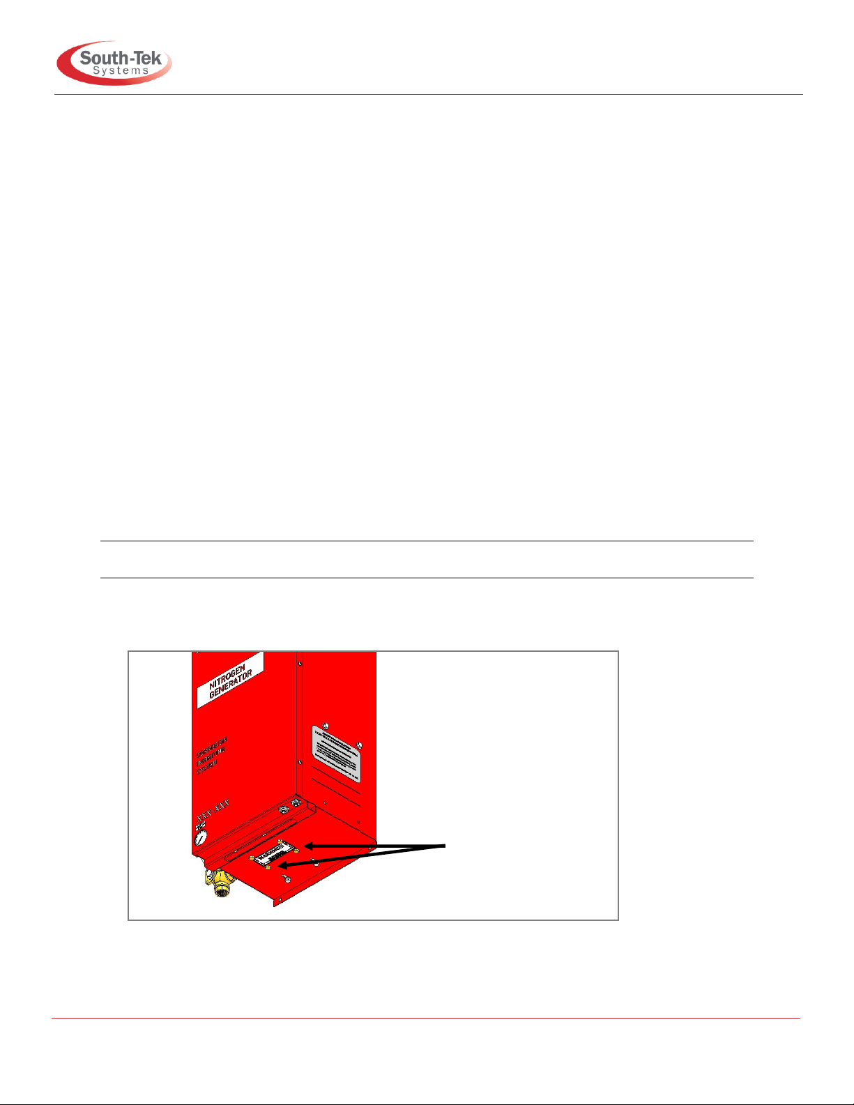
Note: Remove the 4 painted bolts below the cabinet to free up the compressor’s vibration isolators.
Carefully, break down the cardboard box and store in a safe location. Reuse the cardboard box if
returning for factory service.
Figure 1: Remove shipping bolts (x4)
Remove these 4
bolts underneath
the cabinet prior to
starting up the unit

P
The Leader in Nitrogen Generation Technology
FPS-900 O&M Manual
Revision: 2; 7/2020
Page 8 of 29
4. Site and Utility Requirements
4.1. Air Supply
The N2-BLAST
®
FPS-900 includes a built-in air compressor to supply gas to the nitrogen generator. It is
not for performing quick fills. Please install a separate suitable air compressor for other needs.
4.2. Additional Piping and Hosing
Sourcing and installing additional plumbing, supplied by other manufacturers, must meet all of the unit’s
flow, pressure, and temperature requirements. If piping length between any equipment is greater than
50 feet, consult with a piping contractor for proper line size.
4.3. Electrical Requirements
The N2-BLAST
®
FPS-900 requires 120VAC / 50-60hz / 1ph and draws < 8A. 240VAC is also available
though wiring changes apply. It has a built-in 15A over-current protection device and comes with
terminal strip for the electrical connection. It comes with UL 508A ICP certification, and the electrical
schematics are available upon request.
4.4. Site Specifications
Unless designed otherwise, install in a nonhazardous indoor location with temperatures between 40-
100°F (4°- 38°C). For ease of maintenance, troubleshooting, and minimizing pressure drop, install the
equipment in the same area. Leave enough space around the generator and other equipment for
routine maintenance.

P
The Leader in Nitrogen Generation Technology
FPS-900 O&M Manual
Revision: 2; 7/2020
Page 9 of 29
5. Product Installation
5.1. Mounting
Mount the N2-BLAST
®
FPS-900 on a weight-bearing wall that can support the system’s weight as
specified in this manual. Always install the FPS-900 indoors and upright away from accidental damage
by water or moving equipment. Install it in an environment between 40° and 100° F. Leave at least 6” on
the left side of the cabinet for ventilation. 36” of space is recommended for access to the control panel,
tube/pipe connections, and the front cover. There is a 1/4” OD tube drain port on the bottom right of the
cabinet. Plumb this to the nearest site drain.
There is a wall mounting bracket kit (STS Part #: A05-TYP1-RD), that allows you to mount the system
on a standard 16” wall stud width. Otherwise, use the mounting holes on the cabinet for mounting the
FPS-900 securely and level, directly to wall or to existing rack.
Wall Mounting Bracket Kit Procedures:
1. All N2-BLAST
®
FPS-900 mounting holes and wall mounting bracket holes are for 1/4” screws/anchors
(not provided).
2. All brackets must be installed in orientation as shown to work correctly.
3. Install the cabinet-mounting brackets on the N2-BLAST
®
FPS-900 first with the provided bolts/lock nuts.
4. Optional: If wall studs are not 16” center to center, reinforce the mounting area with a 1/2” or thicker
plywood prior to hanging the system. Use best general practices to ensure that the wood and system
will secure the system at its full weight. Remember that it will be vibrating with the compressor running.
5. Locate the 18” wall-mounting bracket without the rectangular cutouts. Install it leveled on the wall at the
desired height. Mount the bracket directly to the wall studs using the 16” center to center holes. See the
figure below and use the appropriate hardware (not included) for the type of wall material (wood, sheet
metal, masonry, etc.). Once securing the 18” wall bracket, hang the fastened 12” bracket on the
cabinet’s top flange (from step 3) to the 18” wall bracket. Reference the figure below to see how to
orient the angles to the back of the cabinet in comparison to the wall.
a) Use the supplied carriage bolts and nuts to attach the 18” lower bracket to the bottom flange,
but do not tighten the nuts yet. After installing the system, position the unit using the rectangular
slots. Once the final location is determined, tighten the nuts.
6. Secure the bottom flange to the wall. Failure to do so could cause damage or bodily injury.
Warning: Secure the N2-BLAST
®
FPS-900 to the wall at the top and bottom flanges. Failure to do
so could cause damage or bodily injury.
P
The Leader in Nitrogen Generation Technology
FPS-900 O&M Manual
Revision: 2; 7/2020
Page 10 of 29
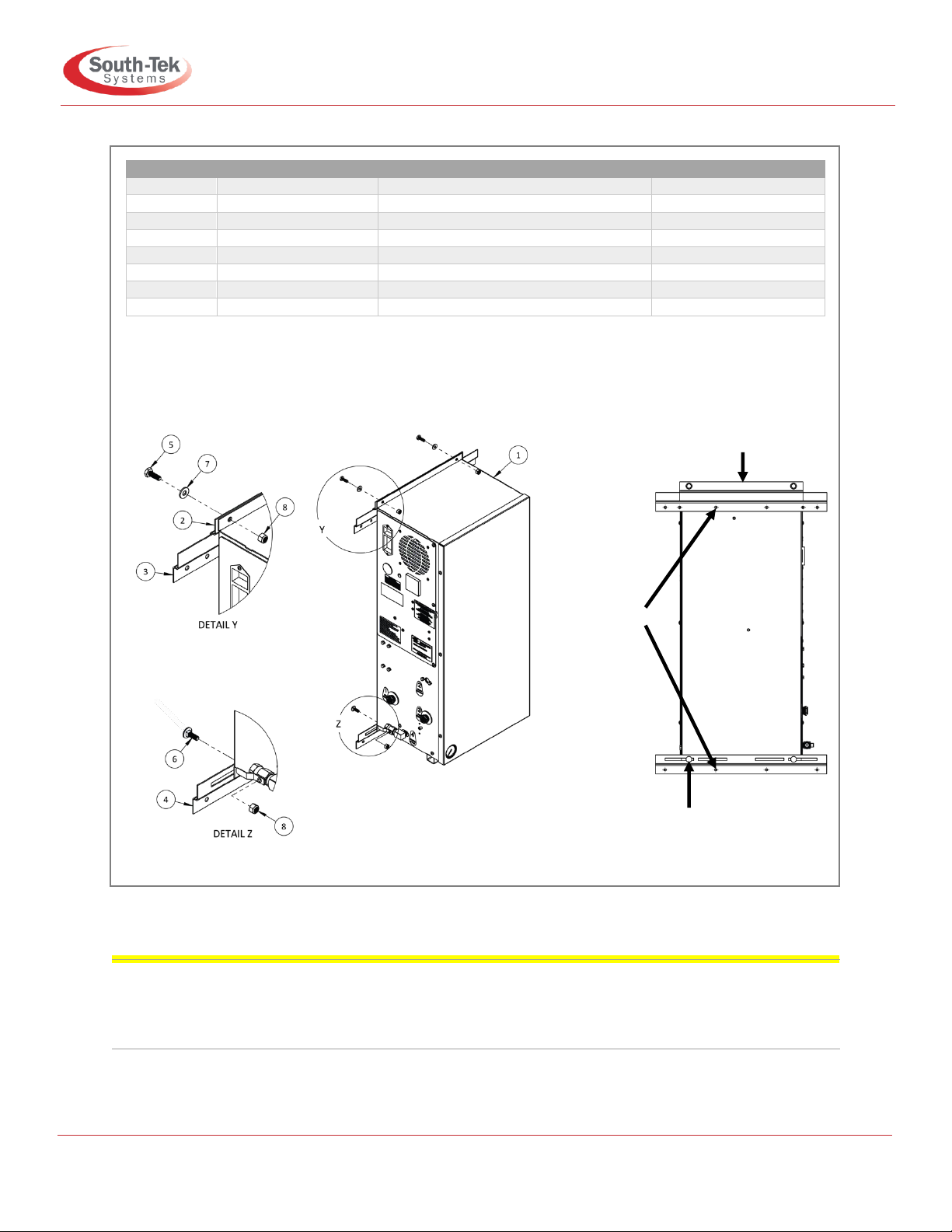
Figure 2: Wall mounting instructions
Note: Install in a location where 6” minimum clearance is available on the sides. Leave 36” minimum on the
front side for maintenance access. Do not install near a heat source or where steam or water is present.
Improper installation may result in bodily harm or damage to the system, as well as voiding the system’s
warranty.
Item #
STS Part #
Description
QTY
1
TYP1P UNIT
TYP1P Unit Shown
1
2
800-133
S-100/200 Mounting Bracket
1
3
800-134-B
TYP1 (18in) Mounting Bracket
1
4
800-129
100/200 Lower Wall Mount Bracket
1
5
002-382
.250” -20 x 0.750” HHCS
2
6
REFERENCE
0.250” -20 x 0.750” Carriage Bolt
2
7
REFERENCE
0.250” Flat Washer
2
8
REFERENCE
0.250” NYLock Nut
4
Fasten bracket securely
to cabinet as in Detail Y
Bracket
should be
secured to
wall studs
with ¼”
hardware
Bracket installed with slotted
edge against cabinet

P
The Leader in Nitrogen Generation Technology
FPS-900 O&M Manual
Revision: 2; 7/2020
Page 11 of 29
5.2 Installation Arrangement
See below for basic setup. Refer to the general arrangement drawing for detail instructions included
with the installation package.
Figure 3: Nitrogen Generator Wall Mount Installation Setup
Note: Nitrogen generator dimensions: 12-3/4” W x 12” D x 27” H (Cabinet dimensions) Nitrogen tank
dimensions: 15” Diameter x 50” H (Recommend 55” for manifold clearance)
Figure 4: FPS nitrogen tank details and connections
Item #
STS Part #
Description
QTY
1
800-111-FPS
100# Red Tank with Label
1
2
A01-0100-A
Tank Strap Assembly
1
3
A01-0100-S-A
Tank Manifold with 0.500” Nozzles
1
Should this handle be
in the closed position,
the generator will be
bypassed by air. This
will light a red indicator
and trigger an alarm if
connected.
Note: Generator is
online and functioning
during this state.
Note: All N2-Blast®
models are factory
equipped with ½” NPT
Female connections.
Air Maintenance device
recommended
Only one line in/out
when using bypass
Nitrogen tank
provided with
brackets and
strap
D-Ring assembly should be
secured to wall using ¼”
hardware (not supplied)
Warp strap around tank and
use plastic clip to secure
tank to wall

P
The Leader in Nitrogen Generation Technology
FPS-900 O&M Manual
Revision: 2; 7/2020
Page 12 of 29
5.3 Panel Layout and Gas Connections
See figures below for panel layout and gas connections. Double-check all connection locations
before turning on the system or opening any valves. Note: All N2-BLAST
®
FPS models are factory
equipped with 1/2" NPT Female connections.
Figure 5: FPS-900 external components and connections
External Components
Item #
Description
Service
1
15 AMP Circuit
Breaker Switch
System Main Power Supply
2
1/2" Trade Size
Conduit Hole
POWER SUPPLY
3
Audible Electrical
Buzzer
Audible Alarm
4
0-100 PSIG
Pressure Gauge
N2-Storage Tank Pressure
Gauge
5
PLC
System Controller
6
¼” OD Through-wall
Coupling
¼” OD Drain
7
½” NPT Way Ball
Valve
AIR BYPASS TOP
8
Red Light
N2 Out Bypass Indicator
9
UL 508A Open Industrial Control Panel Certification
Label
10
Electrical Panel and Terminal Block Torque
Specifications Label
11
Product Serial Number Label
(FRP-007) Filter Replacement Kit
STS Part #
Description
Qty
650-135
Pre-Compressor Filter
1
650-137-MB
Particulate Filter Element
1
650-140-MB
Coalescing Filter Element
1
120-020-E
Replacement O-Rings
2
Design Data
N2 Out Pressure
Up to 70 PSI
Electrical Option 1
110V / 60Hz / 1 Phase, 3.5 AMPs
Electrical Option 2
240V / 50Hz / 1 Phase, 1.4 AMPs
Noise Level (dB)
<60
Weight
84 lbs.

P
The Leader in Nitrogen Generation Technology
FPS-900 O&M Manual
Revision: 2; 7/2020
Page 13 of 29
6. System Design
6.1. Key Features
The N2-BLAST
®
FPS-900 key features include the following:
•Air Compressor
•PLC Controller
•Safety Relief Valves
•N2Tank
•Air Filters
•Pressure Swing Adsorption Beds
•Automatic Pressure Cut-in/Cut-out
•STS Patented BlastOff®
6.1.1.Air Compressor
An oil-less internal air compressor has an engineered dampening system reducing vibration and
noise throughout the cabinet. The air compressor has a pre-filter to catch small particulates that can
cause damage. The recommended replacement for the pre-filter is 1000 run hours or 1-year,
whichever comes first. Dirtier environments may need more frequent changes. Consult with the
supplier for a different filter maintenance schedule if installing in a dirty environment.
6.1.2.Air Filters
The generator has an air inlet pre-filters and two filters between the compressed air and O2
separation beds - the particulate and coalescing. The 5-micron particulate filter catches the bulk
particles, and the 0.1 micron coalescing catches the remaining smaller particles. Both filters feature
an auto-drain that drains any water buildup within the filter housing. These drain lines are on the
cabinet’s bottom right side. Connect these drain lines to a safe location.
6.1.3.PLC Controller
An integrated PLC within the cabinet features smart timing to maximize the generator’s
performance. It controls the valve timing and sequencing to move compressed gas throughout the
system. It also has a smart feature to automatically switch between different “modes” based on the
current run stages (see Chapter 7: System Operation for more about the unit’s functionality).
6.1.4.Safety Relief Valves
The installed ASME safety relief valves add additional safety to protect component failures.
6.1.5.Nitrogen Tank
The nitrogen tank comes with ball valves, safety relief, and a gauge. The outlet gas connects to an
external manual ball valve for easy plug and play connection.

P
The Leader in Nitrogen Generation Technology
FPS-900 O&M Manual
Revision: 2; 7/2020
Page 14 of 29
6.1.6.Automatic Cut-In and Cut-Out
The generator starts and stops based on a pressure switch. Do not adjust the factory preset cut-in
and out pressure without first consulting with South-Tek Systems.
6.1.7.Patented BlastOff®–Leak Detection System
The “BlastOff®Leak Detection” is a patented feature which sends an alarm if it detects a possible
gas leak. The alarm signal can be an audible, visual, and dry contact connection to the “Building
Management System (BMS)”. Power cycle the unit to reset the alarm, but avoid doing this multiple
times, without finding the cause, as it will shorten the generator’s life.
6.2. Specifications
N2-Blast FPS-900
Nitrogen Purity
98.5+%
Installation
Wall Mounted (Optional floor mounting kit available)
Display
Hours / Power On / Operating
N2Storage Pressure
60-70 PSIG
Cabinet Port Connections
½” NPT Female
Electrical
110-220V / 50-60 Hz / 1 Phase; 15 Amp Breaker
Compressor
Integral / Oil-Free
Ambient Temperature
40° to 100°F
Noise Level (dbA)
< 60 dbA
Size
12.75”W x 12”D x 27” H (Cabinet Dimensions)
Weight
84 lbs

P
The Leader in Nitrogen Generation Technology
FPS-900 O&M Manual
Revision: 2; 7/2020
Page 15 of 29
7. System Operation
7.1. General
The nitrogen generator uses valve sequencing to produce nitrogen. The design meets specifications of
a fire protection system. Consult with South-Tek System for written approval before performing any field
changes or customization. Unauthorized changes void all warranties and may cause damages or
malfunctions to the system.
This section describes the major control functions and instrumentations associated with the nitrogen
generators. All programs are proprietary and password protected from the factory. Do not alter any
controls or instrumentations. Changes without South-Tek Systems’ written consent voids the
performance specifications.
Note: This section does not include the controls for supporting equipment, such as an external
compressor or dryer. Consult the original manufacturer’s manual for further information.
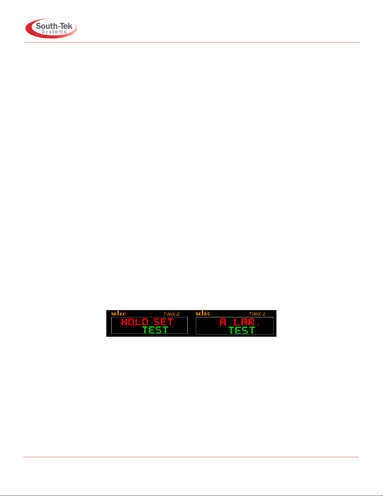
Figure 6: Controller Display
Note: Install the nitrogen generator per “Section 5: Product Installation” and perform the startup procedures
in “Section 8: Startup Procedures” before performing normal operations.
P
The Leader in Nitrogen Generation Technology
FPS-900 O&M Manual
Revision: 2; 7/2020
Page 16 of 29
7.2. Normal Run/Standby Mode
“Running” mode is when the FPS-900 is producing nitrogen and supplies it to the storage tank. The
system will automatically enter “Standby” mode when the tank is fully pressurized (65-75 PSIG). It
will remain in “Standby” mode until the tank pressure falls 7-10 PSIG.
•Controller Modes
This mode allows access to several features:
•Filter Change Reset - Once the nitrogen generator has been running for 1,000 hours or more, the
filter replacement alarm will activate the audible buzzer, alarm contact, and flash “FILTER CHANGE”
on the controller’s 7-segment display. Replace the filters according to Section 9 Maintenance. After
replacing the filter elements, press and hold the Filter Change Reset button (Down Button) for 7
seconds. Screen will show “FILTER RESET” and audible beep will confirm that the time is reset, and
the filter alarm will shut off if it is active. (Note: resetting this will also trigger the Customer Alarm
Relay for one second).
•Blastoff®Simulation - Hold the (Set Button) for 7 seconds Passcode Screen will pop up,
1. Press the (Set Button) one time to activate data entry, Enter (6557) using the (Up and Down
Buttons)
2. Press the (ENT Button) to confirm the entry.
It will bring (HOLD SET) Screen, to simulate the Blastoff, press and hold the Set Button for 5
seconds this will simulate the Blastoff and trip the alarm dry contact in the unit (if installed) for 2
seconds so that proper functioning can be confirmed.
•Next Button - to navigate between the screens as filer hours, program version, unit ambient
temperature, and the sensors screens if it’s applicable (check appendix A).
To run the system in normal run mode:
1. Connect the correct power supply to the system.
2. Open the nitrogen generator’s 3-way outlet ball valve (lower left side of the cabinet) to nitrogen
out position.
3. On the nitrogen tank, open the gas inlet and outlet ball valve.
4. Push the On/Off toggle button on the upper left control panel to the “On” position (up) and the
system will automatically turn on and start filling nitrogen to the storage tank.
P
The Leader in Nitrogen Generation Technology
FPS-900 O&M Manual
Revision: 2; 7/2020
Page 17 of 29
7.3. Stopping the System
To stop the system:
1. Close off the gas outlet valve on the nitrogen storage tank.
2. System will automatically stop once it reaches the cut-out pressure of approximately 65-75
PSIG.
3. In the case of an emergency shut off, push the On/Off toggle button on the upper left control
panel to the “Off” position. The unit will shut down immediately.
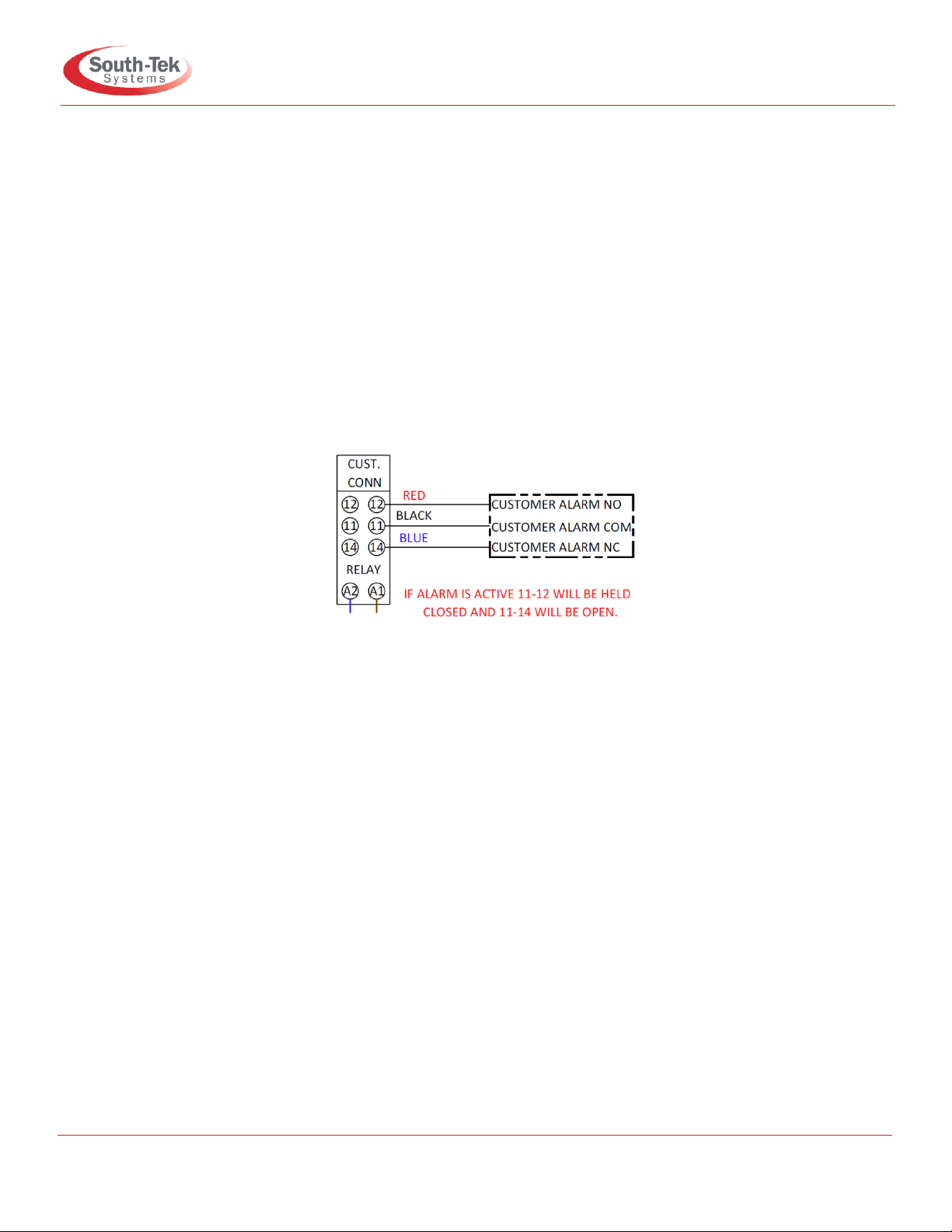
7.4. Power Loss Alarm Mode
The Power Loss Alarm activates when the nitrogen generator loses power for any reason. This will
cause the alarm contact to trigger on the customer common alarm relay.
Figure 7: FPS-900 Alarm Contact Diagram
7.5. Bypass Alarm(Air n2 bypass)
During the 30-minute fire protection piping system fill test, the operator can put the system in manual
bypass mode by turning the handle on the left side of the cabinet. With the handle in the “Bypass
Mode”, the bypass alarm triggers an audible and visual alarm “Air n2 bypass” on the screen. A dry
contact is also available for external notification such as the BMS (Building Monitoring System). The
alarm will turn off once the handle is back to normal run position.
7.6. BlastOff®Alarm(BLAsstoff 9H.run)
The system activates a BlastOff®Alarm when it detects potential leaks or nitrogen being overdrawn.
The “BlastOff®Leak Detection” is a patented feature which sends an alarm if it detects a possible gas
leak. The BlastOff®Alarm will trigger the audible buzzer, alarm contact, and flash “BLAsstoff 9H.Run”
on the controller’s 7-segment display, and dry contact connection to the “Building Management
System’s (BMS)”. Power cycle the unit to reset the alarm, but avoid doing this multiple times without
finding the cause as it will shorten the generator’s life.
Contact South-Tek System or your local installer for further troubleshooting.

P
The Leader in Nitrogen Generation Technology
FPS-900 O&M Manual
Revision: 2; 7/2020
Page 18 of 29
7.7. Communication
(1) (Modbus RTU)
Modbus (RTU) is optional feature our generator offers to our customer to monitor the unit
from BMS (Building Management System).
MODBUS communication can be set up to retrieve real time data. The nitrogen generator
MODBUS Communication settings are as follows:
-Protocol: RTU
-Slave ID: 1
-PLC Controller: Slave
-Bud rate: 119200
-Data Bits: 8
-Parity: none
-Stop Bits: 2
See MODBUS addressing table below:
Function
Data Type
Modbus RTU
Address
Units/Status
Read/
Write
Running / Standby
BOOL
00012
0=Standby, 1=Running
R
Common Alarm
BOOL
00004
1=Good, 0=Alarm
R
BlastOff Alarm
BOOL
00015
0=Good, 1=Alarm
R
Bypass Alarm
BOOL
10005
1=Good, 0=Alarm
R
Filter Alarm
BOOL
00029
0=Good, 1=Alarm
R
Filter Reset Confirm
BOOL
00031
0=Good, 1=Alarm
R
Filter Hours
Register
40019
xxxxx.x / hours
R
(2) Analog output (4-20 OUT)
Another useful and optional feature of (FPS) Reliable System units an analog signal
output (4-20 mA) for current readings of different data points as follow:
(i) Ambient temperature “4-20 out dEGr.F”
(ii) Oxygen content (percent) “4-20 out p.CEnt”
(iii) Oxygen content (ppm) “4-20 out trACE”
(iv) Supply Pressure “4-20 out prEss”

P
The Leader in Nitrogen Generation Technology
FPS-900 O&M Manual
Revision: 2; 7/2020
Page 19 of 29
To setup the analog out:
1) Hold the (Set Button)for 5 seconds Passcode Screen will pop up
2) Press the (Set Button) one time to activate data entry, Enter (6557) using the (Up
and Down buttons)
3) Press the (ENT Button) to confirm the entry.
It will bring (Hold Set) Screen, press (NEXT) button to get to the analog output screen “4-20 out”,
Using the (up and down buttons) buttons to change type of sensor, to confirm press (Set button).
To exits menu press (Next button) to get back to main screen “running or standby”.
Note: For analog output standard units (without advanced options) only will offer ambient temperature
signal, check appendix A.

P
The Leader in Nitrogen Generation Technology
FPS-900 O&M Manual
Revision: 2; 7/2020
Page 20 of 29
8. Start-up Procedures
8.1. Start-up Procedures
Use caution when working with pressurized gas, and install all fittings and gas lines correctly. Always
leak check (see Checking for Leaks section) every line before using the system.
Note: Line leaks will cause the N2-Blast
®
FPS-900 to run excessively, shortening its life and possibly
causing excessive wear on the compressor.
The system documentation package comes with an installation layout drawings. For electronic copies,
please contact your local distributor. Review the complete installation layout drawings. Ensure that you
follow the correct installation drawing per your system’s design. In some cases, a nitrogen bypass
system for pre-filling is required to meet code.
If the system requirements are more complex, please consult the sales representative or equipment
installer for more detailed instructions.
Note: The N2-Blast
®
comes with 1/2” NPT Female inlet and outlet fittings. Use Teflon tape or similar on
all fittings to prevent leakage. When connecting an external air compressor, complete the startup
procedures per manufacturer before starting the nitrogen generator.
The following are standard installation instructions:
1. Complete the installation procedures in section 5.
2. Check the power connection is correct.
3. Turn the 3-way ball valve on the generator’s left side to the “Nitrogen Out” position.
4. Open the inlet ball valve on the nitrogen storage tank.
5. Close the outlet ball valve on the nitrogen storage tank.
6. Push the power button on the left side to the “On” position (up). The air compressor will start up. If
the system is under pressurized or stays in stays in standby until the cut-in pressure is reached. If
neither the operate or standby lights come on, check the wiring and power supply to the generator
unit.
7. Once the system is running, close the tank’s inlet ball valve and monitor the pressure gauge on the
front lower left side of the generator. The pressure gauge will increase to 65-70 PSIG within 2
minutes or less.
a. Once it reaches 65-70 PSIG, the system will enter “Standby” mode and automatically shuts
off the internal air compressor. The PLC will show "standby" on the control panel.
b. Once in standby, note the pressure reading on the front panel. Monitor the pressure for the
next minute for any loss in pressure. If there is a pressure drop, check for leaks around
connection fittings, otherwise proceed to the next step.
8. Open the tank upper ball valve and the system will turn on and fill nitrogen to the storage tank.
9. Completely fill the storage tank and allow the nitrogen generator to go into standby mode.
10. Once in standby mode, monitor the tank pressure gauge for 5 minutes and ensure no leaks are in
the tank. Open the tank upper ball valve after verifying that there are no significant leaks.
Table of contents
Other South-Tek Systems Inverter manuals

South-Tek Systems
South-Tek Systems N2Blast FPS-650 User manual

South-Tek Systems
South-Tek Systems BEERBLAST 7 KPH Operating instructions

South-Tek Systems
South-Tek Systems N2Blast FPS-1750 User manual

South-Tek Systems
South-Tek Systems N2-BLAST FPS-500 User manual

South-Tek Systems
South-Tek Systems N2Blast FPS-15000 User manual


