South-Tek Systems N2Blast FPS-1750 User manual
FPS-1750
FPS-3000
FPS-6000
Fire Protection Systems
O&M Manual
Version 7; 05/24/2016
© 2020
The Leader in Nitrogen Generation Technology

N2-BLAST®Nitrogen Generator FPS-1750, FPS-3000, and FPS-6000 South-Tek Systems
Version: 7
Revision Date: 5/24/16 Page 2 of 25
VERSION HISTORY
Revision
#
Implemented
By
Revision
Date
Approved
By
Approval
Date
Reason
1
J. Nguyen
10/13/13
A. Norman
10/13/13
Initial Release
2
J. Nguyen
7/5/14
A. Norman
7/5/14
3
J. Nguyen
8/15/14
A. Norman
8/15/14
4
J. Nguyen
3/6/15
A. Norman
3/6/15
5
J. Nguyen
10/15/15
A. Norman
10/15/15
Bypass Added
6
J. Nguyen
01/12/16
A. Norman
1/12/16
Updated Information
7
J. Nguyen
5/26/16
A. Norman
5/26/16
FM Approval

N2-BLAST®Nitrogen Generator FPS-1750, FPS-3000, and FPS-6000 South-Tek Systems
Version: 7
Revision Date: 5/24/16 Page 3 of 25
TABLE OF CONTENTS
1INTRODUCTION.................................................................................................................... 6
1.1 Purpose...................................................................................................................... 6
1.2 Audience.................................................................................................................... 6
1.3 Important Information............................................................................................... 6
2SAFETY GUIDELINES.......................................................................................................... 7
2.1 General ...................................................................................................................... 7
2.2 Service....................................................................................................................... 7
3SYSTEM DESCRIPTION ...................................................................................................... 8
3.1 Key Features.............................................................................................................. 8
3.2 Specifications ............................................................................................................ 9
4PRODUCT INSTALLATION.............................................................................................. 10
4.1 Unpacking and Preparation ..................................................................................... 10
4.2 Electrical Requirements .......................................................................................... 10
4.3 Mounting (For N2-BLAST®Nitrogen Generator)................................................... 10
4.4 Installation (For N2-BLAST®Nitrogen Generator) ................................................ 12
4.5 Panel Layout and Gas Connection .......................................................................... 13
4.6 Blastoff™ – Air Bypass setup (Optional)............................................................... 13
4.7 Check for Leaks ...................................................................................................... 13
5SYSTEM USAGE .................................................................................................................. 14
5.1 Instructions.............................................................................................................. 14
5.2 Start-Up Procedures ................................................................................................ 14
5.3 Normal Operating Procedures................................................................................. 14
5.4 Alarm Notification .................................................................................................. 14
6SYSTEM MAINTENANCE.................................................................................................. 16
7KEY CONTACTS.................................................................................................................. 18
8FAQS....................................................................................................................................... 18
8.1 Power Issues............................................................................................................ 18
8.2 Pressure Issues......................................................................................................... 18
8.3 Gas Leaks:............................................................................................................... 19
8.4 BlastOff™ - Leak Detection System: ..................................................................... 19
APPENDIX A: WARRANTY.................................................................................................... 20
APPENDIX B: AUTO PURGE SYSTEM (APS)..................................................................... 21
APPENDIX C: WIRING DIAGRAM....................................................................................... 22

N2-BLAST®Nitrogen Generator FPS-1750, FPS-3000, and FPS-6000 South-Tek Systems
Version: 7
Revision Date: 5/24/16 Page 4 of 25
APPENDIX D: INSTALLATION DIAGRAM........................................................................ 23
APPENDIX E: APS INSTALLATION DIAGRAM................................................................ 24

N2-BLAST®Nitrogen Generator FPS-1750, FPS-3000, and FPS-6000 South-Tek Systems
Version: 7
Revision Date: 5/24/16 Page 5 of 25
--------------------------------------------------Notes---------------------------------------------------

N2-BLAST®Nitrogen Generator FPS-1750, FPS-3000, and FPS-6000 South-Tek Systems
Version: 7
Revision Date: 5/24/16 Page 6 of 25
1INTRODUCTION
1.1 PURPOSE
The N2-BLAST®Nitrogen Generator FPS-1750, FPS-3000, and FPS-6000 (Type II
Series), provide an economical, precise means of generating high purity nitrogen.
Since air is comprised of ~79% N2we simply and cost-effectively separate the N2
from the air. Nitrogen is an inert gas (non-combustible) and widely used in
thousands of industries along with Fire Protection Systems. The N2is “generated”
by means of the air compressor pushing air into the simple, safe membrane
element, which in turn mechanically separates N2molecules from other molecules
found within air.
**The installer and the user should read this manual in its entirety.
1.2 AUDIENCE
This manual is intended for Installer/Supervisory Staff and should be read in its
entirety prior to operation.
Please contact your local distributor provider for any operation and maintenance
first prior to contacting the manufacturer.
1.3 IMPORTANT INFORMATION
All personnel (and their supervisors) installing, operating, and maintaining the N2-
BLAST®Nitrogen Generator must read and fully understand this manual prior to
installing, operating or performing maintenance on the system.
The N2-BLAST®Nitrogen Generator produces nitrogen (N2) at a low flow rate,
which quickly dissipates into the air. N2gas is not poisonous but the gas should not
be directly inhaled since in high concentrations it can cause asphyxiation. Ensure
the unit is installed within a well-ventilated room, one that is not sealed off from
normal living space air changes.
All personnel involved with installation, operations, and maintenance of the N2-
BLAST®Nitrogen Generator must follow safe working practices, OHSA, and local
health/safety code regulations during the installation, operation, and maintenance of
the unit.

N2-BLAST®Nitrogen Generator FPS-1750, FPS-3000, and FPS-6000 South-Tek Systems
Version: 7
Revision Date: 5/24/16 Page 7 of 25
2SAFETY GUIDELINES
2.1 GENERAL
Correct use of N2-BLAST®Nitrogen Generator is important for your personal
safety and for trouble-free functioning of the N2-BLAST®Nitrogen Generator.
Incorrect use can cause damage to the N2-BLAST®Nitrogen Generator or can lead
to incorrect gas supply.
N2-BLAST®Nitrogen Generator produces nitrogen (N2) at a low flow rate, which
quickly dissipates into the air. N2gas is not poisonous but it should not be directly
inhaled, since in high concentrations, they can cause asphyxiation. Ensure that
the unit is installed within a well-ventilated room, one that is not sealed off
from normal living space air changes.
All personnel involved with installation, operations, and maintenance of the N2-
BLAST®Nitrogen Generator must follow safe working practices, OSHA, and local
health/safety code regulations during the installation, operation, and maintenance of
the unit.
Warning:
This manual must be read in its entirety to installing and operating
the N2-BLAST®Nitrogen Generator to prevent accidents and damage
to the N2-BLAST®Nitrogen Generator.
Contact your supplier if you detect a problem that you cannot solve
with this manual.
Only use the N2-BLAST®Nitrogen Generator in accordance with its
designed purpose.
Only service-engineers, that are qualified to work on electric and
pneumatic equipment, are allowed to do the installation, maintenance
and repairs. Unqualified people are not allowed to repair the
equipment.
Do not tamper or experiment with the equipment or exceed the
technical specifications
2.2 SERVICE
Before personnel attempt to service the unit, ensure the power switch has been
turned to the off position, and then disconnect the unit’s external power cord from
the building electrical power supply. Always follow specific manuals from STS
when servicing your system.

N2-BLAST®Nitrogen Generator FPS-1750, FPS-3000, and FPS-6000 South-Tek Systems
Version: 7
Revision Date: 5/24/16 Page 8 of 25
3SYSTEM DESCRIPTION
3.1 KEY FEATURES
The N2-BLAST®Nitrogen Generator key features include the following:
-Air Filters and Pressure Regulator
-Membrane
-Pressure Switch for Automatic Start/Stop (per demand)
-Safety Relief Valve
-N2 Storage Tank
-STS Patented Blast-Off (optional)
Air Filters and Pressure Regulator:
The generator has three filters: the particulate, coalescing, and adsorber filters. The
particulate has a 5 micron filter that will catch any of the larger particles. The
coalescing has a 0.1 micron filter that will catch the remaining smaller particles.
Both filters feature and auto drain that will drain the water captured after the air
compressor. The drain is plumbed to the outside of the cabinet where the end-user
can then connect ¼” tubing and drain to a safe location. The adsorber filter captures
0.003 ppm/wt oil content.
Pressure Switch for Automatic Start/Stop (per demand):
The generator comes with a built in pressure switch to indicate when the nitrogen
demand is needed or has been met. When the pressure switch is triggered (nitrogen
storage tank pressure is met), it will pause the production of nitrogen to the tank.
Once the pressure switch is reset (automatically reset when pressure fall 7-10 PSIG
below set pressure), it will resume the production of nitrogen to the storage tank.
Safety Relief Valves:
Safety Relief Valves have been placed throughout the system for maximum safety.
They are designed and put in place to minimize failure of other components. They
all come with an ASME stamp.
N2 Storage Tank:
A N2 Storage Tank is housed inside the cabinet with manual ball valves and gauge.
It is plumbed to an external manual ball valve so that the end-user will not have to
do any plumbing within the cabinet.
Patented Blast-Off Detection (optional):
The Blast-Off Leak Detection will provide the end-user with an alarm when it
detects characteristics of a leak somewhere on the system. It will trigger an audible
alarm, display it on the screen, and the end-user can tie into the dry contact so that
the alarm can be relayed back to the Building Management System (BMS).
N2-BLAST®Nitrogen Generator FPS-1750, FPS-3000, and FPS-6000 South-Tek Systems
Version: 7
Revision Date: 5/24/16 Page 9 of 25
3.2 SPECIFICATIONS
Table 1: Specification Data
N2-BLAST®Nitrogen Generator FPS-1750, FPS-3000 & FPS-6000 Specifications
Nitrogen Purity
98.0+%
Installation
Wall Mounted
Display
Hours / Operating / Standby / BlastOffTM
N₂Storage Pressure
Up to 80 PSIG
Cabinet Port Connections
1/2" NPT Female
Electrical
110V / 60Hz / 1Phase; 20 Amp Breaker
Compressor
External
Ambient Temperature
40° to 90°F
Noise Level (dbA)
< 80 dbA
Size
42.3’’H x 17’’W x 11.8’’D
Weight
Appx: 85 lbs

N2-BLAST®Nitrogen Generator FPS-1750, FPS-3000, and FPS-6000 South-Tek Systems
Version: 7
Revision Date: 5/24/16 Page 10 of 25
4PRODUCT INSTALLATION
4.1 UNPACKING AND PREPARATION
The N2-BLAST®Nitrogen Generator System’s cardboard carton should be
carefully opened and all parts should be inspected for damage upon receipt.
Identify and verify that all parts listed on the packing list are present and
undamaged. South-Tek Systems (STS) is not responsible for damages that have
occurred during the shipping and handling of the N2-BLAST®Nitrogen Generator.
Any visual damages should be immediately documented and reported to the
shipping company responsible. Then, contact STS at (888)526-6284 to assess the
damages only after the shipping company has been notified.
Until Installation:
oStore the N2-BLAST®Nitrogen Generator in a dry and climate controlled
(60-80°F) room.
oAlways keep the N2-BLAST®Nitrogen Generator in an upright position or
in box as shipped.
oDo not connect the AC power cable until this manual has been read
completely and all connections are made as stated within.
oKeep all gas lines dry so you don’t get moisture in the generator upon
hookup.
oNever place/stack objects on top of the N2-BLAST®Nitrogen Generator.
4.2 ELECTRICAL REQUIREMENTS
The N2-BLAST®Nitrogen Generator requires 110V / 60 Hz / 1ph connection rated
at 20 amp service. It has a built in 20A circuit breaker and a standard 3-prong US
power cord is provided for the electrical connection. The system is UL 508A ICP
approved. Electrical schematic available upon request.
4.3 MOUNTING (FOR N2-BLAST®NITROGEN GENERATOR)
It is recommended that the N2-BLAST®Nitrogen Generator be wall mounted using
its supplied wall mounting brackets. The N2-BLAST®Nitrogen Generator should
always be installed indoors in an environment between 40° and 90° F in the
upright and level position where it will not be damaged by water or moving
equipment.

N2-BLAST®Nitrogen Generator FPS-1750, FPS-3000, and FPS-6000 South-Tek Systems
Version: 7
Revision Date: 5/24/16 Page 11 of 25
Figure 1: N2-Blast® Type II Series Wall Mount Diagram
1. Install the lower mounting bracket on the N2-BLAST®Nitrogen Generator by
sliding the bracket through the keyway on the lower mounting flanges. (Item
#3 into Item #4)
a. Looking at the wall bracket, the hole is installed to the top; the key (a
welded bolt to the bracket) goes to the bottom.
b. Put the supplied ¼” x 1¼” bolt through the holes (2) to lock the bracket
in place. (Insert Item #5 thru Item # 8 and secured with Item # 6)
2. Install the upper mounting bracket on a sturdy wall. The brackets have a 16”
center to center hole set for mounting to a standard studded wall.
a. Use ¼” hardware (min) to support system weight. (Item #2 into Item
#1)
b. Always mount the system away from extreme heat/water/steam
sources. These can cause damage to the system or persons.
3. Once upper mounting bracket is installed, hang the cabinet by sliding the key
through the keyway on the top flange of the N2-BLAST®Nitrogen Generator.
The system should hang level and the lower bracket can now be affixed to the
wall with the same wall mounting hardware. Once the lower bracket is
mounted to the wall, the system is locked into place. To remove the unit from
the wall, simply take the locking bolts out and slide the system off the wall
mounts.

N2-BLAST®Nitrogen Generator FPS-1750, FPS-3000, and FPS-6000 South-Tek Systems
Version: 7
Revision Date: 5/24/16 Page 12 of 25
4. An 110VAC power connection should be installed per local code by a qualified
electrician. See the wiring diagram for specifics. Optionally a standard
110VAC power cord can be installed on the system by a qualified electrician.
Warning: Secure the N2-BLAST®Nitrogen Generator to the wall at the top
and bottom flanges. Failure to do so could cause damage or bodily injury.
4.4 INSTALLATION (FOR N2-BLAST®NITROGEN GENERATOR)
The installation layout drawings are provided with your system in the
documentation package of the system. For electronic copies, please contact your
local distributor. Review and make sure the setup installations are followed per the
installation layout drawings. Ensure that you follow the correction installation
drawing per your system’s design. In some cases, a nitrogen bypass system for pre-
filling is required in the installations to meet NFPA (National Fire Protection
Association) code.
If your system requirements are more complex, please consult your sales
representative or equipment
installer for more detailed installation instructions.
1. The N2-BLAST®Nitrogen Generator is designed with ½” inlet/outlet
connections. Use Teflon tape or similar on fittings to prevent leakage.
2. Install the “Supply Line” coming from the air compressor to the N2-
BLAST®Nitrogen Generator Air Inlet.
3. Connect the N2-BLAST®Nitrogen Generator to the storage tank and then
to the systems Air Maintenance Device(s).
4. Once connections are made and the air compressor has been started
up, slowly open the System’s On/Off Valve.
a. Air will start rushing through the nitrogen generator
b. If there is a leak or bad connection, shut valve off, depressurize the
line, and fix the issue.
c. If a leak within the unit, remove top cover and locate the issue.
Only use factory parts supplied from your distributor or South-
Tek
Systems. Consult the factory for any questions.
5. Once the N2-BLAST®Nitrogen Generatorfills the nitrogen storage tank
to the cut-out pressure (~80 PSIG), the system will enter standby -
green light on the control panel will turn off and orange (standby) light
will turn on. This will stop the air flow through the generator and
eventually stop the air compressor once it reaches the cutout pressure.
a. This will save air and time on the compressor’s motor.
b. This also prolongs life of nitrogen generator’s media and filter life.
i. Lesser quality systems have a constant purge flow
through their systems which decreases system life and
increases the need for maintenance.
6. When you draw nitrogen from the system and the tank pressure falls
below cut-in pressure
(approximately 72 PSIG), the pressure switch will
trigger the system back into run mode and refill nitrogen into the storage
tank automatically. The pressure switch is preset at the factory –no field

N2-BLAST®Nitrogen Generator FPS-1750, FPS-3000, and FPS-6000 South-Tek Systems
Version: 7
Revision Date: 5/24/16 Page 13 of 25
adjustment is required.
4.5 PANEL LAYOUT AND GAS CONNECTION
Air Input is located on the left side of the unit. Nitrogen outlet will be located on
the right side of the unit. Double-check all connection locations before turning on
the system or opening any valves.
Note: All N2-BLAST®models are factory equipped with ½”NPT Female
connections. See drawing (DD-TYP2M-FPS and DD-A01-0100-04-04) for detail
generator and tank connections.
4.6 BLASTOFF™ – AIR BYPASS SETUP (OPTIONAL)
The BlastOff™ - Air Bypass Option ensures that nitrogen is the only supervisory
gas entering the FPS. It safeguards your installation all while providing piece of
mind knowing the FPS is being filled with nitrogen vs any other gas. It will alarm if
the N2-BLAST®Generator is being bypassed by the air compressor. It safeguards
against a maintenance technician from inadvertently leaving the “air bypass” open
or the N2-BLAST®being powered in the off position. It will provide a visual alarm
when it is in alarm mode. See wiring diagram and installation drawing included
with this package. For electronic copies, please contact your local distributor.
4.7 CHECK FOR LEAKS
When a leak is suspected, first try to listen for leaks and/or spray with soapy water
around the connection ports. If a leak is found, isolate the area and relieve any
pressure on it prior to working on it. Fix the leaking part and return the system back
to operation. If no leak are heard (or visually seen with the soapy water), turn off
the unit and try isolating sections to see if there’s a pressure loss. If the BlastOff™
option is included with your unit, the system will alarm indicating that there is a
leak in the line. Consult with your installer if you cannot locate the leakage area.
For more information on leak checking go to Check for Leaks.

N2-BLAST®Nitrogen Generator FPS-1750, FPS-3000, and FPS-6000 South-Tek Systems
Version: 7
Revision Date: 5/24/16 Page 14 of 25
5SYSTEM USAGE
5.1 INSTRUCTIONS
The N2-BLAST® Nitrogen Generator is intended to be used to generate nitrogen
and provide nitrogen for the fire protection piping system. Follow the installation
instructions above and only use in an approved environment. The generator
generates enough nitrogen to maintain zone pressure requirements. Please consult
with your local provider for questions not answered in this manual.
The system is design for 24 hour operation, but routine maintenance on the filters
must be performed. See section “System Maintenance” for detail maintenance
instructions.
5.2 START-UP PROCEDURES
The system is shipped ready for power once the equipment line connections are
completed. Connect the pipe or hose to the nitrogen storage tank outlet using
Teflon tape or other pipe connection sealant. All valves should be open and ready
for gas to be distributed. Plug the N2-BLAST®Nitrogen Generator into a 110VAC
power outlet and turn on the rocker switch. The external air compressor will turn on
if the N2storage tank is not already pressurized. If the nitrogen storage pressure is
at or above the system cut-off pressure, the amber “Standby” light will be
illuminated. Once the pressure drops to the cut-in pressure, the nitrogen generator
will start replenishing the nitrogen into the storage tank. The “Operating” green
light will illuminate until the N2storage tank pressure reaches the cut-out pressure
(approximately 80 PSI) and the external air compressor will cut off once it reaches
its cut-off pressure.
Use caution when working with pressurized gas, making sure that all fittings
and gas
lines are installed correctly. Always leak check (see Check for Leaks
section) every line before using the system.
Note: Line leaks will cause the N2-BLAST®Nitrogen Generator to run
excessively, shortening its life and cause excess wear on the compressor.
5.3 NORMAL OPERATING PROCEDURES
Once the generator has been started-up and the nitrogen storage tank has been
filled, the system should be left power on. The system will automatic start/stop as
the pressure in the nitrogen storage tank reaches the preset cut-in/out pressures. To
pause or bypass the nitrogen open/close corresponding valves as necessary.
5.4 ALARM NOTIFICATION
BlastOff™ - Leak Detection System Alarm
An optional feature that can be included with the system is the BlastOff™ - Leak
Detection System. It is a patented system when installed into the N2-BLAST®
Nitrogen Generator, detects line leaks within the downstream gas lines from the
nitrogen generator to the FPS piping. Line leaks could be due to pin-hole leaks in

N2-BLAST®Nitrogen Generator FPS-1750, FPS-3000, and FPS-6000 South-Tek Systems
Version: 7
Revision Date: 5/24/16 Page 15 of 25
Buzzer and Red Light Warning
This unit is equipped with The BlastOffTM Leak Detection System. If the red
light and buzzer are on,
you may have a leak in one of the gas lines. Note:
To reset alarm, turn power off and close the
nitrogen tank valves. Turn the
power back on. If the unit goes into “Stand-By”mode and shows an orange
light, the generator is operating properly and you have a leak downstream.
Correct the leaks and resume operation. Contact your distributor or the mfg.
as necessary. This is a safety feature
designed to provide a safer operating
environment and to prevent equipment damages or failure
the pipe lines, loose fittings, faulty connection, etc. These leaks are potential safety
hazards, they can cause the nitrogen to deplete quickly, and could cause your N2-
BLAST®Nitrogen Generator to run in excess (decreasing the life of the unit).
Once a leak has been detected, the BlastOff™ will sound the buzzer, and the red
light on the lower left side of the cabinet will illuminate. To reset the BlastOff™,
simply turn off the N2-BLAST®Nitrogen Generator, and turn it back on. The N2-
BLAST®Nitrogen Generator, can be ordered with the BlastOff™ System Factory
installed or the system can be retrofitted in the field. Some rewiring is required to
field install.
Never reset repeatedly; if the BlastOff™ goes off daily, there is a real potential
issue. Consult your installer for a solution. The label below and the Logo above
will be on your FPS if factory installed.
BlastOffTM –Leak Detection System Wiring:
The BlastOffTM can be wired to an external alarm if the customer desires. The
internal relay is set to trigger when there’s an alarm indication. The relay’s dry
contact is configured with 11-14 termination normally open, and 11-12 are
normally closed. BlastOffTM Assembly and customer dry contact relay is located in
the upper left hand portion of the N2-BLAST®Nitrogen Generator’ cabinet’s
interior.
BlastOffTM–Air Bypass Option
The BlastOff™ - Air Bypass Option ensures that nitrogen is the only supervisory
gas entering the FPS. It safeguards your installation all while providing piece of
mind knowing the FPS is being filled with nitrogen vs any other gas. It will alarm if
the N2-BLAST®Generator is being bypassed by the air compressor. It safeguards
against a maintenance technician from inadvertently leaving the “air bypass” open
or the N2-BLAST®being powered in the off position. It will provide a visual alarm
when it is in alarm mode. See wiring diagram in APPENDIX c: Wiring Diagram
and installation instruction in Appendix D: Installation Diagram.
N2-BLAST®Nitrogen Generator FPS-1750, FPS-3000, and FPS-6000 South-Tek Systems
Version: 7
Revision Date: 5/24/16 Page 16 of 25
6SYSTEM MAINTENANCE
Servicing the N2-BLAST®Nitrogen Generator:
Before personnel attempt to service the unit, ensure the power switch has been
turned to the off position, and then disconnect the unit’s external power cord from
the building electrical power supply. Always follow specific manuals from STS
when servicing your system.
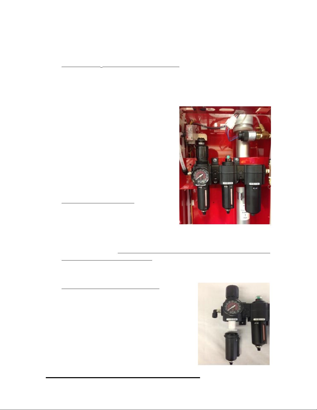
The N2-BLAST®Nitrogen Generator utilize
three different filters, seen in Figure 2 to the
right. The Particulate, Coalescing, and
Absorber filters must be changed out
annually or every 1000 hours (hour meter
located on the outside bottom right corner of
the cabinet) of operating time, whichever
comes first. Filter Replacement Kits can be
purchased from South-Tek Systems that
include the Filter Elements for the specified
unit (STS Part # FRP-002).
Prior to Filter Bowl Removal
Ensure the power has been disconnected
from the source. Air supply to the unit
should also be bypassed, or disconnected
from the unit. You can remove the top cover
to the unit by removing the 4 screws that secure it to the cabinet, however it is not
necessary to do this. The pressure gauge located on the regulator that houses the
Particulate Filter should read 0 psi. If the pressure gauge still shows the system
having pressure, you can relieve the pressure by pulling the safety Relief Valve
ring located after the Absorber Filter.
Particulate Filter Element Replacement
1) Remove Filter Bowl by pressing up slightly
and turning the bowl 1/8 turn to the left,
then pulling down (see Figure 3). After
bowl is removed you will be able to see the
filter element secured in place by a
threaded ring just under the element.
2) Unscrew the thread counter-clockwise, and
the filter element can be removed easily by
pulling down.
3) Install the new Particulate element and
Figure 2: Particulate, Coalescing, and
Absorber, respectively
Figure 3: Particulate Element
Replacement
N2-BLAST®Nitrogen Generator FPS-1750, FPS-3000, and FPS-6000 South-Tek Systems
Version: 7
Revision Date: 5/24/16 Page 17 of 25
secure it in place with the threaded ring.
4) Before reinstallation of the filter bowl, be sure to clean out any debris with
hot water and shake dry the water out.
5) Change the O-ring on the top of the bowl with the new one supplied in the
kit, use some light oil/grease if the O-ring seems to be dry.
6) To reinstall the filter bowl, reverse the procedures used in removing the
filter bowl.
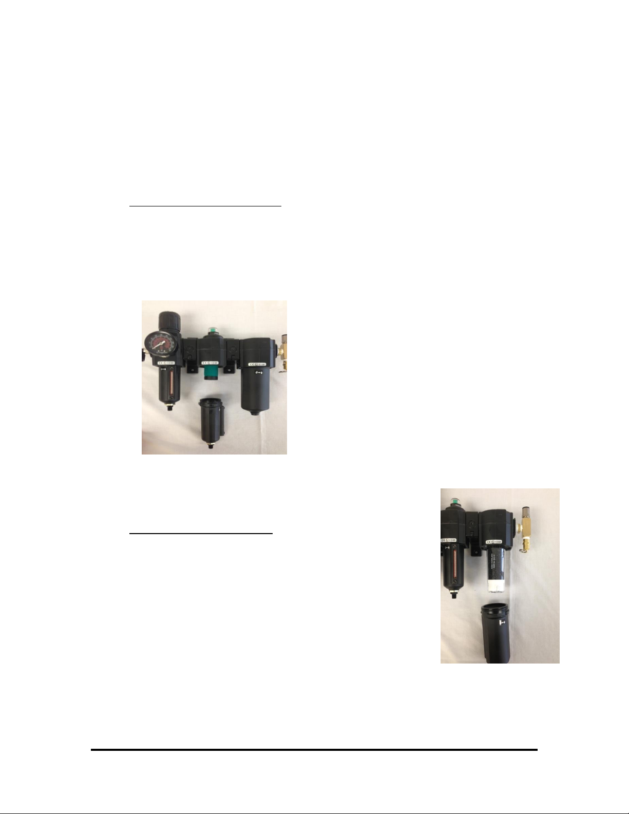
Coalescing Filter Replacement
1) Remove the filter bowl by pushing up slightly and turning the bowl 1/8
turn to the left then pulling down (See Figure 4). After the bowl is
removed, you’ll be able to see the filter element still secured in place.
2) The element can be removed by twisting counter-clockwise until the filter
element comes completely off. 3) Install the new element by
twisting clockwise. HAND TIGHT ONLY!
4) Before reinstallation of the filter
bowl, rinse out the bowl of any debris with hot
water and shake dry the water out.
5) Change the O-ring on the top of
the bowl with the new one supplied in the kit,
use some light oil/grease if the O-ring seems to
be dry. 6) To reinstall the filter bowl,
reverse the procedures used in removing the
bowl.
Absorber Filter Replacement
1) Remove filter bowl by pressing up slightly and
turning the bowl 1/8 turn to the left then pulling
down (See Figure 5). After the bowl is removed,
you’ll be able to see the filter element still secured in
place.
2) The Element can be removed by unscrewing counter-
clockwise.
3) Install the new element with new O-Ring by
screwing clockwise. HAND TIGHT ONLY!
4) Before reinstallation of the filter bowl, be sure to
rinse it out thoroughly with hot water and shake dry.
5) Change the O-ring on the top of the bowl with the new one supplied in the
kit, use some light oil/grease if the O-ring seems to be dry.
Figure 4: Coalescing Filter Element
Replacement
Figure 5:
Absorber Filter

N2-BLAST®Nitrogen Generator FPS-1750, FPS-3000, and FPS-6000 South-Tek Systems
Version: 7
Revision Date: 5/24/16 Page 18 of 25
6) To reinstall the filter bowl, reverse the procedures used in removing the
filter bowl.
Reconnecting Your N2-BLAST®Nitrogen Generator:
1) After all filter elements have been replaced, wipe down all surfaces with a
clean dry towel. Do not use any cleaning agents as they could damage the
finish on the filters.
2) Reconnect to power source and slowly open the incoming air supply ball
valve.
3) After the system has been powered up, listen for any air leaks to ensure
filter bowls have been adequately tightened.
4) If no leaks are present, allow the system to fill up the storage tank.
7KEY CONTACTS
Contact your local provider/installer for any questions with the performance and/or
maintenance of the system. They will be best suited to answer your questions and
your quickest solution on any issues you may have.
8FAQS
8.1 POWER ISSUES
If the N2-BLAST®Nitrogen Generator does not have power, the production and
storage of nitrogen will become apparent once the storage pressure drops.
1. Check the power cord
2. Has building’s circuit breaker or GFCI tripped? Locate the breaker and
reset. If breaker continues to trip, you may have that circuit overloaded.
8.2 PRESSURE ISSUES
The N2-BLAST®Nitrogen Generator will produce and store nitrogen at 70 (+/-3)
psig. Once the storage tank reaches 70 (+/-3) psig, the system will go into Stand-
By Mode. When the pressure drops by about 7-10 psig, the system should go into
Operation Mode and begin to refill the storage. If you are out specifications, we
need to determine where the issue is. Contact the manufacturer or factory trained
technician.
Nitrogen Pressure Check:
Look at the pressure gauge on the top of the cabinet. It should be between 50 and
80 psig. If the pressure is low, a few things need to be checked.
Check the power.
Check leaks throughout system. Refer to section “Checking for Leaks”.

N2-BLAST®Nitrogen Generator FPS-1750, FPS-3000, and FPS-6000 South-Tek Systems
Version: 7
Revision Date: 5/24/16 Page 19 of 25
8.3 GAS LEAKS:
As with any gas system, only use a spray bottle on non-electrical equipment to find
leaks. Fix or replace leaking fittings or old hose. Push-to-connect fittings will show
bubbles and typically have up to a 5ccm acceptable leakage rate. Contact your local
provider/installer for help.
8.4 BLASTOFF™ - LEAK DETECTION SYSTEM:
“There is an alarm sounding in the N2-BLAST®
Nitrogen Generator and the control panel has Blast Off light
illuminated on the side panel of the unit.”
If you hear the alarm and see the red “BlastOff light on, it means that the system is
equipped with “The BlastOff™- Leak Detection” feature. If the BlastOff is
activated, there may be a leak in one of the lines, internal system components, or
fittings may not be properly seated, causing gas leaks. Note: Turn off this unit’s
on/off power switch and check for leaks. If none are found, leave the unit turned
off and contact your local FPS contractor. Once the leak has been fixed, turn the
system back “On” to resume normal operation. By turning the system power off,
then back on, this will reset the BlastOff™ automatically.

N2-BLAST®Nitrogen Generator FPS-1750, FPS-3000, and FPS-6000 South-Tek Systems
Version: 7
Revision Date: 5/24/16 Page 20 of 25
APPENDIX A: WARRANTY
The N2-BLAST®Nitrogen Generator System is warrantied against any defects in
workmanship and materials for 12 months (or 1000 hours) from the date of shipment
from South-Tek Systems, whichever comes first. The purchaser has the liability to ensure
that the system is fully inspected upon delivery and shall contact the appropriate shipping
company to make any claims on damaged goods due to transit within that shipping
company’s policies. If the system is received with defects that are not due to shipping, a
written claim should be submitted to South-Tek Systems within 1 week of receiving the
shipment. South-Tek Systems can deny all other claims at their discretion.
All warranty work shall be done at a South-Tek System facility or at a N2-BLAST®
Nitrogen Generator Authorized Service Center. Only factory trained and authorized
personnel are covered under warranty. Any part that is returned / repaired / replaced
under warranty may be remanufactured or changed to a different specification at the
factory’s option. Any work performed by an unauthorized person/company or usage of
non-factory parts, may void all warranties to the product.
Any item not manufactured by South-Tek may carry its own warranty from its
manufacturer and will be warrantied by that manufacturer. All parts that need to be
returned should be announced. Any item(s) that is returned to South-Tek Systems
without an RMA number (return authorization number) may be denied and returned to
the sender. Contact the factory for RMA #’s, prior to return shipment.
South-Tek Systems is not liable for damages caused by normal wear and tear, water, fire,
erosion, corrosion, explosion, misuse, oil/gas vapors or unauthorized modifications.
South-Tek Systems is also not liable for any losses (including CO2), damages, or cost of
delays, including incidental or consequential damages. There are no warranties or
guarantees, expressed or implied, including the warranties of merchantability or fitness
for a particular purpose or use, other than those warranties expressed herein.
For Claims, contact South-Tek Systems LLC at:
tel (919) 847-3800 fax (919) 847-0255
Email: [email protected]
Or write to:
South-Tek Systems, Warranty Claims, 4724 Sharpstone Lane, Raleigh, NC 27615
This manual suits for next models
2
Table of contents
Other South-Tek Systems Inverter manuals

South-Tek Systems
South-Tek Systems N2Blast FPS-650 User manual

South-Tek Systems
South-Tek Systems N2Blast FPS-900 User manual

South-Tek Systems
South-Tek Systems N2-BLAST FPS-500 User manual

South-Tek Systems
South-Tek Systems N2Blast FPS-15000 User manual

South-Tek Systems
South-Tek Systems BEERBLAST 7 KPH Operating instructions
Popular Inverter manuals by other brands


Zgonc
Zgonc yellow PROFILINE YPL 6000-D Translation of original instruction manual

SMA
SMA SUNNY BOY STORAGE 3.8-US installation manual

Phase Green
Phase Green PhG-P5 K0HT-M Series user manual

Huawei
Huawei SUN2000-33KTL-US user manual

ETQ
ETQ TG1200 owner's manual

SolaX Power
SolaX Power X3-Retro Fit Series Quick installation guide