South-Tek Systems BEERBLAST 7 KPH Operating instructions

Copyrighted All Rights Reserved 2016
BEERBLAST™ 7/14KPH
& N2-GEN™ 7/14KPH
O&M MANUAL
Revision 1
Date 06/13/16
NOTE: SCHEMATICS and BROCHURES APPENDED

BeerBlast™ 7/14KPH & N2-GEN™ 7/14KPH O&M South-Tek Systems
2
VERSION HISTORY
Revision
#
Implemented
By
Revision
Date
Approved
By
Approval
Date
Reason
0
James Nguyen
12/15/14
J. Nguyen
12/15/14
1
James Nguyen
6/13/16
J. Nguyen
6/13/16

BeerBlast™ 7/14KPH & N2-GEN™ 7/14KPH O&M South-Tek Systems
3
--------------------------------------------------------------------------Notes Page------------------------------------------------------------------------

BeerBlast™ 7/14KPH & N2-GEN™ 7/14KPH O&M South-Tek Systems
4
TABLE OF CONTENTS
1INTRODUCTION ............................................................................................................................................................... 6
1.1 Purpose............................................................................................................................................................6
1.2 Audience..........................................................................................................................................................6
1.3 Important Information.......................................................................................................................................6
2SAFETY GUIDELINES......................................................................................................................................................7
2.1 General............................................................................................................................................................7
3SYSTEM DESCRIPTION................................................................................................................................................... 8
3.1 Key Features ...................................................................................................................................................8
3.2 Specifications (BeerBlast™ 7KPH / N2-GEN™ 7KPH) ...................................................................................9
3.3 Specifications (BeerBlast™ 14KPH / N2-GEN™ 14KPH) ...............................................................................9
3.4 System Operations........................................................................................................................................10
4PRODUCT INSTALLATION............................................................................................................................................11
4.1 Unpacking and Preparation (BeerBlast™ 7KPH / N2-GEN™ 7KPH)............................................................11
4.2 Unpacking and Preparation (BeerBlast™ 14KPH / N2-GEN™ 14KPH)........................................................12
4.3 Electrical Requirements.................................................................................................................................13
4.4 Mounting (BeerBlast™ 7KPH / N2-GEN™ 7KPH) .........................................................................................13
4.5 Installation (BeerBlast™ 7KPH / N2-GEN™ 7KPH) ......................................................................................15
4.6 Gas Connection (BeerBlast™ 7KPH / N2-GEN™ 7KPH)..............................................................................18
4.7 Installation (BeerBlast™ 14KPH / N2-GEN™ 14KPH) ..................................................................................20
4.8 Nitrogen Cylinder Back-Up (BeerBlast™ 7/14KPH / N2-GEN™ 7/14KPH)...................................................22
4.9 Start-Up Procedures (BeerBlast™ 7/14KPH / N2-GEN™ 7/14KPH).............................................................22
4.10 Checking for Leaks........................................................................................................................................23
4.11 Access Controls.............................................................................................................................................24
4.12 Starting the System .......................................................................................................................................24
4.13 Stopping the System......................................................................................................................................24
5SYSTEM USAGE ............................................................................................................................................................25
5.1 Instructions ....................................................................................................................................................25
5.2 Alarm Notification...........................................................................................................................................25
6SYSTEM MAINTENANCE............................................................................................................................................... 26
7KEY CONTACTS.............................................................................................................................................................28
8FAQS ...............................................................................................................................................................................28
8.1 Power Issues .................................................................................................................................................28
8.2 Pressure Issues.............................................................................................................................................28
8.3 Gas Leaks......................................................................................................................................................29
8.4 Temperature Issues: Very Common Issue....................................................................................................29
8.5 BlastOff™ - Leak Detection System:.............................................................................................................29
APPENDIX A: WARRANTY.................................................................................................................................................30

BeerBlast™ 7/14KPH & N2-GEN™ 7/14KPH O&M South-Tek Systems
5
----------------------------------------------------------------------------Notes------------------------------------------------------------------------------

BeerBlast™ 7/14KPH & N2-GEN™ 7/14KPH O&M South-Tek Systems
6
1INTRODUCTION
1.1 PURPOSE
The BeerBlast™ 7/14KPH / N2-GEN™ 7/14KPH provide an economical, precise means of supplying mixed beer
gas to “push” the beer to the tap within restaurant and bar establishments. Beer brewers have established
recommended Carbon-Dioxide (CO2) and Nitrogen (N2) mixed gas ratios to protect the kegged product quality,
eliminating over-foaming or under-carbonation, while increasing the keg life. Precise mixed beer gas lowers
operational costs, increases yields/profits, and ultimately provides a higher level of customer satisfaction. This
system can also be used for wine or specialty mixed drink dispensing systems.
South-Tek System’s line of BeerBlast™ 7/14KPH / N2-GEN™ 7/14KPH products consist of an internal a) N2
generator, b) compressor, and c) CO2/N2dual output gas blender (the N2-GEN™ 14KPH does not come with a gas
blender). Since air is comprised of ~79% N2we simply and cost-effectively separate the N2from the air. Nitrogen
is an inert gas (non-combustible), which is even used to package food products for increased shelf life. The N2is
“generated” by our pressure swing adsorption (PSA) technology, where compressed air cycles back and forth
between two beds. As needed, the high purity N2is then forwarded to the integral McDantimTM dual output gas
blender (only in the BeerBlast™ 14KPH and 7KPH model) which precisely blends the N2with the CO2from the
restaurant/bar’s in house storage cylinder/tank. The standard CO2/N2blends available are 60% / 40% and 25% /
75%. The blends are accurate to within 2%. Custom CO2/N2blends are available if desired.
**The installer and the user should read this manual in its entirety.
1.2 AUDIENCE
This manual is intended for Installer/Restaurant/Bar Operator/Supervisory Staff and should be read in its entirety
prior to operation.
Please contact your local Beer Gas provider for any operation and maintenance first prior to contacting the
manufacturer.
1.3 IMPORTANT INFORMATION
Before personnel attempt to service the unit, ensure the power switch has been turned to the off position, and then
disconnect the unit’s external power cord from the building electrical power supply if possible. Always follow
specific manuals from STS when servicing your system.
The BeerBlast™ 7/14KPH / N2-GEN™ 7/14KPH produces a gas blend of Carbon Dioxide (CO2) and Nitrogen (N2)
at a low flow rate, which quickly dissipates into the air. CO2and N2gases are not poisonous but they should not be
directly inhaled, since in high concentrations, they can cause asphyxiation. Ensure that the unit is installed
within a well-ventilated room, one that is not sealed off from normal living space air changes.
All personnel involved with installation, operations, and maintenance of the BeerBlast™ 7/14KPH / N2-GEN™
7/14KPH must follow safe working practices, OSHA, and local health/safety code regulations during the installation,
operation, and maintenance of the unit.

BeerBlast™ 7/14KPH & N2-GEN™ 7/14KPH O&M South-Tek Systems
7
2SAFETY GUIDELINES
2.1 GENERAL
Correct use of the BeerBlast™ 7/14KPH / N2-GEN™ 7/14KPH is important for your personal safety and for trouble-
free functioning of the BeerBlast™ 7/14KPH / N2-GEN™ 7/14KPH. Incorrect use can cause damage to the
BeerBlast™ 7/14KPH / N2-GEN™ 7/14KPH / 7KPH or can lead to incorrect gas supply.
The BeerBlast™ 7/14KPH / N2-GEN™ 7/14KPH produces a gas blend of Carbon Dioxide (CO2) and Nitrogen (N2)
at a low flow rate, which quickly dissipates into the air. CO2and N2gases are not poisonous but they should not be
directly inhaled, since in high concentrations, they can cause asphyxiation. Ensure that the unit is installed
within a well-ventilated room, one that is not sealed off from normal living space air changes.
All personnel involved with installation, operations, and maintenance of the BeerBlast™ 7/14KPH / N2-GEN™
7/14KPH must follow safe working practices, OSHA, and local health/safety code regulations during the installation,
operation, and maintenance of the unit.
Warning:
This manual must be read in its entirety to installing and operating the BeerBlast™ 7/14KPH / N2-GEN™
7/14KPH to prevent accidents and damage to the BeerBlast™ 7/14KPH / N2-GEN™ 7/14KPH.
Contact your supplier if you detect a problem that you cannot solve with this manual.
Only use the BeerBlast™ 7/14KPH / N2-GEN™ 7/14KPH in accordance with its designed purpose.
Only service-engineers, that are qualified to work on electric and pneumatic equipment, are allowed to do
the installation, maintenance and repairs. Unqualified people are not allowed to repair the equipment.
Do not tamper or experiment with the equipment or exceed the technical specifications

BeerBlast™ 7/14KPH & N2-GEN™ 7/14KPH O&M South-Tek Systems
8
3SYSTEM DESCRIPTION
3.1 KEY FEATURES
The BeerBlast™ 7KPH and 14KPH / N2-GEN™ 7KPH and 14KPH key features include the following:
-Air compressor
-Air Filters
-Programmable Logic Controller (PLC)
-Pressure Swing Adsorption Beds
-Safety Relief Valves
-N2Storage Tank
-Automatic Pressure Cut-in/Cut-out
-McDantimTM dual output gas blender (only in BeerBlast™ 7KPH and 14KPH model)
-STS Patented Blast-Off (optional)
Air Compressor:
The air compressor is designed internally to the cabinet and features engineered dampening system to reduce
vibration and noise throughout the cabinet. It is an oil-less compressor with a pre-filter attached to the air input.
The recommended replacement on the pre-filter is 1000 run hours or 1 year (whichever comes first). Dirtier
environments may be required to be changed out more frequently. Consult your supplier for a different filter
maintenance schedule if you are installing the generator in dirty environment.
Air Filters:
The generator has two filters after the air compressor: the particulate and coalescing. The Particulate has a 5
micron filter that will catch any of the larger particles. The Coalescing has a 0.1 micron filter that will catch the
remaining smaller particles. Both filters feature and autodrain that will drain the water captured after the air
compressor. The drain is plumbed to the outside of the cabinet where the end-user can then connect ¼” tubing
and drain to a safe location.
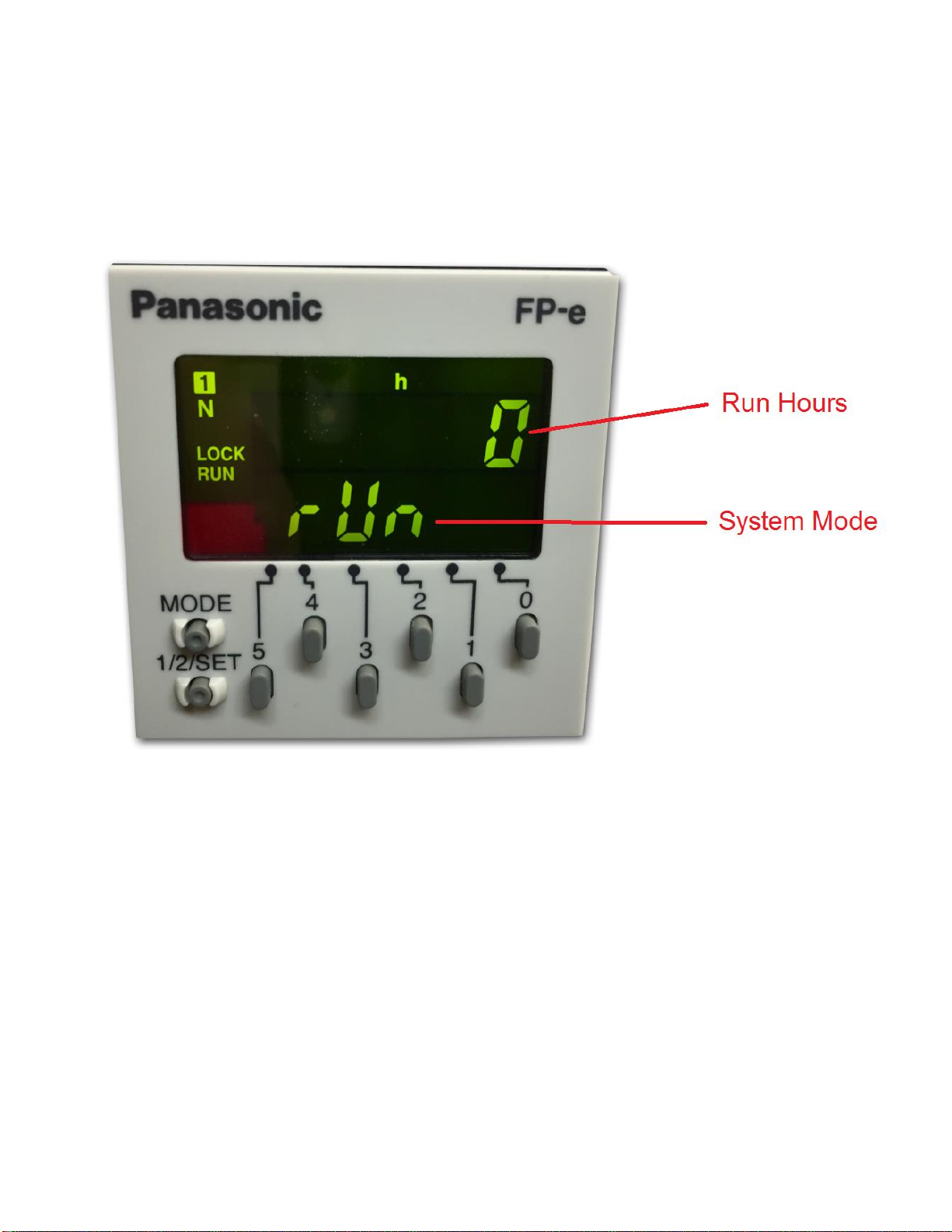
Programmable Logic Controller (PLC):
There’s an integrated PLC within the cabinet. It features smart and efficient coding to maximize the performance
of the generator. It controls the timing and sequencing of the valves to effectively move compressed gas
throughout the system. It also has a smart feature to automatically go into different “modes” based on the
current run stages. It comes with a visual screen that will display run hours and alarms.
Safety Relief Valves:
Safety Relief Valves have been placed throughout the system for maximum safety. They are designed and put
in place to minimize failure of other components. They all come with an ASME stamp.
N2Storage Tank:
A N2Storage Tank is housed inside the cabinet with manual ball valves and gauge. It is plumbed to an external
manual ball valve so that the end-user will not have to do any plumbing within the cabinet.
Automatic Cut-In/Out:
The generator comes with a built in pressure switch that is tied into the PLC. This will provide a low voltage
signal back to the PLC to put the system in a “Standby Mode” when the tank is full of Nitrogen.
McDantimTM dual output gas blender:
Precisely blends N2with CO2from the restaurant/bar’s in house storage cylinder / tank. The standard CO2/N2
blends available are 60% / 40% and 25% / 75%. The blends are accurate to within 2%. Custom CO2/N2blends
are available if desired.
Patented Blast-Off Detection (optional):
The Blast-Off Leak Detection will provide the end-user with an alarm when it detects characteristics of a leak
somewhere on the system. It will trigger an audible alarm, display it on the screen, and the end-user can tie into
the dry contact so that the alarm can be relayed back to the Building Management System (BMS).

BeerBlast™ 7/14KPH & N2-GEN™ 7/14KPH O&M South-Tek Systems
9
3.2 SPECIFICATIONS (BEERBLAST™ 7KPH / N2-GEN™ 7KPH)
BeerBlast™ 7KPH / N2-GEN™ 7KPH –Specifications
Nitrogen Purity
99.8+%
Kegs per hour
7
Installation
Wall Mounted
Display
Hours/Power on/Operating
N₂Storage Pressure
60-70 PSIG
CO₂Gas Requirement
60-80 (min/max) PSIG
Available Blends
60/40 & 25/75 (CO₂/N₂) *Factory Set
Blend Out Pressure
40-50 PSIG min
Cabinet Port Connections
1/4" NPT Female
Electrical
110-220V / 50-60Hz / 1Phase; 20 Amp Breaker
Compressor
Integral / Oil-Free
Ambient Temperature
40° to 85°F
Noise Level (dbA)
< 60 dbA
Size
12.75" W x 12" D x 27" H (Cabinet Dimensions)
Weight
Appx. 100 lbs
3.3 SPECIFICATIONS (BEERBLAST™ 14KPH / N2-GEN™ 14KPH)
BeerBlast™ 14KPH / N2-GEN™ 14KPH –Specifications
Nitrogen Purity
99.8+%
Kegs per hour
14
Installation
Floor standing
Display
Hours / Run / Cool / Standby / Filter Alarm / BlastOffTM
N₂Storage Pressure
60-75 PSIG
CO₂Gas Requirement
60-80 (min/max) PSIG
Available Blends
60/40 & 25/75 (CO₂/N₂) *Factory Set
Blend Out Pressure
40-50 PSIG min
Cabinet Port Connections
1/4" NPT Female
Electrical
110-220V / 50-60Hz / 1Phase; 20 Amp Breaker
Compressor
Integral / Oil-Free
Ambient Temperature
40° to 90°F
Noise Level (dbA)
< 80 dbA
Size
26" W x 18" D x 59" H (Cabinet Dimensions)
Weight
Appx 265 lbs
BeerBlast™ 7/14KPH & N2-GEN™ 7/14KPH O&M South-Tek Systems
10
3.4 SYSTEM OPERATIONS
The system has three standard run modes –Run, Cool, and Standby. When the power switch is turned on, the
controller will automatically determine which mode to enter and will display the current run mode on the screen –
“Run” in Green, “Cool” in Yellow, and “StdBy” in Yellow.
“Run” mode is when the BeerBlast™ 14KPH / N2-GEN™ 14KPH is producing nitrogen and feed it to the storage
tank. It will run through a couple cycles and then enter into a “Cool” mode for one cycle. This prevents the internal
air compressor from overheating and over working. The system will automatically enter “Standby” mode when the
tank is fully pressurized (65-75 psig). It will remain in “Standby” mode until the tank pressure falls 7-10 psig.

BeerBlast™ 7/14KPH & N2-GEN™ 7/14KPH O&M South-Tek Systems
11
4PRODUCT INSTALLATION
4.1 UNPACKING AND PREPARATION (BEERBLAST™ 7KPH / N2-GEN™ 7KPH)
The BeerBlast™ 7KPH / N2-GEN™ 7KPH’s cardboard carton should be carefully opened and all parts should be
inspected for damage upon receipt. Identify and verify that all parts listed
on the packing list are present and
undamaged. South-Tek Systems (STS) is not responsible for damages that have occurred during the shipping and
handling of the BeerBlast™ 7KPH / N2-GEN™ 7KPH. Any visual damages should be
immediately documented
and reported to the shipping company responsible. Then, contact STS at
(888)526-6284 to assess the
damages only after the shipping company has been notified.
Until Installation:
Store the BeerBlast™ 7KPH / N2-GEN™ 7KPH in a dry and climate controlled (60-80°F) room.
Always keep BeerBlast™ 7KPH / N2-GEN™ 7KPH in an upright position / or in box as shipped.
Do not connect the AC power cable until this manual has been read completely and all
connections are made as stated within.
Keep all gas lines dry so moisture does not enter generator upon hookup.
Never place/stack objects on top of the BeerBlast™ 7KPH / N2-GEN™ 7KPH.
BeerBlast™ 7/14KPH & N2-GEN™ 7/14KPH O&M South-Tek Systems
12
4.2 UNPACKING AND PREPARATION (BEERBLAST™ 14KPH / N2-GEN™ 14KPH)
The BeerBlast™ 14KPH / N2-GEN™ 14KPH will arrive in a wooden crate. Open the side noted, “Open this side”.
Once the crate is opened, inspect all parts for any damage upon receipt. Take any pictures upon arrival of the
crate, of damages done during shipping. Identify and verify that all parts listed on the packing list are present and
undamaged. South-Tek Systems (STS) is not responsible for damages that have occurred during the shipping and
handling of the BeerBlast™ 14KPH / N2-GEN™ 14KPH. Any visual damages should be immediately documented
and reported to the shipping company responsible. Then, contact STS at (888)526-6284 to assess the damages
only after the shipping company has been notified.
Until Installation:
The BeerBlast™ 14KPH / N2-GEN™ 14KPH can be stored inside the wooden crate until installation. For
extended storage of over a month, open and insert desiccant bags as needed to prevent moisture buildup.
Store the BeerBlast™ 14KPH / N2-GEN™ 14KPH in a dry and climate controlled (60-80°F) room.
Always keep the BeerBlast™ 14KPH / N2-GEN™ 14KPH in an upright position.
Do not connect the AC power cable until this manual has been read completely and all connections are made
as stated within.
Keep all gas lines dry so you don’t get moisture in the generator upon hookup.
Never place/stack objects on top of the BeerBlast™ 14KPH / N2-GEN™ 14KPH.
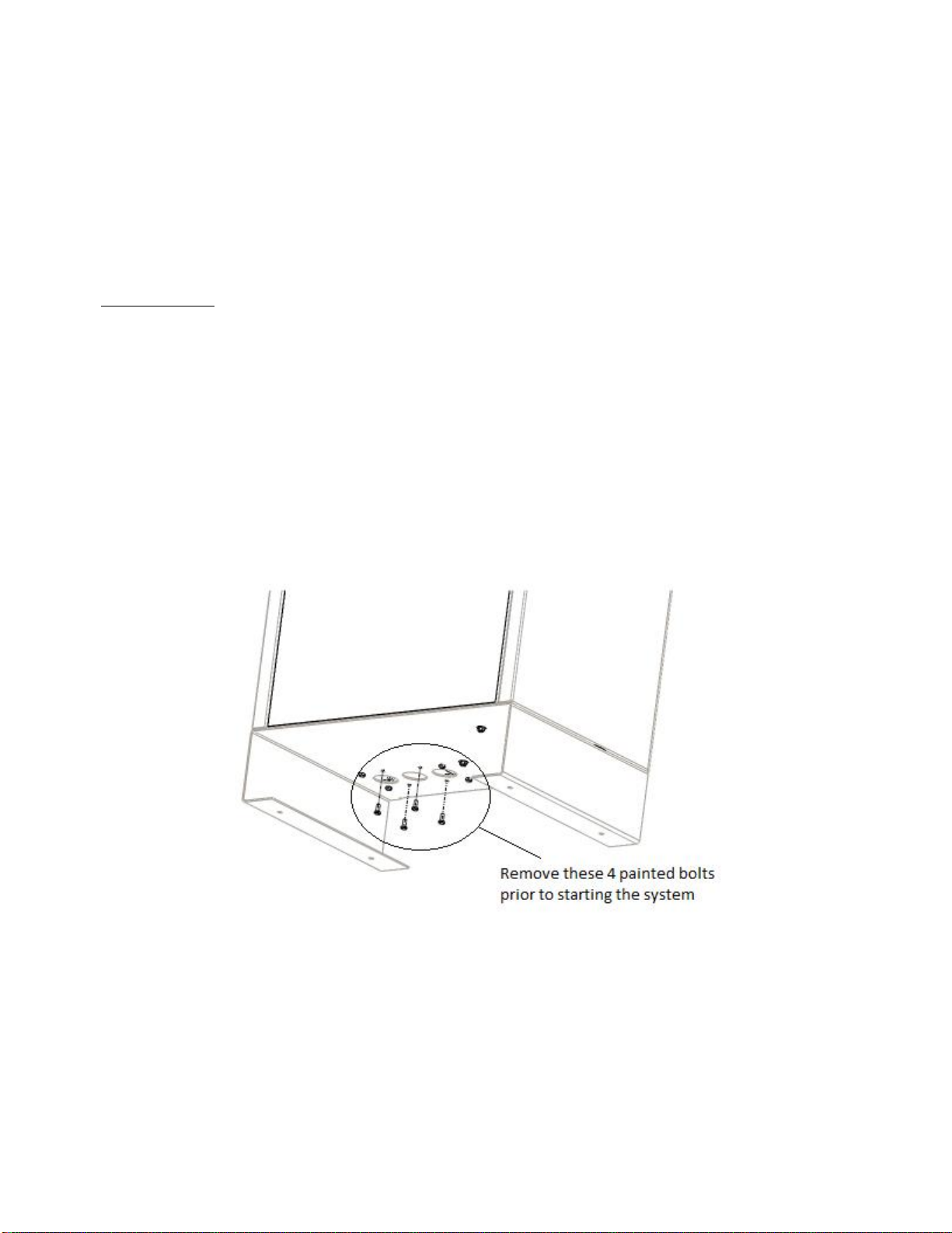
To remove the BeerBlast™ 14KPH / N2-GEN™ 14KPH from the crate, unbolt the cabinet base from the crate.
Carefully, lift the unit from the crate and set it on the floor. The use of a floor jack is advisable to move it to the final
location. Once in place, unbolt the 4 colored bolts at the bottom of the cabinet.
Carefully, break down the crate and store in a safe location in the case that it may need to be sent back to the
factory for service.

BeerBlast™ 7/14KPH & N2-GEN™ 7/14KPH O&M South-Tek Systems
13
4.3 ELECTRICAL REQUIREMENTS
The BeerBlast™ 7/14KPH / N2-GEN™ 7/14KPH requires 110–220V / 50-60 hz / 1ph connection. It has a built in
20A circuit breaker and a standard 3-prong US power cord is provided for the electrical connection. The system is
UL 508A ICP approved. Electrical schematic available upon request.
4.4 MOUNTING (BEERBLAST™ 7KPH / N2-GEN™ 7KPH)
The BeerBlast™ 7KPH / N2-GEN™ 7KPH can be mounted to a wall or placed on a floor. It is recommended that
the BeerBlast™ 7KPH / N2-GEN™ 7KPH be mounted to a weight-bearing wall that can support its weight as
specified in Specifications (BeerBlast™ 7KPH / N2-GEN™ 7KPH). If placed on the floor, it should still be
fastened in place so that it cannot move due to vibration or damaged from falling over. The BeerBlast™
7KPH / N2-GEN™ 7KPH should always be installed indoors in an environment between 40° and 85° F in the
upright position where it will not be damaged by water or
moving equipment. Leave at least 6” on the left side of
the cabinet for ventilation, but 36” is recommended for access to the control panel, tube/pipe connections, and the
front cover. There is a ¼” OD tube drain port on the bottom right of the cabinet. This can be plumbed to the nearest
site drain.
There is an optional mounting bracket kit (STS Part #: A05-TYP1-RD), that allows you to mount the system on a
standard 16” wall stud width. Otherwise, use the mounting holes on the cabinet for mounting the BeerBlast™
7KPH / N2-GEN™ 7KPH securely and level, directly to the wall.
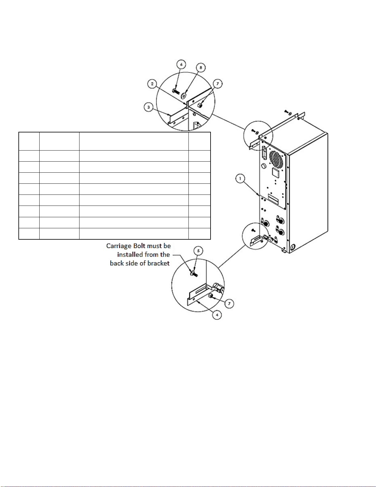
Optional Mounting Bracket Kit Procedures
1. All BeerBlast™ 7KPH / N2-GEN™ 7KPH mounting holes and optional mounting bracket holes are for
¼” screws/anchors.
2. All brackets must be installed in orientation as shown to work correctly.
3. Install the cabinet-mounting brackets on the BeerBlast™ 7KPH / N2-GEN™ 7KPH first with the
bolts/lock nuts that are provided.
4. Locate the wall-mounting bracket. It is an 18” bracket without the rectangular cutouts and will need to
be installed on the wall at the desired height and level. The bracket has 16” center to center holes so
the unit can be mounted directly to studs. This bracket will need to be mounted per the diagram below
using appropriate for your type of wall material (wood, sheet metal, masonry, etc.…). Once the 18”
bracket has been wall mounted, this will allow the 12” bracket that is fastened to the top flange of the
cabinet a fixed anchor to hang from. See diagram as to how the angles are to be oriented on the back
of the cabinet vs the wall.
a. Use the supplied nuts and bolts to attach the upper 12” bracket onto the top flange per the
diagram.
b. Use the supplied carriage bolts and nuts to attach the 18” lower bracket to the bottom flange,
don’t overtighten the nuts yet. After installing the system, you may want to offset the bracket
slightly, hence the rectangular slots.
5. Optional: if wall studs are not 16” center to center or you have the need to reinforce mounting area, a
½” or thicker plywood is recommended to be installed prior to hanging the system. Use best general
practices to ensure that the wood and system will be secure at its full weight and remember that it will
be vibrating from compressor running.
6. Once the mounting brackets are all in place, hang the BeerBlast™ 7KPH / N2-GEN™ 7KPH cabinet
from the top bracket making sure it is centered.
a. The cabinet should have at least 4” on either side for breathing/cooling purposes.
b. Do not install near heat source or where steam or water is present. Damage to system or
bodily harm may result as well as voiding warranty.
Warning: Secure the BeerBlast™ 7KPH / N2-GEN™ 7KPH to the wall at the top and bottom flanges. Failure to do
so could cause damage or bodily injury.
BeerBlast™ 7/14KPH & N2-GEN™ 7/14KPH O&M South-Tek Systems
14
Item
#
STS Part #
Description
Qty
1
BB™ 7KPH
Mini PSA
1
2
800-133
S-100/200 12" Mounting Bracket
1
3
800-134-B
S-100/200/400 18" Mounting Bracket
1
4
800-129
Type 1 Lower Wall Mount Bracket
1
5
Misc
0.250" -20 x 0.750" Carriage Bolt
2
6
Misc
0.250" -20 x 0.750" Hex Cap Screw
2
7
Misc
0.250" Nylock Nut
4
8
Misc
0.250" Flat Washer
2
BeerBlast™ 7/14KPH & N2-GEN™ 7/14KPH O&M South-Tek Systems
15
4.5 INSTALLATION (BEERBLAST™ 7KPH / N2-GEN™ 7KPH)
The BeerBlast™ 7KPH / N2-GEN™ 7KPH Mixed Gas Dispense System can be installed for one or multiple CO2/ N2
blends. It is necessary to use caution when working with pressurized gas, making sure that all fittings and gas lines
are installed correctly. Always leak check every line before using the system.
Note: Line leaks will cause the BeerBlast™ 7KPH / N2-GEN™ 7KPH to run excessively, shortening its life.
In most systems, the BeerBlast™ 7KPH / N2-GEN™ 7KPH can supply two gas blends (of N2and CO2) or a single
Nitrogen output for N2-GEN™ models. These lines can be split individually to provide the correct gas and/or
blended gas to all of the beverage lines. Use only quality beverage tubing and fittings for all connections. Keep in
mind the temperature and pressure requirements when selecting them.
Always install a valve (on/off) on each individual line. This will help with troubleshooting the system. Never detach
a line with pressure on it before closing the valve; this could cause damage to the equipment or bodily injury. Also
avoid depressurizing the keg at all costs; this will negatively affect the beer quality. Always shut off the valve and
remove the tap from the keg before changing or servicing the gas lines.
Two condensate drains for the generator are located on the bottom right of the cabinet. It is the responsibility of the
installer to plumb these drains to an area where standing water is trapped or a drain is located. Failure to do so can
cause a slipping hazard on the floor below the generator.
If your system requirements are more involved, please consult your sales representative or equipment installer for a
customized installation drawing.

BeerBlast™ 7/14KPH & N2-GEN™ 7/14KPH O&M South-Tek Systems
16

BeerBlast™ 7/14KPH & N2-GEN™ 7/14KPH O&M South-Tek Systems
17

BeerBlast™ 7/14KPH & N2-GEN™ 7/14KPH O&M South-Tek Systems
18
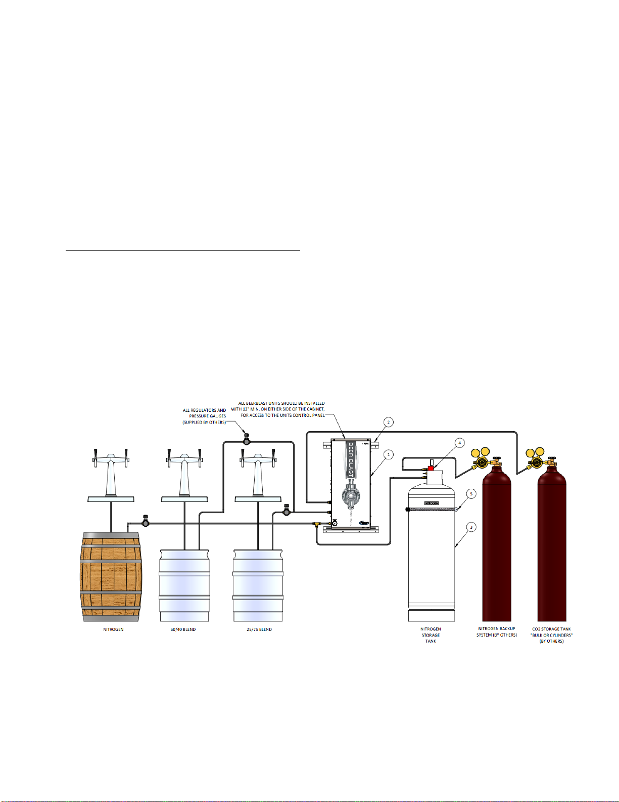
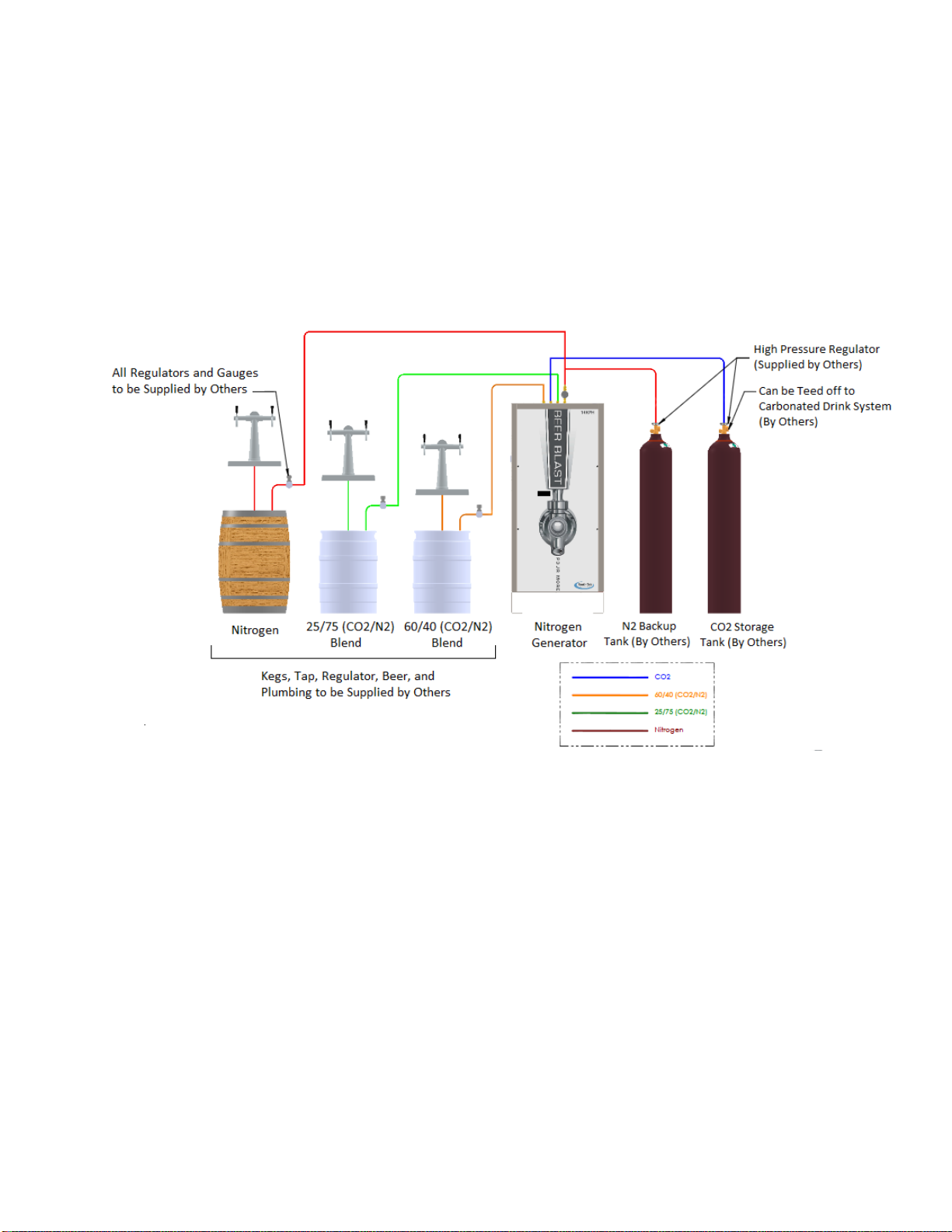
4.6 GAS CONNECTION (BEERBLAST™ 7KPH / N2-GEN™ 7KPH)
See figures below for panel layout and gas connections. Double-check all connection locations before
turning on
the system or opening any valves. Note: All BeerBlast™ 7KPH N2-GEN™ 7KPH models are factory equipped with
½” NPT Female connections.

BeerBlast™ 7/14KPH & N2-GEN™ 7/14KPH O&M South-Tek Systems
19
Figure 1: 100# N2 Storage Tank Setup
BeerBlast™ 7/14KPH & N2-GEN™ 7/14KPH O&M South-Tek Systems
20
4.7 INSTALLATION (BEERBLAST™ 14KPH / N2-GEN™ 14KPH)
The BeerBlast™ 14KPH / N2-GEN™ 14KPH needs to be installed on a hard flat surface capable of supporting 300+
lbs. There are (4) anchor bolt holes on the support legs that can be used to secure the unit to the floor. It is not
required to be anchored, but always follow any site/local codes regarding securing equipment. The unit’s back side
and right side can be pushed all the way against the wall. Leave at least 6” on the left side of the cabinet for
ventilation, but 36” is recommended for access to the control panel (otherwise, the unit will need to be pulled out to
read the display. There are also two ¼” OD drain ports are on the left side of the cabinet. These can be plumbed to
the nearest site drain. The front side of the cabinet requires 36” minimum to gain access to the front door and
perform routine maintenance. Leave enough clearance room on the top of the cabinet for gas line connections. The
N2-GEN™ 14KPH will have the first 3 ports plugged as there is not an internal blender.
Ports on the upper cabinet are as follows (from left to right): Port 1: 60/40 CO2/N2Blend, Port 2: CO2In, Port 3:
25/75 CO2/N2Blend, Port 4, N2Out.
First-time use will require an initial pressurization of the internal storage tank. To perform this task, make sure that
all gas connections are properly made to the kegs. All gas connection ports are ¼” NPT female.
This manual suits for next models
3
Table of contents
Other South-Tek Systems Inverter manuals

South-Tek Systems
South-Tek Systems N2Blast FPS-15000 User manual

South-Tek Systems
South-Tek Systems N2Blast FPS-650 User manual

South-Tek Systems
South-Tek Systems N2Blast FPS-1750 User manual

South-Tek Systems
South-Tek Systems N2Blast FPS-900 User manual

South-Tek Systems
South-Tek Systems N2-BLAST FPS-500 User manual
Popular Inverter manuals by other brands

Airdach
Airdach AIDH2400VG1-D Technical manual

Zgonc
Zgonc yellow PROFILINE YPL 6000-D Translation of original instruction manual

Hoymiles
Hoymiles MI-600T user manual

Hitecsa
Hitecsa ACVIBA HE Series Installation, operation & maintenance manual

Cook's Companion
Cook's Companion Hydro Bottle manual

Raptor
Raptor RAP 225 instruction manual


