Southco J-EA-B90-M User manual
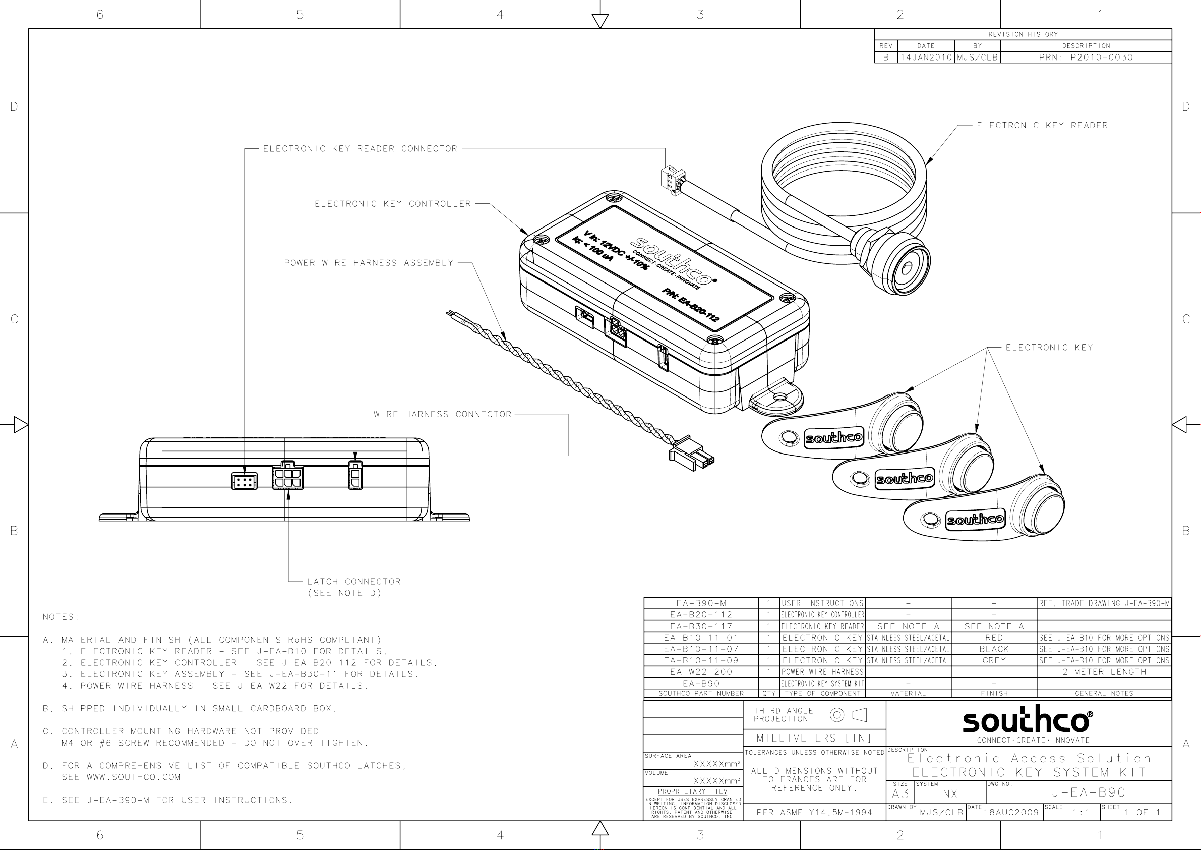

Electronic Key Controller
User Instructions
J-EA-B90-M_revD visit www.southco.com for latest version of this document Page 1 of 2
Specifications
Supply Voltage: 12VDC ± 10%
Quiescent Current: 100µA (max)
Operating Current: 35mA (max)
Command Output Signal Rating: 2A @ 12V (max)
Number of Users: 15 (max)
Access Time: programmable 5- 30 seconds
(default 5 seconds)
CAUTION: The electronic key controller PCA is an ESD-sensitive
device. Observe ESD best practices when accessing the PCA to avoid
damage to the PCA.
Electronic Key Controller
power supply input
controller output to EML
reader input power supply input
controller output to EML
reader input
NOTE: This controller is designed to work with Southco electronic key
reader part number (EA-B30-xxx).
Assembly and Installation
The electronic key controller is part of a system that requires connection to
a power supply, electronic key reader, and electromechanical latch (EML)
to function properly.
Power Supply
The controller requires a 12VDC power supply. Be sure to observe correct
polarity. GND (pin 2)
VCC (pin 1)
GND (pin 2)
VCC (pin 1)
pin #
description
1 VCC (power supply input)
2 GND (ground)
Controller Output to EML
The controller output connector provides a power supply and command
output for an electromechanical latch. Please note that these will be the
same voltage level as the controller’s power supply voltage (12VDC).
command output
(pin 3) VCC
(pin 2) GND
(pin 1)
command output
(pin 3) VCC
(pin 2) GND
(pin 1)
pin #
description
1 GND (ground)
2 VCC (power supply)
3 command output
4 no-connect
5 no-connect
6 no-connect
Electronic Key Reader Input
The electronic key reader reads the ID code from the electronic key and
sends it to the controller. The ID code is unique for each electronic key.
green LED control
(pin 1) data signal
(pin 5)
red LED control
(pin 3)
GND
(pin 6)
GND
(pin 2)
green LED control
(pin 1) data signal
(pin 5)
red LED control
(pin 3)
GND
(pin 6)
GND
(pin 2)
pin #
description
1 green LED control
2 GND (ground)
3 red LED control
4 no-connect
5 data signal
6 GND (ground)
Types of Keys
There are two types of electronic keys for this controller:
1. Programming Key. There is one programming key. This key is
used to add and delete users. The programming key cannot be
used as a user key.
2. User Key. The controller allows for a maximum of 15 user keys
to be enrolled. When an enrolled user key makes proper contact
with the reader, the reader will turn green and access will be
granted for the programmed access time. Note that to make
proper contact, the key must be centered and flat against the
reader.
Reader LED Color Codes
Programming Mode
color
description
solid amber waiting for input
eight green flashes user key enrolled
eight red flashes user key deleted
alternating red/green user key capacity full
one red flash bad key read
User Mode
color
description
solid green access granted (enrolled key)
alternating red/green access denied (un-enrolled key)
three red flashes bad key read

Electronic Key Controller
User Instructions
J-EA-B90-M_revD visit www.southco.com for latest version of this document Page 2 of 2
Enrolling Programming Key (initial setup)
The controller allows for one programming key to be enrolled. By default,
the controller is shipped with no programming or user keys enrolled. The
first key to be enrolled will become the programming key. To enroll the
programming key:
1. Apply power. The reader will flash red/green.
2. Contact the key to the reader. The reader will turn solid amber if
enrollment is successful.
Once the programming key has been enrolled, the controller will enter its
programming mode, indicated by the reader turning amber.
Enrolling User Keys
1. Contact the programming key to the reader (skip this step if this
is during initial setup).
a. The reader will turn solid amber to indicate programming
mode has been entered.
b. If the key made poor contact with the reader, the reader will
flash red three times to indicate a bad read.
2. Contact the user key to the reader.
a. The reader will flash green eight times if enrollment is
successful.
b. If the key made poor contact with the reader, the reader will
flash red once to indicate a bad read.
3. To enroll additional user keys, wait for the reader to turn solid
amber, and then repeat Step #2.
Note: The controller supports a maximum of 15 user keys. The
reader will flash red/green if more than 15 keys are attempted to
be enrolled.
4. Contact the programming key to the reader when done. The
reader will turn “off” indicating that enrollment is complete. The
controller will exit programming mode.
Deleting User Keys
1. Contact the programming key to the reader.
a. The reader will turn solid amber to indicate programming
mode has been entered.
b. If the key made poor contact with the reader, the reader will
flash red three times to indicate a bad read.
2. Contact the user key to the reader.
a. The reader will flash red eight times to indicate that removal
was successful.
b. If the key made poor contact with the reader, the reader will
flash red once to indicate a bad read.
3. To delete additional user keys, wait for the reader to turn solid
amber, and then repeat Step #2.
4. Contact the programming key to the reader when done. The
reader will turn “off” indicating that removal is complete. The
controller will exit programming mode.
Changing Access Time
The default access time is 5 seconds. The access time can be increased
in 5 second increments to a maximum of 30 seconds by pressing the S1
switch on the PCA inside the controller box while the controller is in
programming mode.
1. Contact the programming key to the reader.
a. The reader will turn solid amber to indicate programming
mode has been entered.
b. If the key made poor contact with the reader, the reader will
flash red three times to indicate a bad read.
2. Press the S1 switch on the PCB inside the controller box to add
5 seconds to the access time. The reader will blink once.
3. Repeat Step #2 to increase access time in 5 second increments.
Note: The maximum access time is 30 seconds. The reader will
alternate flashing red/green and the access time will be set to 5
seconds if the 30 second maximum is exceeded.
4. Contact the programming key to the reader when done. The
reader will turn “off” indicating that the access time has been set.
The controller will exit programming mode.
S1 switchS1 switch
Resetting the Controller
Resetting the controller will erase the programming and all user key
permissions. Access time will be reset to 5 seconds. To reset the
controller:
1. Remove power.
2. Press and hold the S1 switch on the PCB inside the controller
box while re-applying power. The reader will be amber at power-
on while the S1 switch is pressed in.
3. Release the S1 switch. The reader will alternate red/green.
Follow the instructions from “Enrolling Programming Key (initial setup)”
section to enroll the programming key.
Normal Use
For normal use, contact a user key to the reader.
If an enrolled user key makes proper contact with the reader, the reader
will turn solid green and access will be granted for the programmed access
time.
If an un-enrolled key makes contact with the reader, the reader will
alternate flashing red/green for approximately 3 seconds.
If a key does not make proper contact with the reader, the reader will flash
red three times to indicate a bad read.
CAUTION: A controller that has been programmed is non-returnable.
Please use caution in programming functions so as not to render the
controller unusable.
For technical support of this product contact: info@southco.com
or visit: www.southco.com.
Other Southco Door Lock manuals


Popular Door Lock manuals by other brands

Schlage
Schlage BE469 How-to

tell
tell CL600 instructions

Wayne-Dalton
Wayne-Dalton Keyed-in-Handle Autolatch ECR Lock Installation instructions and owner's manual

Iseo
Iseo Zero1 Stylos Smart All Weather installation guide

CODELOCKS
CODELOCKS 0460 installation instructions

Schlage
Schlage AD-Series installation instructions


