manuals.online logo
Brands
  1. Home
  2. •
  3. Brands
  4. •
  5. Iseo
  6. •
  7. Door Lock
  8. •
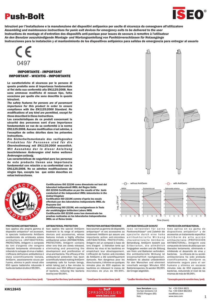
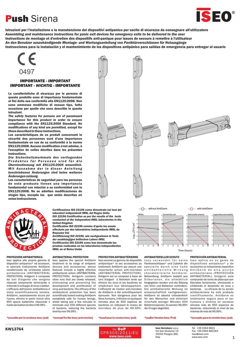
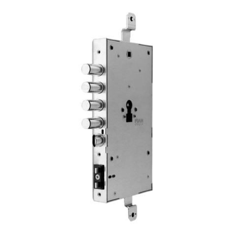
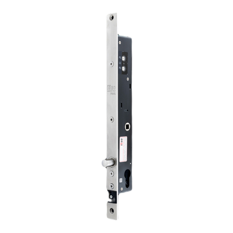
  9. Iseo Zero1 Stylos Smart All Weather User manual

Iseo Zero1 Stylos Smart All Weather User manual

®
iseo.com
ARGO
}
J2.
1J2.
2J2.
3J2.
4
JP
6
JPS
S1
JP
4JP
2JP
0JP
6JP
4JP
2JP
0
J2.
1J2.
2J2.
3J2.
4
JPS
S1
JP
4
JP
2
JP
0
JP
6
JP
4
JP
2
JP
0
JP
6
}
J2.
1J2.
2J2.
3J2.
4
JP
6
JPS
S1
JP
4JP
2JP
0JP
6JP
4JP
2JP
0
J2.
1J2.
2J2.
3J2.
4
JPS
S1
2
1
https://www.iseo.com/it/it/download
3V
CR2032
Lithium
INSTALLATION GUIDE All Weather
GUÍA DE INSTALACIÓN All Weather
Stylos Smart All Weather
Documento no contractual. Sujeto a cambios. Cod. 60000STY2CA00.4 - 19/06/2019
Stylos Smart All Weather inst. guide (EN/ES) - © 2019 Iseo Serrature S.p.a. - www.iseo.com
ELECTRONIC SUPPORT SERVICE
iseozero1.com
Iseo Serrature s.p.a
Via San Girolamo 13
25055 Pisogne (BS)
ITALY
Tel. +39 0364 8821
[email protected]
Download
Iseo Argo App
app.iseo.com
See the
Tutorial Video
WARNINGS
Read this manual prior to use the device in order to ensure a safe and proper use.
Preserve this manual as future reference.
The installation and maintanance of the device must be carried out by qualified technical staff, adequately trained by ISEO.
The instructions should be carefully followed during installation. These instructions and any maintenance
instructions should be passed on by the installer to the user.
No modifications of any kind are permitted, except for those described in these instructions.
The product must be destined only for the use for which it is expressly designed and therefore as a
credential reader for civil and industrial locations. Any other use is considered improper and dangerous.
The electrical connection must be made according to the constructor's instructions and respecting the regulations in force.
Disconnect the power supply before carrying out any technical service that involves opening or accessing
the internal parts of the product.
In the event of a failure and/or poor operation, remove the power supply using the main switch and do not
tamper with it. For all repairs, exclusively contact a technical assistance center authorized by the constructor.
The Bluetooth module is located inside the Control unit, which is max. 5mt far from the Credential reader
(as per supplied cable). Before installing the system, it is therefore necessary to check the Bluetooth
signal coverage. To do that check nearby the Credential reader, the possibility to activate the Control unit
and consequently the Actuator (lock opening), by the smartphone and the Argo app. Attention: Bluetooth
trasmission distance may vary depending on Control unit location and surrounding environment. For example
walls, doors, glazed surfaces can reduce or stop the communication between phone and Control unit.
https://www.iseo.com/it/it/download
Leer el manual de usuario antes de la utilización del producto con el fin de garantizar un uso seguro y adecuado.
Conservar este manual para futuras referencias.
La instalación del producto requiere de personal cualificado, adecuadamente formado por ISEO.
Las instrucciones se deben seguir cuidadosamente durante la instalación. El instalador debe facilitar al
usuario estas instrucciones y cualquier indicación para el mantenimiento.
El producto debe ser destinado únicamente para el uso para el cual fue expresamente diseñado, es decir, como lector
de credenciales para ubicaciones residenciales e industriales. Cualquier otro uso se considera inadecuado y peligroso.
Las conexiones eléctricas deben ser efectuadas según las instrucciones del fabricante y de acuerdo con la normati-
va vigente.
En caso de avería y/o mal funcionamiento, desconecte de la alimentación utilizando el interruptor general y no lo manipule.
Para la reparación, póngase en contacto exclusivamente con un centro de asistencia técnica autorizado por el fabricante.
Antes de realizar cualquier operación de limpieza en el producto, desconecte el dispositivo de la red eléctrica,
apagando el interruptor del sistema.
No se permiten modificaciones de ningún tipo, con la excepción de aquellas descritas en estas instrucciones.
1. VERSIONS AND DIMENSIONS - VERSIONES Y DIMENSIONES
Credential reader
(outdoor module)
Lector de credenciales
(módulo externo)
Control unit
(indoor module)
Unidad de control
(módulo interno)
Spacer for wall
installation
Distanciador para
instalación en la pared
A = 47,5mm
B = 17,5mm
C = 130mm
A = 45mm
B = 19,3mm
C = 113mm
A = 40mm
B = 10mm
C = 125mm
C
A
B
PUSH
PRESIONAR PUSH
PRESIONAR
PULL UP
LEVANTAR PULL UP
LEVANTAR
Side view
Vista lateral
Back view
Vista posterior
2. DISASSEMBLING INDOOR MODULE
2. DESMONTAJE DEL MÓDULO INTERIOR
LEGEND:
S1 = Programming button
JP 0/2/4/6 = Bus Address Jumpers
ADDRESS 0 =
ADDRESS 2 =
ADDRESS 4 =
ADDRESS 6 =
BUS
ADDRESS
(Master)
(slave)
(slave)
(slave)
FUNCTION
3. ELECTRICAL CONNECTIONS
Do not extend the cable supplied
with the external device (5 mt).
Install the internal module only in
a protected area.
0.20÷1.5
Minimum/maximum cross-section
of the cables is:
(24÷15AWG).
Power supply: 8÷30 VDC 0.5A MAX
NEGATIVE (-) GND
POSITIVE (+) Power Supply
LOCKBUS
ADDRESS
BUS
mm²
(Communication Channel)
Control Unit
Circuit View
GREEN + GREY + SHIELD (or black)
RED
WHITE
BROWN
YELLOW
PINK
BLUE
VERDE + GRIS + PANTALLA (o negro)
ROJO
BLANCO
MARRÓN
AMARILLO
ROSA
AZUL
3. CONEXIONES ELÉCTRICAS
NEGATIVO (-) GND
Unidad de control
Vista de circuito
LEYENDA:
DIRECCIÓN 0 =
DIRECCIÓN 2 =
DIRECCIÓN 4 =
DIRECCIÓN 6 =
BUS
DIRECCIONES
(Master)
(slave)
(slave)
(slave)
S1 = Pulsador de programación
JP 0/2/4/6 = Jumper bus dirección
BUS
DIRECCIÓN
Alimentación: 8÷30 VDC 0,5A MAX
La sección mínima/máxima de los cables de
conexión es: 0,20÷1,5 mm2(24÷15 AWG).
No prolongue el cable suministrado con el
lector externo (5 m.).
Instale el dispositivo interno sólo en un área
protegida.
POSITIVO (+) Alimentación
LOCKBUS (Canal de Comunicación)
FUNCIÓN
ADVERTENCIAS
El módulo Bluetooth está dentro de la unidad de control, que está a una distancia máx. de 5 m del lector de credencia-
les (longitud del cable suministrado). Por tanto, es necesario comprobar la cobertura de la señal Bluetooth antes de
realizar la instalación del sistema. Para ello, compruebe que, en el lector de credenciales, sea posible activar la unidad
de control y por consiguiente el actuador (apertura de cerradura), mediante el smartphone y la aplicación Argo.
Atención: la distancia de la transmisión Bluetooth puede variar en función de la ubicación de la unidad de control y
del entorno. Por ejemplo, las paredes, las puertas y las cristaleras pueden reducir o interrumpir la comunicación entre
el teléfono y la unidad de control.
TECHNICAL DATA - DATOS TÉCNICOS
Power Supply
:
8÷30 VDC 0.5A MAX
Operating temperature: -20°C + 60°C
RFID: frequecy 13,553 - 13,567 MHz, maximum magnetic field: 0,89 µA/m (measured at 10m at the
maximum power capacity).
Radio: frequency 2,40 - 2,4835 GHz, maximum power: 5,25 mW
EN
Alimentación: 8÷30 VCC 0,5 A MÁX.
Temperatura de uso: -20 °C + 60 °C
RFID: frecuencia 13,553 - 13,567 MHz, campo magnético máximo: 0,89 µA/m (medido a 10 m a la
máxima potencia suministrable).
Radio: frecuencia 2,40 - 2,4835 GHz, potencia máxima: 5,25 mW
ES
Lithium Battery - Pila de litio
CR2032 - 3 V
ES
EN Risk of explosion if the battery is replaced with an incorrect type.
Dispose of batteries according to your local environmental laws and guidelines.
Battery replacement must be carried out by qualified technical staff.
For the replacement battery procedure, read the user manual available at app.iseo.com.
Peligro de explosión si la pila se sustituye por otra de tipo incorrecto.
Elimine por separado las pilas usadas siguiendo las disposiciones locales.
La sustitución de la pila debe ser efectuada por personal técnico cualificado.
Para el procedimiento de sustitución de la pila, consulte el manual del usuario disponible en el sitio web app.iseo.com.
Power supply
8
÷
24VDC 25W
COM
NO/NC
GND
IN AN
I/O 2
I/O 1
VCC
GND
L2L1P1 P2 LRL
J P 3
LPW
J P 2L C HJ P 1LV O
V2 Output
V1 Output
OPEN
V PWR +
GND
EARTH
1
2
Power supply
8
÷
24VDC 25W
COM
NO/NC
GND
IN AN
I/O 2
I/O 1
VCC
GND
L2L1P1 P2 LRL
J P 3
LPW
J P 2L C HJ P 1
LV O
V2 Output
V1 Output
OPEN
V PWR +
GND
EARTH
1
2
83
JP
6JP
4JP
2JP
0
J2.
1J2.
2J2.
3J2.
4
JPS
S1
JP
6JP
4JP
2JP
0
J2.
1J2.
2J2.
3J2.
4
JPS
S1
Power supply
8
÷
24VDC 25W
COM
NO/NC
GND
IN AN
I/O 2
I/O 1
VCC
GND
L2L1P1 P2 LRL
J P 3
LPW
J P 2L C HJ P 1L V O
V2 Output
V1 Output
OPEN
V PWR +
GND
EARTH
1
2
Ø 3.2 mm
(max/máx)
Ø 3.2 mm
(max/máx)
83
26
4.1 EXCHANGE OF CODED KEYS WITH ACTUATOR: LOCKBUS TYPE SELECTION
4.1 INTERCAMBIO DE LA CLAVE CIFRADA CON EL ACTUADOR: SELECCIÓN TIPO LOCKBUS
1
Switch on the Actuator and check if red led flashes
2 times (lockbus 2).
If it flashes 1 time follow point 2 to change the
lockbus type.
Encienda el Actuador y verifique si el led rojo
parpadea 2 veces (lockbus 2).
Si parpadea 1 vez continúe al punto 2 para cambiar
el tipo de lockbus.
2
Switch on the Actuator keeping pressed both buttons
simultaneously for 1 sec.
Switch on it again to check if now red led flashes 2 times.
If not repeat the procedure.
Encienda el Actuador, manteniendo presionados ambos
botones simultáneamente durante 1 s.
Encienda nuevamente para verificar si el led rojo parpadea
2 veces.
En caso contrario, repita el procedimiento.
Red led
flashing
Parpadeo
led rojo
4.2 EXCHANGE OF CODED KEYS WITH ACTUATOR: JUMPER SETTING
4.2 INTERCAMBIO DE LA CLAVE CIFRADA CON EL ACTUADOR: AJUSTE DEL JUMPER
Set jumpers on Actuator and Stylos Control Unit as per pictures below. Note this configuration is correct
only in case of 1 Stylos (Master) and 1 Actuator (Slave).
Ajuste los jumpers en el Actuador y en la Unidad de Control del Stylos como se muestra en la siguiente imagen.
Tenga en cuenta que esta configuración es correcta sólo en el caso de 1 Stylos (Master) y 1 Actuador (Slave).
EN: for more information
about jumper setting with
different configuration, refer
to the user manual.
ES: para obtener más
información sobre el ajuste
de los jumpers con diferen-
tes configuraciones, consul-
lte el manual de usuario.
Stylos Master
address 0
Actuator
address 1
Actuador
dirección 1
Stylos Master
dirección 0
Control Unit
Circuit View
4.3 EXCHANGE OF CODED KEYS WITH ACTUATOR: EXCHANGE KEYS
4.3 INTERCAMBIO DE LA CLAVE CIFRADA CON EL ACTUADOR: INTERCAMBIO DE CLAVE
Switch on the actuator
keeping pressed one
button for 3 sec.
Encienda el actuador
manteniendo presionado
un botón durante 3 s.
Actuator
address 1
Actuador
dirección 1
Switch on the Stylos Control Unit
keeping pressed the button and
wait for the light signal, then
release it immediately.
Conecte la Unidad de Control del
Stylos manteniendo presionado el
pulsador y espere la señal
acústica, depués suelte el botón
rojo inmediatamente.
Stylos Master
address 0
Stylos Master
dirección 0
Control Unit
Circuit View
EN: for more information regarding the exchange of keys, see the Tutorial Video available at app.iseo.com.
ES: para obtener mas información sobre el cambio de la clave, consulte manual de usuario.
Enlace VideoTutorial app.iseo.com.
6.1 INSTALLATION ON A METAL PROFILE
6.1 INSTALACIÓN SOBRE UN PERFIL METÁLICO
Ø 26 mm
3.9 x 19 mm Ø 5 mm
Ø 5 mm
3.9 x 30 mm
6.2 INSTALLATION WITH A SPACER ON A WALL
6.2 INSTALACIÓN CON EL DISTANCIADOR SOBRE UNA PARED
5 x 25 mm
6.3 INSTALLATION WITHOUT THE SPACER
6.3 INSTALACIÓN SIN DISTANCIADOR
Take care not to damage
the cables while installing
the device.
Tenga cuidado de no dañar
los cables durante la
instalación.
Check the connections on
section 3 before powering
up the device.
Verifique las conexiones
de la sección 3 antes de
alimentar el dispositivo.
Tenga cuidado de no dañar
los cables durante la
instalación.
Verifique las conexiones
de la sección 3 antes de
alimentar el dispositivo.
6.4 INSTALLATION WITH THE SPACER
6.4 INSTALACIÓN CON DISTANCIADOR
Take care not to damage
the cables while installing
the device.
Check the connections on
section 3 before powering
up the device.
5. BLUETOOTH SIGNAL COVERAGE
5. COBERTURA DE LA SEÑAL BLUETOOTH
Control unit
Unidad de control
Credential reader
Lector de credenciales
Actuator
Actuador
Electric lock
Cerradura eléctrica
On average - de media
10mt*
Max/Máx 5mt
Provided cable length
Longitud del cable
suministrado
= 5mt
*EN: Bluetooth trasmission distance may vary depending on Control unit location and surrounding
environment. For example walls, doors, glazed surfaces can reduce or stop the communication between
phone and Control unit.
*ES:la distancia de la transmisión Bluetooth puede variar en función de la ubicación de la unidad de
control y del entorno. Por ejemplo, las paredes, las puertas y las cristaleras pueden reducir o interrum-
pir la comunicación entre el teléfono y la unidad de control.

Other Iseo Door Lock manuals

Iseo Zero1 Aries User manual

Iseo

Iseo Zero1 Aries User manual

Iseo Push Sirena User manual

Iseo

Iseo Push Sirena User manual

Iseo 214E Series User manual

Iseo

Iseo 214E Series User manual

Iseo Multiblindo Easy EXIT Installation guide

Iseo

Iseo Multiblindo Easy EXIT Installation guide

Iseo PERFORMA Elettrica Installation guide

Iseo

Iseo PERFORMA Elettrica Installation guide

Iseo X1R Smart User manual

Iseo

Iseo X1R Smart User manual

Iseo Push-Bolt User manual

Iseo

Iseo Push-Bolt User manual

Iseo MULTIBLINDO eMOTION EXIT Installation guide

Iseo

Iseo MULTIBLINDO eMOTION EXIT Installation guide

Iseo Thesis 2.0 Standard User manual

Iseo

Iseo Thesis 2.0 Standard User manual

Iseo MA1A User manual

Iseo

Iseo MA1A User manual

Iseo ARIES User manual

Iseo

Iseo ARIES User manual

Iseo x1R Easy User manual

Iseo

Iseo x1R Easy User manual

Iseo Zero1 Thesis 2.0 Standard User manual

Iseo

Iseo Zero1 Thesis 2.0 Standard User manual

Iseo Electa Perfecta 990850 Installation guide

Iseo

Iseo Electa Perfecta 990850 Installation guide

Iseo X1R Smart User manual

Iseo

Iseo X1R Smart User manual

Iseo Zero1 Aries Smart User manual

Iseo

Iseo Zero1 Aries Smart User manual

Iseo Pad-Bolt User manual

Iseo

Iseo Pad-Bolt User manual

Iseo Electa User manual

Iseo

Iseo Electa User manual

Iseo ARIES User manual

Iseo

Iseo ARIES User manual

Iseo PERFORMA 040950 Installation guide

Iseo

Iseo PERFORMA 040950 Installation guide

Iseo Trim Installation guide

Iseo

Iseo Trim Installation guide

Iseo 214910654 D Series User manual

Iseo

Iseo 214910654 D Series User manual

Iseo CSF Series User manual

Iseo

Iseo CSF Series User manual

Iseo Aries PremiApri Meroni User manual

Iseo

Iseo Aries PremiApri Meroni User manual

Popular Door Lock manuals by other brands

HYF BH201 manual

HYF

HYF BH201 manual

SECO-LARM SD-996C-NUQ manual

SECO-LARM

SECO-LARM SD-996C-NUQ manual

Samsung SHP-DP608 user manual

Samsung

Samsung SHP-DP608 user manual

Assa Abloy Corbin Russwin ED2400 Series installation instructions

Assa Abloy

Assa Abloy Corbin Russwin ED2400 Series installation instructions

ZKTeco TL400B Installation instruction

ZKTeco

ZKTeco TL400B Installation instruction

Extel WECA 90301.4 manual

Extel

Extel WECA 90301.4 manual

Kaba E-Flash 680 user guide

Kaba

Kaba E-Flash 680 user guide

Assa Abloy Lockwood 8653 installation instructions

Assa Abloy

Assa Abloy Lockwood 8653 installation instructions

Schlage Schlage LiNK brochure

Schlage

Schlage Schlage LiNK brochure

Allegion 1413.KE Operation

Allegion

Allegion 1413.KE Operation

Soss UltraLatch instructions

Soss

Soss UltraLatch instructions

Kaba ILCO Generation E-760 Series installation guide

Kaba

Kaba ILCO Generation E-760 Series installation guide

Best IDH Max 1300 installation instructions

Best

Best IDH Max 1300 installation instructions

Assa Abloy Corbin Russwin MP9800 Series installation instructions

Assa Abloy

Assa Abloy Corbin Russwin MP9800 Series installation instructions

Salto Neo N E1 Series installation guide

Salto

Salto Neo N E1 Series installation guide

Directed XpressKit DBALL installation guide

Directed

Directed XpressKit DBALL installation guide

ZKTeco LH3600 Installation instruction

ZKTeco

ZKTeco LH3600 Installation instruction

CAMDEN CX-ED1259-L installation instructions

CAMDEN

CAMDEN CX-ED1259-L installation instructions

manuals.online logo
manuals.online logoBrands
  • About & Mission
  • Contact us
  • Privacy Policy
  • Terms and Conditions

Copyright 2025 Manuals.Online. All Rights Reserved.